Note: Determine the left and right sides of the machine from the normal operating position.
This kit fits 2-Post ROPS Extension Kit Model 03611 only.
Setup
Preparing the Machine
-
Park the machine on a level surface, engage the parking brake, lower the cutting units, shut off the engine, and remove the key from the ignition switch.
-
If your machine has lights on the ROPS posts, remove the lights and mounting hardware from the ROPS posts.
Note: Retain the lights and mounting hardware.
-
If your machine has a 2 post ROPS extension, remove the side panels that are used to mount the ROPS post lights.
Note: Retain the corresponding hardware.
-
Position the seat assembly to the furthest forward position.
Assembling the Cage
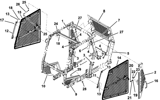
Parts needed for this procedure:
| Left side panel | 1 |
| Right side panel | 1 |
| Lower support (shorter) | 2 |
| Upper support (longer) | 4 |
| Channel mount | 2 |
| Left rear panel | 1 |
| Right rear panel | 1 |
| Lower rear panel | 1 |
| Top rear screen | 1 |
| Lower left panel | 1 |
| Lower right panel | 1 |
| Carriage bolt (1/4 x 3/4 inch) | 4 |
| Flange nut (1/4 inch) | 4 |
| Left door-mount assembly | 1 |
| Right door-mount assembly | 1 |
| Spacer | 12 |
| Left door assembly | 1 |
| Right door assembly | 1 |
| Grab handle | 1 |
| Button-head screw (5/16 x 3/4 inch) | 84 |
| Flange nut (5/16) | 103 |
| Mount bracket | 2 |
| Carriage screw (3/8 x 7/8 inch) | 2 |
| Flange nut (3/8) | 2 |
Refer to Figure 8 as you perform the following steps.
Note: Ensure that all parts are assembled loose. Complete the assembly of the kit; then, tighten all the fasteners.
-
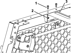
Use button-head screws (5/16 x 3/4 inch) and flange nuts (5/16 inch) to install the left side panel and the right side panel (Figure 1).
Note: Install the panels with the carriage screws inserted into the bottom of the panel mounting holes.
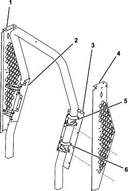
-
Use button-head screws (5/16 x 3/4 inch) and flange nuts (5/16 inch) to install the 2 upper supports and the 2 lower supports along with the left rear panel and the right rear panel (Figure 1).
Note: Install the carriage screws so that the nuts will not be accessible from outside of the cage.
-
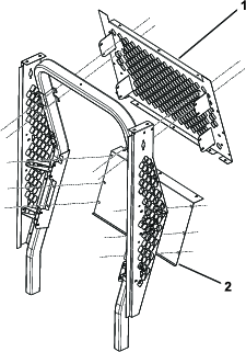
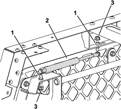
Use button-head screws (5/16 x 3/4 inch) and flange nuts (5/16 inch) to install the lower rear panel (Figure 2).
-
Use button-head screws (5/16 x 3/4 inch) and flange nuts (5/16 inch) to install the top rear screen (Figure 2).
Note: Tilt the top rear screen up beneath the rear roof mount of the 2-post ROPS extension kit.
-
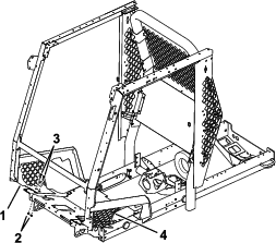
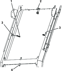
Use carriage screws (3/8 x 7/8 inch) and flange nuts (3/8 inch) and the bolts supplied with the traction unit and the 2 post ROPS extension kit to install the lower left panel and the lower right panel (Figure 3).
-
Use 2 carriage screws (1/4 x 3/4 inch) and 2 flange nuts (1/4 inch) on each side to secure the bottom of the lower left panel and the lower right panels (Figure 3).
-
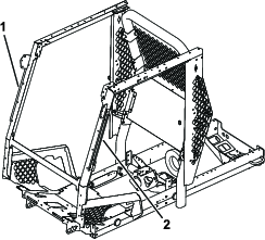
Use button-head screws (5/16 x 3/4 inch) and flange nuts (5/16 inch) to install the left door-mount assembly and the right door-mount assembly (Figure 4 and Figure 6).
-
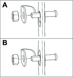
Install 2 spacers on each door-mount assembly (1 on the upper hinge pin and 1 on the lower hinge pin); refer to Figure 5.
Note: If the door pin latch is out of alignment, it may be necessary to add or remove washers until the door is aligned.
-
Install each door by sliding the hinges onto the hinge pins (Figure 6).
-
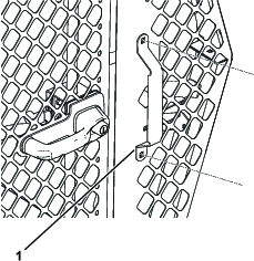
Use button-head screws (5/16 x 3/4 inch) and flange nuts (5/16 inch) to install the grab handle on the left side panel (Figure 7).
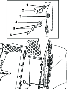
Assembling the Latch Pins
Parts needed for this procedure:
| Jam nut | 2 |
| Pin guard | 2 |
| Cam | 2 |
| Thrust washer | 4 |
| Latch pin | 2 |
-
Ensure that you adjusted the control console to the furthest inward position.
-
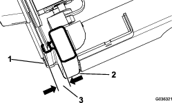
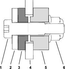
Align the latch-pin cam with the opening at the striker plate in the position shown in Figure 9.
-
Insert the latch pin (without the washers at first) into the latch-pin cam (Figure 9).
Note: If the latch pin is not centered in the door latch, add 1 or 2 of the thrust washers.
-
Align the latch pin and the jam nut onto the back side of the opening at the striker plate (Figure 9).
-
Tighten the jam nut onto the latch pin by hand (Figure 9).
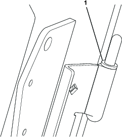
Adjusting the Latch Pins
-
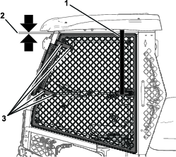
Center the latch pin in the latch-pin mount bracket on the rail (Figure 10).
-
Close the door completely and view where the latch pin comes into contact with the door latch.
Note: If the latch pin does not completely engage with the door latch, add 1 or 2 thrust washers between the latch-pin cam and the latch pin.
-
Close the door completely and measure the height of the bubble seal to the sealing surface of the cab rail, and ensure that the measurement is 1.9 to 2.2 cm (3/4 to 7/8 inch) as shown in Figure 11.
Note: If the height measured is more than the zone specification, rotate the latch-pin cam 45° toward the inside of the cab to achieve the specified measurement. If the height measured is less than the zone specification, perform the opposite of the above procedure.
Note: The latch pin self centers.
-
Tighten the jam nut once the latch pin reaches 1.9 to 2.2 cm (3/4 to 7/8 inch) as shown in Figure 11.
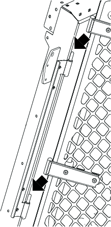
Adjusting the Doors
-
Loosen the door-latch pin just enough to allow it to slide up and down.
-
Position 1 end of a ratchet strap on the top frame rail and the other end on the door handle (Figure 12).
-
Shut the door.
-
Loosen the 4 bolts and the 4 nuts on the door hinge (Figure 12).
-
Tighten the ratchet strap to pull the door up.
Ensure that the gap measurement between the door and the frame is 1.3 cm (1/2 inch).
-
Tighten the bolts and nuts on the door hinge and the door-latch pin.
-
Remove the ratchet strap.
-
Repeat the procedure for the other door.
Note: Adjusting the door may cause the latch to lose alignment. To correct, add thrust washers as necessary; refer to Assembling the Latch Pins.
Installing the Gas Springs
Parts needed for this procedure:
| Support mount | 1 |
| Ball stud | 4 |
| Gas spring | 2 |
| Button-head screw (5/16 x 3/4 inch) | 4 |
| Flange nut (5/16 inch) | 12 |
-
Install each side of the support mount with 2 button-head screws (5/16 x 3/4 inch) and 2 flange nuts (5/16 inch); refer to Figure 13.
-
Use 2 ball studs and 2 flange nuts (5/16 inch) on each side to secure the springs to the door cage assemblies and the forward-most holes of the support mount (Figure 14).
Note: Install the springs with the cylinder end (wide) on the door and the piston end (narrow) on the spring mount.
Installing the Windshield
Parts needed for this procedure:
| Dual-tab mount | 1 |
| Side tab mount | 2 |
| Top tab mount | 1 |
| Rivet | 6 |
| Lower windshield assembly | 1 |
| Upper windshield assembly | 1 |
| Shoulder bolt (5/16 x 1-1/2 inches) | 13 |
| Backup washer | 13 |
| Rubber bushing (0.31 inch long) | 13 |
| Rubber bushing (0.56 inch long) | 13 |
| Flange nut (5/16 inch) | 13 |
Note: Refer to Figure 15 and Figure 16 as you perform the following steps.
-
Install the dual-tab mount between the upper and lower windshield frame on the ROPS.
-
Install the 2 side tab mounts into the holes provided in the 2 Post ROPS Extension pillar cover.
-
Install the top tab mount into the hole provided in the 2 Post ROPS Extension front panel.
-
Install the lower and upper windshield assemblies with 13 bolts (5/16 x 1-1/2 inches), 13 backup washers, 13 rubber bushings (0.31 inch long), 13 rubber bushings (0.56 inch long), and 13 flange nuts (5/16 inch).
Completing the Installation
-
Ensure that all fasteners are tightened.
-
Install any attachments that you previously removed, such as lights, onto the left and right panels.