Introduction
The light adapter kit is used with the optional North American road light kit or the optional EU light kit on Groundsmaster 4000 or 4100 series rotary mowers with a cab.
Warning
CALIFORNIA
Proposition 65 Warning
Use of this product may cause exposure to chemicals known to the State of California to cause cancer, birth defects, or other reproductive harm.
Setup
Preparing the Machine
-
Move the machine to level ground and engage the parking brake.
-
Lower the cutting units to the ground.
-
Shut off the engine and remove the key.
-
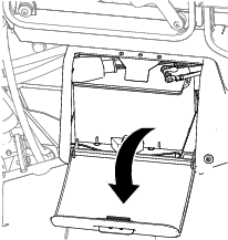
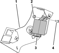
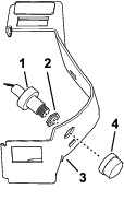
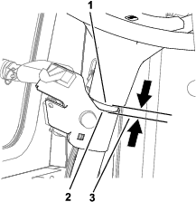
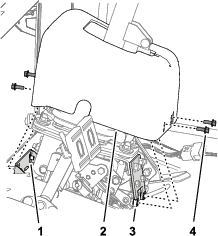
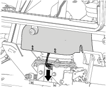
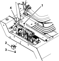
Open the battery compartment door (Figure 1).
-
Disconnect the negative (-) battery cable from the battery.
Warning
Incorrect battery cable routing could damage the machine, cables, and causing sparks. Electrical sparks can cause the battery gasses to explode, resulting in personal injury.
-
Always disconnect the negative (black) battery cable before disconnecting the positive (red) cable.
-
Always connect the positive (red) battery cable before connecting the negative (black) cable.
Warning
Battery terminals or metal tools could short against metal machine components, causing sparks. Electrical sparks can cause the battery gasses to explode, resulting in personal injury.
-
When removing or installing the battery, do not allow the battery terminals to touch any metal parts of the machine.
-
Do not allow metal tools to short between the battery terminals and metal parts of the machine.
-
Always keep the battery strap in place to protect and secure the battery.
-
Preparing the Column Bracket
Parts needed for this procedure:
| Column bracket | 1 |
| Plug (rectangular) | 1 |
| Clip nut | 2 |
| Plug (round) | 1 |
| Flange locknut (#10-24) | 1 |
| Screw (#10-24 x 1/2 inch) | 2 |
| Paddle switch | 1 |
-
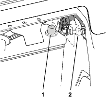
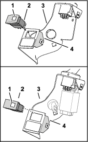
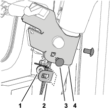
Install the rectangular plug into the column bracket as shown in Figure 3.
-
Assemble the 2 clip nuts onto the short flanges to the column bracket (Figure 3).
-
Perform one of the following steps:
-
If your machine has the optional North American road light kit, install the round plug (Figure 4).
-
If your machine has the optional EU light kit or horn kit, assemble the horn switch from the kit as follows:
-
-
If your machine has the optional EU light kit, assemble the flasher module (part of the optional EU light kit or optional horn kit) onto the column bracket (Figure 6) with the screw (#10-24 x 1/2 inch) and flange locknut (#10-24), and tighten the screw and locknut to 419 to 513 N∙cm (37 to 47 in-lb).
-
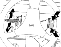
Assemble the paddle switch into the column bracket with the handle of the switch aligned down (Figure 7).
Note: Align the arrow graphics on the handle of the paddle switch as shown in Figure 8.
Ensure that the switch snaps securely into the bracket.
-
Assemble the rocker switch into the column bracket with the light of the switch aligned toward the short flange of the bracket (Figure 9).
Ensure that the switch snaps securely into the bracket.
Connecting the Wire Harness to the Column Bracket Assembly
Parts needed for this procedure:
| Wire harness | 1 |
-
If your machine has the optional North American road light kit and the optional horn kit is not installed, connect the wire harness as follows:
-
If your machine has the optional EU light kit, connect the wire harness as follows:
-
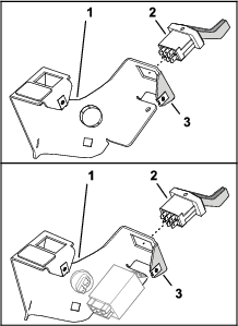
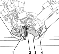
Plug the 8-socket connector labeled HAZARD SWITCH - CE onto the 8-pin connector of the hazard switch (Figure 11).
-
Plug the 8-socket connector labeled TURN SIGNAL -CE onto the 8-pin connector of the paddle switch (Figure 11).
-
Plug the 6-socket connector labeled CE FLASHER MODULE onto the 6-pin connector of the flasher module (Figure 11).
-
Connect the 2 terminals to the horn switch (Figure 11).
-
Installing the Column Bracket and Wire Harness Assembly
Parts needed for this procedure:
| Column-mount bracket | 1 |
| Cable tie | 3 |
| Carriage bolt (3/8 x 3/4 inch) | 2 |
| Flange locknut (3/8 inch) | 2 |
| Cover | 1 |
| Button-head screw (#10 x 1/2 inch) | 2 |
Installing the Column Bracket to the Steering Column
-
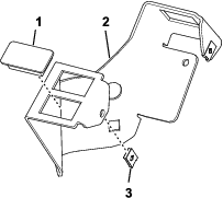
Assemble the cable tie onto the cable-mount bracket as shown in Figure 12.
-
Align the column-bracket assembly to the steering column as shown in Figure 13.
Position the column-bracket assembly so that there is a gap 13 mm (1/2 inch) between the edge of bracket and the bottom edge of the steering wheel.
-
Align the column-mount bracket between the kit wire harness and the steering column (Figure 14).
-
Loosely assemble the column-mount bracket and the column bracket to the steering column (Figure 14) with the 2 carriage bolts (3/8 x 3/4 inch) and 2 flange locknut (3/8 inch).
-
Secure the kit wire harness to the column-mount bracket with the cable tie (Figure 15) that you assembled in step 1.
-
Torque the 2 flange lock nuts to 37 to 45 N∙m (27 to 33 ft-lb).
-
Assemble the cover to the column-bracket assembly (Figure 16) with 2 button-head screw (#10 x 1/2 inch), and tighten the screws by hand.
Making a Notch in the Steering Cover
-
Remove the 4 flange-head bolts (1/4 x 3/4 inch) that secure the steering cover to the cover mount and the column support (Figure 17).
-
Locate the mid-point in the opening of the cover and mark that locations with a pencil (Figure 18).
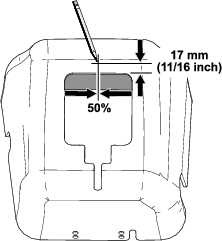
-
Measure 17 mm (11/16 inch from the edge and mark the cover as shown in Figure 18.
-
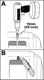
Drill a 16 mm (5/8 inch) hole at the intersection of the marks that you made in steps 2 and 3 (Figure 20).
-
Cut the cover to extend the hole to the opening in the cover as shown in (Figure 20).
Routing and Connecting the Kit Wire Harness
-
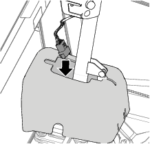
Route the kit wire harness through the cover as shown in Figure 20.
-
Route the kit wire harness in front of the steering valve and down as shown in Figure 21
-
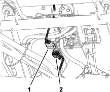
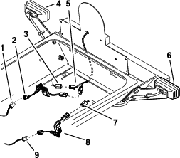
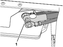
Connect the 12-pin connector of the (kit wire harness into the 12-socket connector of the machine wire harness (Figure 22).
-
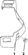
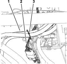
Secure the kit wire harness to the steering valve hoses with a cable tie (Figure 23).
-
Assemble the steering cover over the steering valve, cover mount, and the column support with the 4 flange-head bolts (1/4 x 3/4 inch) that you removed in step 1 of ; refer to Figure 17.
-
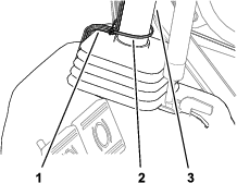
Secure the kit wire harness to the steering column with a cable tie as shown in Figure 24.
Installing the Relay and Wire Harness
Parts needed for this procedure:
| Screw (#10 x 7/8 inch) | 2 |
| Nut (#10) | 2 |
| Relay | 1 |
| Right wire harness (Blue wire) | 1 |
| Left wire harness (Brown wire) | 1 |
-
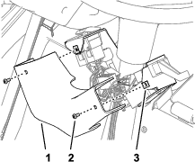
Remove the cover from the right side of the seat.
-
Install the relay with 2 screws (#10 x 7/8 inch) and nuts (#10) as shown in Figure 25.
-
Locate the existing connector located to the lower right of the seat and connect it to the relay.
-
Replace the wire harnesses for the tail lights that came with the light kit with the harnesses in this kit.
-
Install the harness with the blue wire on the right side as shown in Figure 26.
-
Install the harness with the brown wire on the left side as shown in Figure 26.
Finishing the Installation
-
Assemble the terminal of the negative battery cable to the negative post of the battery, and tighten the nut of the terminal by hand (Figure 27).
-
Close the battery compartment door securely.
-
Test all the functions of the kit.
-
Verify the function of the left and right brakes and the parking brake.
-
Check the safety interlock system for the brakes. Refer to the Operator’s Manual for the machine.
Operation
Using the Turn Signal and Hazard Signal
Using the Hazard Signal
Using the Turn Signal
-
Set the hazard signal to the ON position; refer to Using the Hazard Signal.
-
Use the turn-signal paddle to signal your turn as follows:
Using the Horn
Press the horn button to activate the horn.