Introduction
The GeoLink ™ spray system kit is an attachment for a turf spray application vehicle and is intended to be used by professional, hired operators in commercial applications. It is designed primarily for spraying on well-maintained lawns in parks, golf courses, sports fields, and on commercial grounds.
Visit www.Toro.com for more product safety information, including safety tips, training materials, accessory information, help finding a dealer, or to register your product.
Using this product for purposes other than its intended use could prove dangerous to you and bystanders.
Note: Read this information carefully to learn how to operate and maintain your product properly and to avoid injury and product damage. You are responsible for operating the product properly and safely.
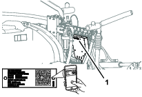
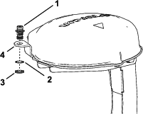
Whenever you need service, genuine Toro parts, or additional information, contact an Authorized Service Dealer or Toro Customer Service and have the model and serial numbers of your product ready. Figure 1 identifies the location of the model and serial numbers on the product. Write the numbers in the space provided.
Important: With your mobile device, you can scan the QR code (if equipped) on the serial number plate to access warranty, parts, and other product information.
This manual identifies potential hazards and has safety messages identified by the safety-alert symbol (Figure 2), which signals a hazard that may cause serious injury or death if you do not follow the recommended precautions.

This manual uses 2 words to highlight information. Important calls attention to special mechanical information and Note emphasizes general information worthy of special attention.
Safety
Warning
Chemical substances used in the spray system may be hazardous and toxic to you, bystanders, animals, plants, soils, or other property.
-
Carefully read and follow the chemical warning labels and safety data sheet (SDS) for all chemicals used and protect yourself according to the chemical manufacturer's recommendations. For example, use appropriate personal protective equipment (PPE), including face and eye protection, gloves, or other equipment to guard against personal contact with a chemical.
-
There may be more than 1 chemical used and information on each chemical; assess each chemical.
-
Refuse to operate or work on the sprayer if this information is not available.
-
Before working on a spray system, ensure that the system has been triple rinsed and neutralized according to the recommendations of the chemical manufacturer(s) and that all the valves are cycled 3 times.
-
Verify that there is an adequate supply of clean water and soap nearby, and immediately wash off any chemicals that contact you.
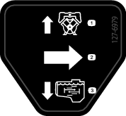
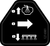
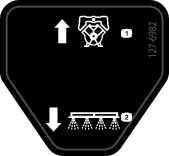
Safety and Instructional Decals
|
Safety decals and instructions are easily visible to the operator and are located near any area of potential danger. Replace any decal that is damaged or missing. |
Setup
Preparing to Install the Kit
Preparing the Sprayer Tank and Optional Rinse Tank
-
Clean the sprayer; refer to Cleaning the Sprayer in the Operator’s Manual for the machine.
Important: Completely empty the sprayer tank before installing the GeoLink Spray System Finishing Kit.
-
For machines with the optional tank-rinse kit, perform the following:
-
Pump the water from the rinse tank into the sprayer tank; refer to Operating the Rinse Kit in the Installation Instructions for the Tank-Rinse Kit.
-
Drain the water from the sprayer tank; refer to Cleaning the Sprayer in the Operator’s Manual for the machine.
-
-
Extend the left- and right-spray sections to the horizontal position.
-
Park the machine on a level surface, engage the parking brake, shut off the engine, and remove the key; refer to the Operator’s Manual.
Important: Park the machine on a level surface before installing the GeoLink kit.
Disconnecting the Battery
-
Rotate the KEY SWITCH to the OFF position, and remove the key; refer to the Operator’s Manual.
-
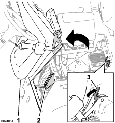
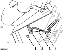
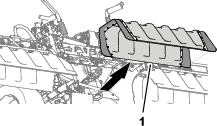
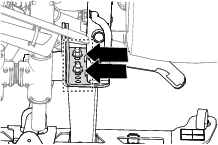
Unlatch the seat by pushing the seat-latch handle rearward (Figure 3).
-
Rotate the seat and seat plate forward until the end of the prop rod, at the prop-rod bracket, is at the bottom of the slot in the bracket (Figure 3).
-
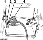
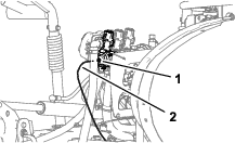
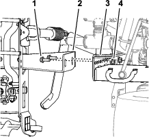
Remove the bolt and nut that secures the terminal of the negative-battery cable to the negative post of the battery.
Warning
Electrical sparks can cause the battery gasses to explode, resulting in personal injury.
Incorrect battery cable routing could damage the sprayer and cables, causing sparks.
-
Always disconnect the negative (black) battery cable before disconnecting the positive (red) cable.
-
Always connect the positive (red) battery cable before connecting the negative (black) cable.
Battery terminals or metal tools could short against metal sprayer components, causing sparks.
-
When removing or installing the battery, do not allow the battery terminals to touch any metal parts of the sprayer.
-
Do not allow metal tools to short between the battery terminals and metal parts of the sprayer.
-
Always keep the battery strap in place to protect and secure the battery.
-
-
Slide back the insulator cover and remove the bolt and nut that secures the terminal of the positive-battery cable to the positive post of the battery. (Figure 4).
Note: Ensure that the terminals of the battery cables do not touch the battery posts.
-
Allow the engine to cool completely.
Removing the Seat and the Engine-Access Panel
Removing the Seat
-
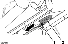
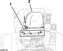
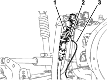
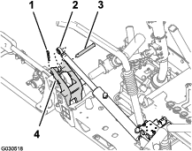
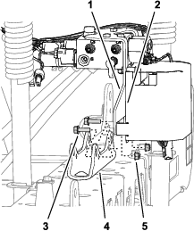
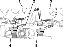
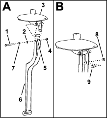
Remove the 2-socket connector of the machine wire harness that connects to the seat-switch connector (Figure 5).
-
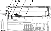
Remove the hairpin that secures the prop rod to the bracket at the bottom of the seat plate (Figure 6).
-
Remove the 2 hairpins that secure the pivot fitting of the seat plate to the chassis brackets (Figure 7).
-
Remove the 2 pivot pins that secure the seat and seat plate to the chassis (Figure 7).
-
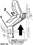
Lift the seat and seat plate up and out of the machine (Figure 8).
Removing the Left and Right Front Fenders and the Hood
Removing the Left and Right Front Fenders
-
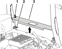
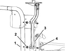
Remove the 2 push-in fastener that secure the left, front fender to the lower ROPS channel (Figure 10).
Note: Discard push-in fasteners that you removed.
-
Remove the 3 bolts (5/16 x 1 inch) and 3 washers (5/16 inch) that secure the fender to the frame of the machine (Figure 11).
-
Remove the fender from the machine.
Note: Discard push-in fasteners that you removed.; retain the fender, bolts, and washers for installation in Installing the Left and Right Front Fenders.
-
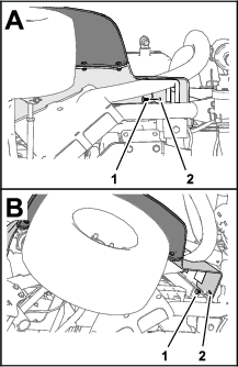
Remove the 6 push-in fasteners and 5 washer (9/16 x 1/2 inch) that secure the inner-fender shroud to the frame of the machine (Figure 12).
-
Remove the inner-fender shroud from the machine (Figure 13).
Note: Discard push-in fasteners that you removed.
-
Repeat steps 1 through 5 for the fender and inner-fender shroud at the other side of the machine.
Removing the Hood
-
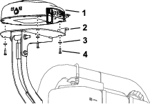
Disconnect the 2 electrical connectors (2-socket) of the machine wire harness from the 2-pin connectors of the left and right headlights (Figure 14).
-
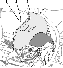
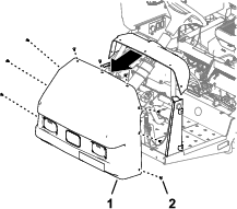
Remove the 9 push-in fasteners that secure the hood to the dash and frame of the machine (Figure 15).
Note: Retain the push-in fasteners for installation in Installing the Hood.
-
Remove the hood from the machine (Figure 15).
Note: Discard push-in fasteners that you removed.
Disconnecting the Optional Foam-Marker Kit
Parts needed for this procedure:
| Tube assembly—Toro Part No. 114-9553 | 2 |
| Cable tie | 8 |
Removing the Liquid and Air Tubes at the Compressor
-
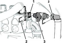
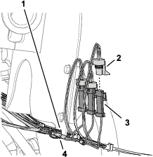
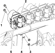
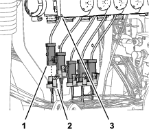
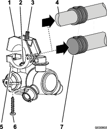
At the connection panel of the compressor for the foam-marker kit, secure a cable tie around the clear and blue tubing for the right-spray section (Figure 16).
-
Press in the locking collar (Figure 17).
-
Pull out the tube from the fitting (Figure 17).
-
Repeat steps 2 and 3 for the other 3 tubes for the spray sections.
Removing the Liquid and Air Tubes at the Compressor
-
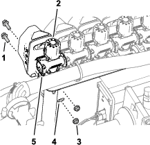
At the connection panel of the compressor for the foam-marker kit, secure a cable tie around the clear and blue tubing for the right-spray section (Figure 18).
-
Loosen the compression nuts for the 2 clear and 2 blue tubes for the foam nozzles at the left- and right-spray section (Figure 18).
-
Remove the 4 tubes from the compression fittings for the spray sections (Figure 18).
Removing the Liquid and Air Tubes to the Spray Sections
-
At the outer-spray section, use a piece of tape to mark the left liquid and air tubes for the left spray section and the right liquid and air tubes for the right spray section.
-
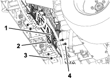
Move the tubes for the foam nozzles at the left- and right-spray section rearward and through the R-clamp near the pivot point for the spray section (Figure 19).
-
If your machine has the center boom-extension kit installed, loosely secure the free end of the liquid and air tubes to the outer-spray section. and skip the procedures for Preparing the New Tube Assemblies for the Foam-Marker Nozzles and Installing the New Tube Assembly.
Preparing the New Tube Assemblies for the Foam-Marker Nozzles
-
Remove the cable ties that secure the liquid and air tubes of the foam marker kit to the outer-spray section (Figure 20).
-
At the foam-marker nozzle, loosen the compression nut that secures the blue tube (water) to the blue compression fitting of the foam-marker nozzle (Figure 21).
-
Loosen the compression nut that secures the clear tube (air) to the white compression fitting of the foam-marker nozzle of the foam-marker nozzle (Figure 21).
-
Remove the liquid and air tubes from the machine.
-
Remove the compression nuts at the ends of the tubes (Figure 21).
Note: Retain the compression nuts for installation in step 1 of Installing the New Tube Assembly.
-
Align the old liquid and air tubes (Figure 22) to the new tube assembly (Toro Part No. 114-9553).
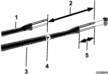
-
Use a piece of tape to mark the length of the old liquid and air tubes onto the new tube assembly.
-
At the new tube assembly, add 26 cm (10 inches) length from the mark that you made in step 7, mark the tube assembly, and cut the tubes at the second (longer) mark (Figure 22).
-
If the old liquid and air tubes are marked with a cable tie, mark the new tube assembly with a cable tie; otherwise skip to step 10.
Note: You no longer need the old liquid and air tubes.
-
Remove 77 to 102 mm (3 to 4 inches) of the sheathing from around each end of the tube assembly (Figure 22).
-
Repeat steps 1 through 10 for the liquid and air tubes at the other side of the machine.
Installing the New Tube Assembly
-
Slip the blue compression nut over the ends of blue tube and the white compression nut over the clear tube (Figure 23).
-
Align the end of the clear tube with the white compression nut to the white fitting of the foam-marker nozzle, and tighten the compression nut by hand (Figure 23).
-
Align the end of the blue tube with the blue compression nut to the blue fitting of the foam-marker nozzle, and tighten the compression nut by hand (Figure 23).
-
Route the tube assembly along rear side of the upper support pole of the outer-spray section as shown in Figure 24.
Important: If the tube assembly is installed at the wrong side of the upper support pole, the tubes will be pinched between the cradle and the outer-spray section when the booms are in the transport position.
-
Secure the tube assembly to the hole in the nozzle support with a cable tie as shown in Figure 25.
-
Secure the tube assembly to the outer-spray section with cable ties as shown in Figure 24.
-
Loosely secure the free end of the tube assembly to the outer-spray section.
-
Repeat steps 1 through 6 for the tube assembly at the other side of the machine.
Disconnecting the Optional Ultra Sonic Boom Leveling Kit
-
Disconnect 3-pin connector of the wire harness for the ultra sonic boom leveling kit from the 3-socket connector of the machine wire harness (Figure 26).
-
Repeat step 1 for the 3-pin connector of the ultra sonic boom wire harness at the other side of the machine.
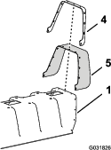
Removing the Center-Section Cover (11-nozzle) of the Optional Covered-Boom Kit
-
While supporting the center-section cover (11–nozzle), remove the 4 flange-head bolts (5/16 x 1-1/4 inches) and 2 cover straps that secure the cover to the cover-support bracket (Figure 27).
-
Remove the center-section cover from the machine (Figure 28).
Note: Retain the cover for assembly, cover straps, and flange-head bolts for installation in steps 1 and 2 of Installing the Center-Section Cover.
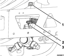
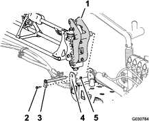
Disconnecting the Pressure-Sense Tube for the Dash Gauge
Disconnecting the Pressure-Sense Tube for the Dash Gauge
Note: If your machine is equipped with an optional spray gun kit, refer to Disconnecting Pressure-Sense Tube and Supply Hose.
Disconnecting Pressure-Sense Tube and Supply Hose
-
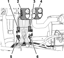
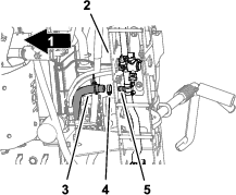
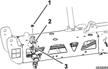
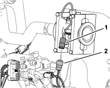
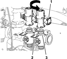
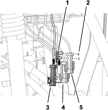
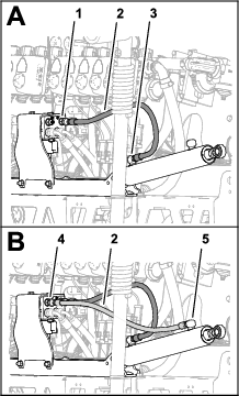
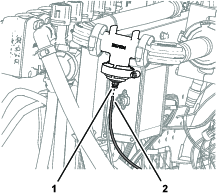
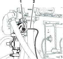
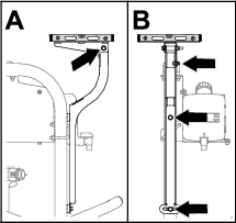
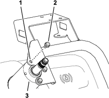
Press in the collar for the tube coupler in the 90° elbow of the right spray-section valve (Figure 30).
-
Pull the pressure-sense tube for the dash gauge out of the tube coupler (Figure 30).
Note: Do not remove the 90° elbow for the shutoff valve for the supply hose of the hose reel from the flange of the right boom-section valve.
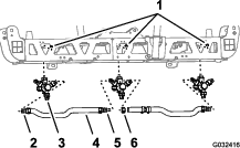
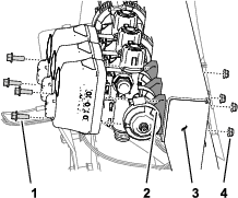
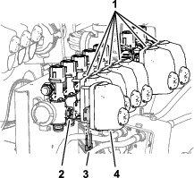
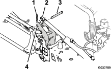
Disconnecting the Sprayer Valve Connectors
-
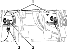
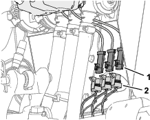
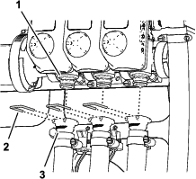
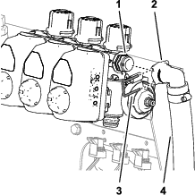
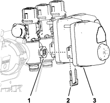
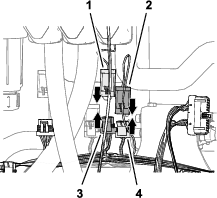
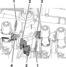
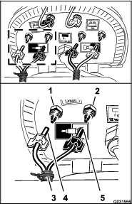
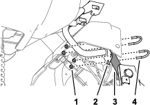
Disconnect the 3-socket connector labeled LEFT SPRAY VALVE, CENTER SPRAY VALVE, and RIGHT SPRAY VALVE of the machine wire harness from the 3-pin connectors of the 3 spray-valve actuators (Figure 31).
-
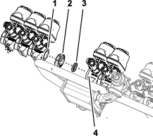
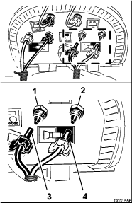
Disconnect the 4-socket connector of the machine wire harness labeled RATE VALVE from the 4-pin connector of the rate-valve actuator (Figure 32).
-
Disconnect the 3-socket connector of the machine wire harness labeled MASTER SPRAY VALVE from the 3-pin connector of the master spray-valve actuator (Figure 32).
Removing the Rate-Control Switch
Parts needed for this procedure:
| Cable tie | 1 |
| Switch plug | 1 |
-
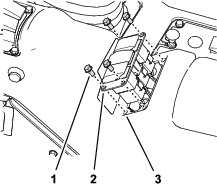
Remove the 4 flange head screws (1/4 x 1/2 inch) that secure the 3-switch panel to the control console (Figure 33).
-
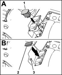
Squeeze the lock tabs of the rate-control switch together and push up the switch out of the 3-switch panel (Figure 34).
-
Disconnect the 8-socket connector of the machine wire harness (labeled Rate Switch) from the 8-pin connector of the switch (Figure 33).
Note: You no longer need the rate switch that you removed from the machine.
-
Route the branch of the front harness for the rate switch through the opening in the 3-switch panel and secure the wiring branch against an adjacent wire branch with a cable tie.
-
Assemble the 3-switch panel to the control console (Figure 34) with the 4 flange head screws (1/4 x 1/2 inch) that you removed in step 1.
-
Align the switch plug to the opening in the 3-switch panel where you removed the rate switch (Figure 33).
-
Insert the switch plug into the 3-switch panel until the plug snaps into the panel securely (Figure 33).
Removing the Spray Sections
Removing the Spray-Section Hoses
-
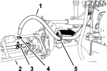
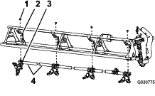
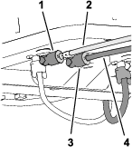
At the outer spray section, remove the hose clamp that secures the sprayer-section hose to the barbed T-fitting (Figure 35).
-
Remove the hose from the T-fitting (Figure 35).
-
Remove the free end of the hose from the R-clamp (Figure 35).
-
Repeat steps 1 through 3 for the supply hose at the other outer-spray section.
-
Under the center-spray section, remove the hose clamp that secures the supply hose for the center-spray section to the barbed T-fitting (Figure 36).
-
Remove the retainers that secure the quick couplers of the left, center, and right supply hoses from the quick couplers if the spray-section valves (Figure 37).
Note: Retain the retainers for installation in Assembling the Hoses to Nozzle Valves 7 through 10.
-
Remove the left, center, and right section-supply hoses from the quick couplers of the spray-section valves, and remove the hoses from the machine (Figure 37).
Note: You no longer need the hoses for the left, center, and right section-supply hoses.
Removing the Extend and Retract Hoses for the Lift Cylinder
-
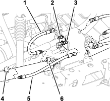
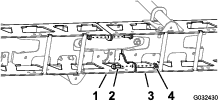
Remove the hoses from the extend ports of the left and right lift cylinders (Figure 39).
-
Remove the hoses from the ports of the C2 and C4 of the lift-cylinder manifold (Figure 39).
-
Remove the hoses from the retract ports of the left and right lift cylinders (Figure 39).
-
Remove the hoses from the ports of the C1 and C3 of the lift-cylinder manifold (Figure 39).
Note: You no longer need the hoses.
Removing the Lift Cylinders
Lift equipment capacity: 91 kg (200 lb)
Note: Except where noted, retain all hardware that you remove; you will use the hardware to install the center-boom extension.
-
Use lifting equipment of the specified capacity to support the outer-spray section.
-
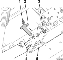
Remove the hairpin and clevis pin that secure the rod end of the lift cylinder to the pivot bracket (Figure 40).
Note: Retain the clevis pin and hairpin for installation in Assembling the Lift Cylinders.
-
Remove the flange locknut (5/16 inch) and flange-head bolt (5/16 x 3/4 inch) that secures the pivot pin to the cylinder mount (Figure 41).
-
Remove the pivot pin and the lift cylinder from the machine (Figure 41).
-
Perform the steps in Removing the Outer-Spray Sections.
Removing the Outer-Spray Sections
Lift equipment capacity: 91 kg (200 lb)
Note: If your machine is equipped with the optional covered-boom kit, leave the covers installed at the outer-spray sections.
Warning
Lifting heavy machines and attachments improperly could result in serious injury or even death.
When lifting heavy machines and attachments, use lifting equipment, such as chains and straps, that is rated for the weight of the equipment.
Note: Except where noted, retain all hardware that you remove; you will use the hardware to install the center-boom extension.
-
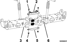
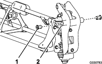
Remove the flange bolt (5/16 x 1 inch) and flange locknut (5/16 inch) securing the pivot pin to the pivot bracket (Figure 42).
-
Remove the pivot pin from the pivot bracket for the center-spray section and the pivot fitting for the outer-spray section (Figure 42).
Note: Retain the flange bolt, flange nut and pivot pin for installation in Removing the Outer-Spray Sections.
-
Separate the outer-spray section from the center-spray section and remove outer section from the machine (Figure 42).
-
Remove the 2 nylon-flange bushings from the pivot fitting of the outer-spray section (Figure 42).
Note: Discard the bushings.
-
Repeat steps 1 through 3 in Removing the Lift Cylinders for the outer-spray section at the other side of the machine.
-
Repeat steps 1 through 4 of this section for the outer-spray section at the other side of the machine.
Removing the Section-Lift Manifold from the Center-Spray Section
-
Remove the section-lift manifold from the cylinder mount as follows:
-
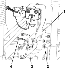
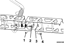
For machines without the optional ultra sonic boom leveling kit: remove the 2 flange locknuts (5/16 inch) and 2 flange-head bolts (5/16 x 1 inch) that secure the support bracket for the section-lift manifold to the cylinder mount, and separate the manifold and bracket from the cylinder mount (Figure 43).
-
For machines with the optional ultra sonic boom leveling kit: Remove the 2 flange locknuts (5/16 inch) and 2 flange-head bolts (5/16 x 1 inch) that secure the support bracket for the section-lift manifold and the TEC controller bracket to the cylinder mount, and separate the manifold and bracket from the cylinder mount (Figure 44).
-
-
Support the section-lift manifold by tying it to the sprayer valve mount bracket with a piece of rope.
Note: Retain the support bracket and lift manifold, bolts, and nuts for installation in Assembling the Lift Cylinder Manifold to the Cylinder Mount.
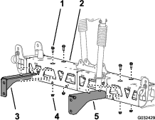
Removing the Center-Spray Section
Lifting-equipment capacity: 41 kg (90 lb)
-
If your machine is equipped with the optional covered-boom kit, remove the cover from the center-spray sections.
-
Support the center-spray section with lifting equipment with the specified capacity (Figure 45).
-
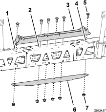
Use a piece of tape to mark the holes where the 4 flange-head bolts (1/2 x 1-1/4 inches) and 4 flange locknuts (1/2 inch) secure the support brackets for the center-spray section to the mounting plate of the machine (Figure 46).
-
Remove the 4 flange-head bolts (1/2 x 1-1/4 inches) and 4 flange locknuts (1/2 inch) that secure the support brackets of the center-spray section to the mounting plate on the frame for the machine, and remove the center-spray section from the machine (Figure 47).
Note: Retain the bolts and locknuts for installation of the new center-spray section.
Installing the Center-Boom Extension
Parts needed for this procedure:
| Flange-head bolt (3/8 x 1 inch) | 2 |
| Flange locknuts (3/8 inch) | 2 |
| Center-boom extension | 1 |
| Cylinder mount (wide) | 1 |
| Tie plate (wide) | 1 |
| Carriage bolt (1/2 x 1-1/4 inches) | 4 |
| Flange locknut (1/2 inch) | 4 |
Removing the Sprayer Nozzles
-
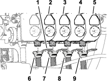
At the center-spray section, remove the flanged locknut that secures the sprayer nozzle to the nozzle mount (Figure 48 and Figure 49).
Note: Retain the locknut for installation in step 6 of Installing the Sprayer Nozzles and Hoses to the Center-Spray Section.
-
Remove the stainless steel screw (#12 x 1-1/4 inches) that secures the upper clamp half and double or single barbed-hose shank (3/4 inch) to the body of the sprayer nozzle, and separate the barbed-hose shank and hose from the nozzle (Figure 50).
Note: The hex-head bolt (5/16 x 3/4 inch—stainless steel) will separate from the upper clamp half when you open the clamp, retain the bolt for installation.
-
Remove the nozzle from the center-spray section (Figure 48 and Figure 49).
-
Repeat steps 1 and 2 for the other 2 sprayer nozzles.
Note: Retain the sprayer nozzles, stainless steel screws, and hex-head bolts for installation in step 6 and 7 of Assembling the Sprayer Nozzles and Hoses for the Center-Spray Section.
-
Remove the hoses (3/4 inch inside diameter), barbed-hose shanks, clamps and barbed T-fitting from the center-spray section (Figure 48).
Note: You no longer need the hose, hose shanks, clamps, and T-fitting.
Removing the Support Brackets from the Center-Spray Section
Lifting-equipment capacity: 41 kg (90 lb)
-
Support the center-spray section with lifting equipment with the specified capacity.
-
Remove the 2 flange-head bolts (3/8 x 1 inch) and 2 flange locknuts (3/8 inch) that secure the support bracket to the center-spray section, and remove the bracket (Figure 51).
-
Remove the 2 flange-head bolts (3/8 x 1 inch) and 2 flange locknuts (3/8 inch) that secure the other support bracket to the center-spray section, and remove the bracket (Figure 51).
Note: Retain the support brackets, bolts, and locknuts for installation in steps 3 and 4 of Assembling the Support Brackets to the Center-Spray Section.
Separating the Center-Spray Section Trusses
-
Remove the 2 flange head bolts (3/8 x 1 inch) and 2 locknuts (3/8 inch) that secure the vertical flanges of the left and right truss frames (Figure 52).
-
Remove the 2 carriage bolts (1/2 x 1-1/4 inches) and 2 locknuts (1/2 inch) that secure the narrow cylinder mount, left and right truss frames, and narrow tie plate (Figure 53).
Note: Retain the flange-head bolts, carriage bolts, and locknuts for installation in steps 2 and 7 of Installing the Center-Boom Extension. You no longer need the narrow cylinder mount and narrow tie plate.
-
Separate the left and right truss frames.
Installing the Center-Boom Extension
-
Align the holes in vertical flanges of the center-boom extension with the holes in the truss frame (Figure 54).
-
Loosely assemble the center-boom extension to the truss frame (Figure 54) with the 2 flange-head bolts (3/8 x 1 inch) and 2 flange locknuts (3/8 inch) that you removed in step 1 of Separating the Center-Spray Section Trusses.
-
Align the holes in vertical flanges of the center-boom extension with the holes in the other truss frame (Figure 54).
-
Loosely assemble the center-boom extension to the other truss frame (Figure 54) with the 2 flange-head bolts (3/8 x 1 inch) and 2 flange locknuts (3/8 inch) from the GeoLink spray system finishing kit (Figure 54).
-
Align the holes in the cylinder mount with the holes at the centerline of the truss frame and center-boom extension (Figure 55).
-
Insert the tie plate into the truss frame and center-boom extension and align the hole in the tie plate with the holes at the centerline of the trusses and boom extension (Figure 55).
-
Assemble the cylinder mount, trusses, center-boom extension, and tie plate with the 2 carriage bolt (1/2 x 1-1/4 inches) and 2 flange locknut (1/2 inch) that you removed in step 2 of Separating the Center-Spray Section Trusses, and the 4 carriage bolt (1/2 x 1-1/4 inches) and 4 flange locknut (1/2 inch) from the GeoLink spray system finishing kit (Figure 55).
-
Torque the 3/8 inch flange head bolts and flange locknuts to 37 to 45 N∙m (27 to 33 ft-lb).
-
Torque the 1/2 inch flange locknuts to 91 to 113 N∙m (67 to 83 ft-lb).
Installing the Mount Brackets and Sprayer Nozzles to the Center-Spray Section
Parts needed for this procedure:
| Sprayer nozzle | 2 |
| Hose assembly (sprayer valve 5 or 6) | 2 |
| Flange locknut (5/16 inch) | 2 |
Assembling the Support Brackets to the Center-Spray Section
Lifting-equipment capacity: 55 kg (120 lb)
-
Support the center-spray section with lifting equipment with the specified capacity.
-
Align the holes in the right support bracket to the holes in the right truss frame as shown in Figure 56.
-
Assemble the right support bracket to the right truss frame (Figure 56) with the 2 flange-head bolts (3/8 x 1 inch) and 2 flange locknut (3/8 inch) that you removed in steps 2 and 3 of Removing the Support Brackets from the Center-Spray Section.
-
Repeat steps 2 and 3 for the left support bracket at the left truss frame (Figure 56).
-
Torque the flange head bolts and flange nuts to 37 to 45 N∙m (27 to 33 ft-lb).
Assembling the Sprayer Nozzles and Hoses for the Center-Spray Section
-
Using lifting equipment, raise the new center-spray section to a comfortable working height.
-
Working with the 2 sprayer nozzle from the GeoLink spray system finishing kit, remove the stainless steel screw that secures the upper clamp half to the saddle (Figure 57).
-
Locate the hole in the side of single barbed-hose shank at the end of the hose 25 cm (10 inches) of the hose assembly (sprayer valve 5 or 6) for the center-spray section (Figure 57 and Figure 58).
-
Align the transfer tube in the saddle of a sprayer nozzle (Figure 57) with the hole in the side of the single barbed-hose shank (1/2 inch).
-
Close the upper clamp half around the barbed-hose shank and secure the clamp half and spray-nozzle body (Figure 57) with the stainless steel screw (#12 x 1-1/4 inches); torque the stainless steel screw to 14 to 18 N∙m (20 to 25 in-lb).
Important: Do not tighten the stainless steel screw more than the torque specification in step 5.
Note: Ensure that the hex-head bolt (5/16 x 3/4 inch) is seated in the recess in the upper clamp half when closing the clamp.
-
Working with the sprayer nozzle, hex-head bolt, and stainless steel screw that you removed in steps 1 and 2 of Removing the Sprayer Nozzles, repeat steps 3 through 5 to the single barbed-hose shank (Figure 57 and Figure 58) at the end of the other hose 25 cm (10 inches).
-
Working with the 2 sprayer nozzles that you removed in step 4 of Removing the Sprayer Nozzles, repeat steps 3 through 5 to the single barbed-hose shanks of the other hose assembly (sprayer valve 5 or 6) for the center-spray section (Figure 57 and Figure 58).
Installing the Sprayer Nozzles and Hoses to the Center-Spray Section
-
Route the hose 13 mm (10 inches) and nozzle assembly between the truss braces of the outer truss (Figure 59).
-
Route the hose and nozzle above the truss brace and outward to the outboard nozzle mount (Figure 59).
-
Align the hex-head bolt (5/16 x 3/4 inch) of the sprayer nozzle through the hole in the nozzle mount and loosely secure the nozzle to the mount with a flange locknut (5/16 inch) from the GeoLink spray system finishing kit (Figure 60).
-
Route the other hose 13 mm (10 inches)and nozzle assembly between the s truss braces of the outer truss (Figure 59).
-
Route the hose and nozzle above the truss brace and inward to the inboard nozzle mount (Figure 59).
-
Align the hex-head bolt (5/16 x 3/4 inch) of the sprayer nozzle through the hole in the nozzle mount (Figure 60) and loosely secure the nozzle to the mount with a flange locknut (5/16 inch) that you removed in steps 1 and 4 of Removing the Sprayer Nozzles.
-
Torque the flange locknut to 1978 to 2542 N∙cm (175 to 225 in-lb).
-
Route the hose and barbed coupler 13 x 810 mm (1/2 x 32 inches) to the side of the center-spray section with the left and right support brackets (Figure 59).
-
Repeat steps 1 through 8 for the other hose and nozzle assembly at the other outer truss (Figure 59 and Figure 60).
Removing the Boom-Section Valves
Parts needed for this procedure:
| Cap (quick coupler) | 3 |
| Retainer | 3 |
Removing the Section Bypass Hose
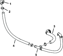
-
Remove the upper end of the bypass hose as follows:
-
For machines without the optional hand wand kit or optional electric hose reel kit, remove the small retainer that secures the quick-disconnect fitting of the bypass hose to the quick-disconnect fitting of the right section-bypass valve (Figure 61).
-
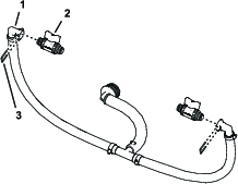
For machines with the optional hand wand kit or optional electric hose reel kit, perform the following steps:
-
Remove the retainer that secures the quick connect fitting of the shutoff valve to the quick-disconnect socket of the right section-bypass valve, and separate the valve from the socket (Figure 62).
-
Remove the retainer that secures the quick connect fitting of the shutoff valve to the quick-disconnect socket of the 90° barbed fitting, and separate the valve from the socket (Figure 62).
Note: Retain the shutoff valve and retainers for installation in Assembling the Shutoff Valve to the Bypass Hose.
-
-
-
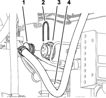
Remove the large retainer that secures the 90° barbed fitting at the lower end of the bypass hose to the bulkhead fitting of the sprayer tank (Figure 63).
Note: Retain the large retainer for installation in Assembling the Bypass Hoses to the Tank.
-
Remove the bypass hose from the machine.
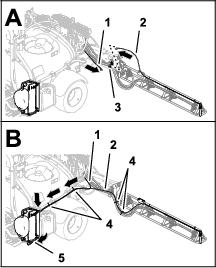
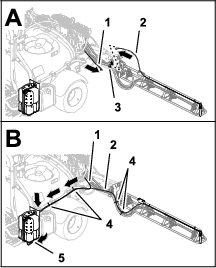
Note: You no longer need the bypass hose and the small retainer.
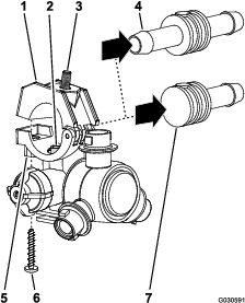
Positioning the Bypass Valves—Machines without the Optional Hand Spray Wand Kit or the Optional Electric Hose Reel Kit
-
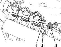
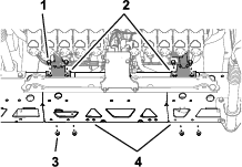
Remove the 3 retainers that secure the 3 valve actuators to the left, center, and right section valves (Figure 64).
-
Remove the valve actuators from the left, center, and right section valves (Figure 64).
-
Remove the retainer that secures the cap to the quick disconnect fitting of the bypass valve, and remove the cap (Figure 65).
Note: You no longer need the cap.
-
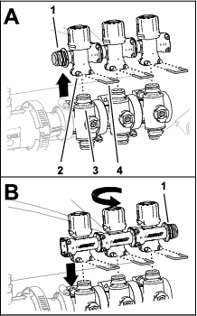
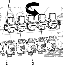
Remove the 3 retainers that secure the 3 bypass valves to the left, center, and right section valves (Figure 66).
-
Lift the bypass valves from the section valves (Figure 66).
-
Rotate the bypass valves 180° and assemble them onto the quick disconnect fittings of the section valves (Figure 66).
-
Secure the 3 bypass valves to the section valves with the 3 retainers that you removed in step 4 (Figure 66).
-
Assemble plug into the quick connect socket of the bypass valve (Figure 67).
-
Secure the plug to the quick connect socket with the retainer that you removed in step 3 (Figure 67).
-
Assemble the 3 valve actuators onto the left, center, and right section valves (Figure 64) with the retainers that you removed in step 1.
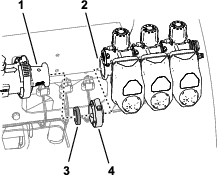
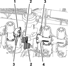
Removing the Section Valves from the Manifold Mount
Note: You will add the section valves to the valves for the 10-valve GeoLink sprayer system in Assembling the 3 Section Valves to the Valve Mount.
-
Remove the 2 flange-head bolts (1/4 x 3/4 inch) and 2 locknuts (1/4 inch) that secure the left boom-section valve to the manifold mount (Figure 68).
Note: You no longer need the 2 flange head bolts and locknuts.
-
Remove the 2 flange-head bolts (1/4 x 3/4 inch) and 2 locknuts (1/4 inch) that secure the right boom-section valve to the manifold mount (Figure 68).
-
Remove the flange clamp 40 to 64 mm (1-9/16 to 2-1/2 inches) and gasket 25 x 35 mm (1 x 1-3/8 inches) that secures the flange of the left section valve to the adapter (Figure 68).
Note: Retain the 2 flange-head bolts, 2 locknuts, flange clamp and gasket for installation in Assembling the 3 Section Valves to the Valve Mount.
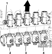
-
Remove the 3 section valves from the machine (Figure 69).
-
Remove the decals from the actuators of the 3 section valves (Figure 70).
-
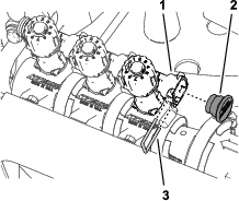
Remove the flange clamp 51 mm (2 inches) and gasket 38 mm (1-1/2 inches) that secure the flange of the adapter to the flange of the flow meter (Figure 71).
Note: Retain the flange clamp and gasket for installation in Assembling the Manifold to the Flow Meter.
Installing the Flow Meter Support Clamps
Parts needed for this procedure:
| Flow meter mount | 1 |
| Support-clamp half | 4 |
| Bolt (1/4 x 4-1/2 inches) | 4 |
| Flange locknuts (1/4 inch) | 4 |
Removing the Section-Valve Bracket
-
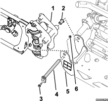
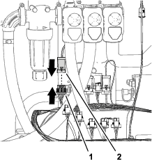
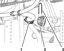
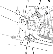
Disconnect the 3-socket connector of the machine wire harness labeled FLOW METER from the 3-pin connector of the flow meter (Figure 72).
-
Remove the 2 push-in fasteners of the machine wire harness from the bottom flange of the section-valve bracket (Figure 72).
-
Remove the 4 flange-head screws (5/16 x 3/4 inch) that secure the section-valve bracket from the valve mount, and remove the valve bracket from the machine (Figure 73).
Note: Retain the 4 flange-head screws for installation in Installing the Flow Meter Mount and Clamps; you no longer need the section-valve bracket.
Installing the Flow Meter Mount and Clamps
-
Align the holes in the flow-meter bracket with the holes in the valve mount (Figure 74).
-
Assemble the flow-meter bracket to the valve mount with the 4 flange-head screws that you removed in step 3 of Removing the Section-Valve Bracket, and torque the screws to 1978 to 2542 N∙cm (175 to 225 in-lb).
-
Align a 2 support-clamp halves between the flow meter and the flow-meter bracket, and align the holes in the clamp halves with the holes in the bracket (Figure 75).
-
Align a support clamp half at the rear side of the flow meter with 1 of the clamp halves that you assembled in step 3 (Figure 75).
-
Assemble the pair of clamp halves to the flow meter bracket (Figure 75) with 2 bolts (1/4 x 4-1/2 inches) and 2 flange locknuts (1/4 inch).
-
Repeat steps 4 and 5 at the other clam half that you assembled in step 3.
-
Torque the bolts and nuts to 1017 to 1243 N∙cm (90 to 110 in-lb).
Assembling the Wire Harness to the Machine
Parts needed for this procedure:
| Rear wire harness | 1 |
| Cable tie | 7 |
Routing Kit Wire Harness
-
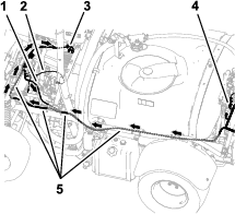
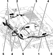
Locate the 84 cm (33 inch) wire-harness branch, 60 cm (23-1/2 inch) wire-harness branch, and 66 cm (26 inch) wire-harness branch of the kit wire harness (Figure 76 and Figure 77).
-
Route the 84 cm (33 inch), 60 cm (23-1/2 inch), and 66 cm (26 inch) wire-harness branches of the kit wire harness to the left side of the machine along the machine wire harness (Figure 78 and Figure 79).
-
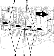
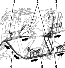
Route the 84 cm (33 inch), 60 cm (23-1/2 inch), and 66 cm (26 inch) wire-harness branches of the kit wire harness forward along the left frame channel (Figure 81 and Figure 82).
-
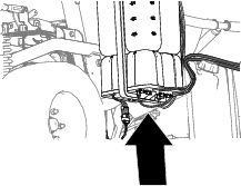
Route the 84 cm (33 inch), 60 cm (23-1/2 inch), and 66 cm (26 inch) wire-harness branches of the kit wire harness along the machine wire harness, outboard of the parking-brake assembly (Figure 83).
-
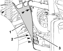
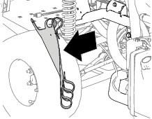
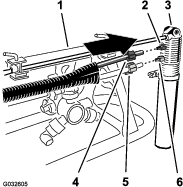
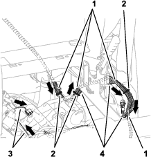
Route the 84 cm (33 inch), 60 cm (23-1/2 inch), and 66 cm (26 inch) wire-harness branches of the kit wire harness across the shock-support tube as shown in Figure 84.
-
Secure the kit wire harness to the machine wire harness as shown in Figure 82, Figure 83, and Figure 84.
-
At the back of the machine, route the 89 cm (35 inch) wire-harness branch forward of the lift manifold, and to the right of the flow meter as shown in Figure 85.
-
Route the 102 cm (40 inch) wire-harness branch rearward of the lift manifold, and to the right as shown in Figure 85.
Connecting the Left, Center, and Right Spray-Valve Connectors
-
Connect the 3-pin connector of the 89 cm (35 inch) wire-harness branch labeled LEFT SPRAY to the 3-socket connector of the machine wire harness labeled LEFT SPRAY VALVE (Figure 86).
-
Connect the 3-pin connector kit wire harness labeled CENTER SPRAY to the 3-socket connector of the machine wire harness labeled CENTER SPRAY VALVE (Figure 86).
-
Connect the 3-pin connector of the kit wire harness labeled RIGHT SPRAY to the 3-socket connector of the machine wire harness labeled RIGHT SPRAY VALVE (Figure 86)
-
Insert the push-in fastener of the kit wire harness into the hole in the flange of the flow-meter bracket (Figure 86).
Connecting the Flow Meter, Master Section Valve, and Rate Valves Electrical Connectors
-
Connect the 3-socket electrical connector of the 89 cm (35 inch) wire-harness branch labeled FLOW METER into the 3-pin connector of the flow meter (Figure 87).
-
Connect the 3-pin connector of the 89 cm (35 inch) kit wire-harness branch labeled MASTER VALVE into the 3-socket connector of the machine wire harness labeled MASTER SPRAY VALVE (Figure 88).
-
Connect 3-pin connector of the actuator for the master-spray valve into the 3-socket connector of the 89 cm (35 inch) kit wire-harness branch labeled MASTER VALVE (Figure 88).
-
Connect the 4-pin connector of the actuator for the rate valve into the 4-socket connector of the 89 cm (35 inch) kit wire-harness branch labeled RATE VALVE (Figure 89).
Assembling the Flow-Meter Manifold
Parts needed for this procedure:
| Straight hose barb (1 x 2 inches) | 1 |
| Hose clamp (3/4 to 1-1/2 inches) | 3 |
| Hose (1 x 5-3/4 inches) | 1 |
| Manifold | 1 |
| Hose (1 x 16 inches) | 1 |
Assembling the Manifold
-
Assemble hose (1 x 5-3/4 inches) on to the straight hose barb (1 x 2 inches) with a hose clamp (3/4 to 1-1/2 inches), and tighten the clamp by hand (Figure 90).
-
Assemble the other end of the hose (1 x 5-3/4 inches) onto the barbed fitting of the manifold with a hose clamp as shown in Figure 90, and tighten the hose clamp by hand.
-
Assemble the hose (1 x 16 inches) onto the other barbed fitting of the manifold with a hose clamp, and tighten the clamp by hand (Figure 90).
Assembling the Manifold to the Flow Meter
-
Assemble the straight hose barb (1 x 2 inches) to the flange of the flow meter with the gasket 38 mm (1-1/2 inches) and flange clamp 51 mm (2 inches) that you removed in step 6 of Removing the Section Valves from the Manifold Mount.
-
Tighten the flange clamp by hand (Figure 91).
Installing the Bypass Hoses to the Tank
Parts needed for this procedure:
| 90° quick-connect fitting (socket—1 inch) | 2 |
| Hose (1 x 26 inches) | 2 |
| Hose clamp (3/4 x 1-1/5 inches) | 5 |
| T-fitting (1 x 1 x 1 inch) | 1 |
| 90° barbed fitting and hose assembly | 1 |
| Shutoff valve | 1 |
Assembling the Bypass Hoses
-
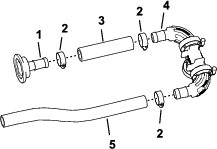
Assemble the 90° quick-connect fitting (socket—1 inch) into the hose (1 x 26 inches) and secure the hose to the fitting with a hose clamp as shown in Figure 92.
-
Assemble the free end of the hose onto the T-fitting as shown in Figure 92 and secure the hose to the fitting with a hose clamp.
-
Repeat steps 1 through 2 for the other 90° barbed fitting, quick-connect fitting, and hose.
-
Assemble the 90° barbed fitting and hose assembly onto the T-fitting and secure the hose to the fitting with a hose clamp (Figure 92).
Assembling the Shutoff Valve to the Bypass Hose
-
As shown in Figure 93, remove the retainer from the 90° quick-connect fitting that you assembled in Assembling the Bypass Hoses.
-
Assemble the shutoff valve into the quick-disconnect fitting socket (Figure 93).
-
Secure the valve to the fitting with the retainer that you removed in step 1.
-
Assemble the shutoff valve and retainer that you removed in step 1 of Removing the Section Bypass Hose to the other quick-disconnect fitting socket (Figure 93).
Assembling the Bypass Hoses to the Tank
-
Align the bypass hose assembly to the sprayer tank (Figure 94).
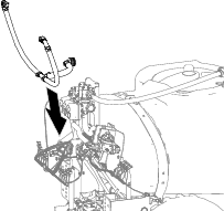
-
Assemble the 90° barbed fitting to the bulkhead fitting of the sprayer tank and secure the fittings with the retainer that you removed in step 2 of Removing the Section Bypass Hose.
Installing the Modified Center-Spray Section
Lifting-equipment capacity: 55 kg (120 lb)
-
Using lifting equipment with the specified lift capacity, raise the center-spray section and align the holes in the support bracket for the spray section (Figure 95) with the holes in the mounting plate for the frame of the machine that you identified in step 3 of Removing the Center-Spray Section.
-
Assemble the center-spray section to the mounting channels (Figure 95) with the 4 flange-head bolt (1/2 x 1-1/4 inches) and 4 flange locknut (1/2 inch) that you removed in step 4 in Removing the Center-Spray Section.
-
Torque the nuts and bolts to 91 to 113 N∙m (67 to 83 ft-lb).
Assembling the Lift Cylinder Manifold to the Cylinder Mount
-
Untie the lift manifold from the valve-mount bracket.
-
Assemble the section lift manifold to the cylinder mount as follows:
-
For machines without the optional ultra sonic boom leveling kit:
-
Align the holes in the support bracket for the section-lift manifold with the holes in the cylinder mount (Figure 96).
-
Assemble the support bracket to the cylinder mount (Figure 96) with the 2 flange-head bolt (5/16 x 1 inch) and flange locknut (5/16 inch) that you removed in step 1 of Removing the Section-Lift Manifold from the Center-Spray Section.
-
-
For machines with the optional ultra sonic boom leveling kit:
-
Align the holes in the support bracket for the section-lift manifold and the TEC controller bracket with the holes in the cylinder mount.
-
Assemble the support bracket and TEC bracket to the cylinder mount (Figure 97) with the 2 flange-head bolt (5/16 x 1 inch) and flange locknut (5/16 inch) that you removed in step 1 of Removing the Section-Lift Manifold from the Center-Spray Section.
-
-
-
Torque the bolts and nuts to 1978 to 2542 N∙cm (175 to 225 in-lb).
Installing the Valve Mount and Sprayer Valves
Parts needed for this procedure:
| Valve mount and sprayer-valve assembly | 1 |
| Bolt (4 x 10 mm) | 3 |
| ASC 10 sprayer controller | 1 |
| Flange locknut (4 mm) | 3 |
| Cap (quick-disconnect fitting) | 2 |
| Flange-head bolts (5/16 x 3/4 inch) | 8 |
| Flange locknuts (5/16 inch) | 8 |
| Hose clamp | 1 |
| Push-in fastener (cable tie) | 1 |
| Push-in fastener (connector anchor) | 3 |
Assembling the Sprayer Controller to the Valve Mount
-
Align the ASC 10 sprayer controller to the forward side of the valve mount with the 4-pin connector outward (Figure 98).
-
Assemble the sprayer controller to the valve mount (Figure 98) with the 3 bolts (4 x 10 mm) and 3 flange locknuts (4 mm).
Note: Do not use the upper outboard hole in the ASC 10 sprayer controller.
-
Torque the bolts and nuts to 234 to 286 N∙cm (21 to 25 to in-lb).
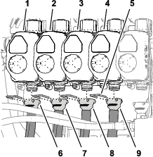
Positioning the Bypass Valves—Machines with the Optional Hand Wand Kit or the Optional Electric Hose Reel Kit
-
Remove the retainers that secure the valve actuators for nozzle valves 1 through 7 (Figure 99).
-
Remove the valve actuators from nozzle valves 1 through 7 (Figure 99).
-
Remove the retainers that secures the plugs in the sockets of the quick disconnect fitting at the nozzle valve 5 and nozzle valve 6, and remove the plugs (Figure 100).
Note: You no longer need the plugs; retain the retainers for installation in Installing the Section Bypass Hoses—Machines with the Optional Hand Wand Kit or the Optional Electric Hose Reel Kit.
-
Remove the retainers that secure the bypass valves to nozzle valves 1 through 7 (Figure 101).
-
Lift the bypass valves from the nozzle valves 1 through 5 (Figure 101).
-
Rotate the bypass valves 180° and assemble them onto the quick disconnect fittings of the section valves (Figure 102).
-
Secure the bypass valves to the section valves with the retainers (Figure 102) that you removed in step 4.
-
Repeat steps 5 through 7 for the bypass valves of nozzle valve 6 and nozzle valve 7 (Figure 103).
-
Assemble the caps onto the quick disconnect fittings of the bypass valves for nozzle-valve 5 and nozzle-valve 6 with the retainers provided with the caps (Figure 102).
-
Assemble the valve actuators onto the nozzle valves 1 thought 7 (Figure 99) with the retainers that you removed in step 1.
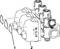
Assembling the 3 Section Valves to the Valve Mount
-
Assemble the 3 section valves (Figure 105) that you removed in step 8 of Removing the Section Valves from the Manifold Mount onto the flange of valve 7 of the sprayer valve assemble with the flange clamp and gasket that you removed in step 4 of Removing the Section Valves from the Manifold Mount.
Important: The left, center, and right section valves are identified in the GeoLink sprayer system as follows: left section valve—nozzle valve 8, center section valve—nozzle valve 9, and right section valve—nozzle valve 10.
-
Secure the socket of the quick-disconnect coupling for bypass valve of nozzle valve 8 to the quick-disconnect coupling for bypass valve of nozzle valve 7 with the retainer that you removed in step 8 of Removing the Section Valves from the Manifold Mount.
-
Assemble nozzle valve 10 to the valve mount (Figure 107 or Figure 108) the with the 2 flange-head bolt (1/4 x 3/4 inch) and 2 locknut (1/4 inch) that you removed in step 2 of Removing the Section Valves from the Manifold Mount.
-
Torque the flange-head bolts and locknuts to 1017 to 1243 N∙m (90 to 120 in-lb).
Assembling the Valve Mount and Sprayer Valve Assembly to the Machine
Lifting-equipment capacity: 23 kg (50 lb)
-
Using lifting equipment with the specified capacity, lift the valve mount and sprayer valve assembly and align it over the center-spray section (Figure 109).
-
Align the holes on the mount bracket of the valve mount to the holes on the truss frame of the center sprayer section (Figure 110).
-
Assemble the valve mount to the truss frame (Figure 110 and Figure 111) with 4 bolts (5/16 x 3/4 inch) and 4 flange locknuts (5/16 inch).
-
Repeat steps 2 through 3 for the other mount bracket of the valve mount at the other truss frame.
-
Torque the flange-head bolts and flange locknuts to 1978 to 2542 N∙cm (175 to 225 in-lb).
Assembling the Hose to the Sprayer Valve Manifold
-
Assemble the hose (1 x 16 inches) over the 90° flange fitting (1 inch) as shown in Figure 112.
-
Secure the hose to the flange fitting with a hose clamp (Figure 112).
-
Assemble the cable tie/push-in fastener into the hole at the top of the valve mount as shown in Figure 112.
-
Secure the cable tie/push-in fastener (Figure 112) around the hose (1 x 16 inches).
Installing the Section Bypass Hoses—Machines without the Optional Hand Wand Kit or the Optional Electric Hose Reel Kit
-
Remove the retainers from the sockets of the quick-connect fittings that you assembled to the bypass hoses in step 1 of Assembling the Bypass Hoses.
-
Assemble the quick-connect fitting of the bypass hose to the quick disconnect fitting at the bypass valve at nozzle valve 10 (Figure 113).
-
Secure the quick disconnect fittings for the bypass hose and the bypass valve with the retainer (Figure 113).
-
Repeat steps 1 through 3 for the quick disconnect fittings at nozzle valve 1.
Installing the Section Bypass Hoses—Machines with the Optional Hand Wand Kit or the Optional Electric Hose Reel Kit
-
Assemble the quick-disconnect fitting of the bypass-shutoff valve with the quick disconnect fitting (socket) of the bypass valve (Figure 114).
-
Secure the quick disconnect fittings for the bypass-shutoff valve and the bypass valve with the retainer (Figure 114) that you removed in step 3 of Positioning the Bypass Valves—Machines with the Optional Hand Wand Kit or the Optional Electric Hose Reel Kit.
-
Repeat steps 1 and 2 for the bypass-shutoff valve and the bypass valve at the other side of the machine.
Installing the Nozzle Valve Electrical Connectors
-
Assemble the connector anchor push-in fasteners onto the holes in the valve mount (Figure 115).
-
Connect 3-socket connector (Figure 116) of the 89 cm (35 inch) kit wire-harness branch labeled NOZZLE VALVE 1) into the 3-pin connector of the left most valve actuator (position 1).
Note: The valve actuator positions 1 through 10 are arranged from left to right when standing behind the machine.
-
Connect 3-socket connector (Figure 116) of the 89 cm (35 inch) kit wire-harness branch labeled NOZZLE VALVE 2) into the 3-pin connector of the valve actuator (position 2).
-
Connect the remaining 3-socket connectors of the 89 cm (35 inch) kit wire-harness branch into the 3-pin connector of the valve actuators (Figure 116).
Note: Ensure that the 3-socket connector are connected to the related valve actuator position.
Assembling the Boom-Lift Cylinders
Parts needed for this procedure:
| Hydraulic hose (1/4 x 24-3/4 inches) | 4 |
Assembling the Lift Cylinders
-
Align the fixed end of the lift cylinder that you removed in step 3 of Removing the Lift Cylinders to the 16 mm (5/8 inch) hole in the cylinder mount (Figure 117).
Note: Ensure that the extend and retract ports of the cylinder align up.
-
Assemble the cylinder to the cylinder mount with the pivot pin, flanged-head bolt, and flange nut (Figure 117).
-
Torque the bolt and nut to 1978 to 2542 Ncm (175 to 225 in-lb).
-
Repeat steps 1 through 3 for the other lift cylinder at the other side of the cylinder mount.
Installing the Lift-Cylinder Hoses
-
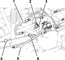
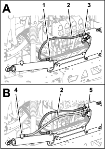
Loosely assemble a new hydraulic hose (1/4 x 24-3/4 inches) between the extend port of the left boom-lift cylinder and port C3 of the boom-lift manifold (Figure 118).
-
Loosely assemble a new hydraulic hose (1/4 x 24-3/4 inches) between the retract port of the left boom-lift cylinder and port C4 of the boom-lift manifold (Figure 118).
-
Loosely assemble a new hydraulic hose (1/4 x 24-3/4 inches) between the extend port of the right boom-lift cylinder and port C1 of the boom-lift manifold (Figure 119).
-
Loosely assemble a new hydraulic hose (1/4 x 24-3/4 inches) between the retract port of the right boom-lift cylinder and port C2 of the boom-lift manifold (Figure 119).
-
Torque the hose fittings at the extend and retract ports of the lift cylinders (Figure 118 and Figure 119) to 21 to 26 N∙m (15 to 19 ft-lb).
-
Torque the swivel nuts of the hoses at the boom-lift manifold (Figure 118 and Figure 119) to 24 to 30 N∙m (17 to 22 ft-lb).
Installing the Outer-Spray Sections
Parts needed for this procedure:
| Nylon-flange bushing | 4 |
| Cable tie | 1 |
| Supply-hose assembly 188 cm (74 inches) | 1 |
| Supply-hose assembly 234 cm (92 inches) | 1 |
| Supply-hose assembly 279 cm (110 inches) | 1 |
Removing the Sprayer Nozzles from the Outer-Spray Sections
-
Cut the hose between 2 sprayer nozzles (Figure 120).
-
Remove the flange locknut (5/16 inch) that secures the sprayer nozzle to the nozzle support (Figure 120).
-
Repeat steps 2 and 1 for the other 3 nozzles.
Note: Retain the flange locknut and sprayer nozzle for installation in Installing the Sprayer Nozzles at the Outer-Spray Sections.
Note: Discard the hoses, clamps and T-fitting that you removed from the machine.
-
Repeat steps 2 through 3 at the other outer-spray section.
-
Working with the 8 sprayer nozzles that you removed in step 1, remove the stainless steel screws (#12 x 1-1/4 inches) that secures the upper clamp halves and the double or single barbed-hose shanks (3/4 inch) to the body of each of the sprayer nozzle, and remove the barbed-hose shanks (Figure 121).
Note: The hex-head bolt (5/16 x 3/4 inch—stainless steel) will separate from the upper clamp half when you open the clamp, retain the bolt for installation.
Assembling the Outer-Spray Sections to the Machine
Lift equipment capacity: 91 kg (200 lb)
-
Using lift equipment with the specified capacity, raise the outer boom.
-
Insert a nylon-flange bushing into the 31.8 mm (1-1/4 inches) hole at each side of the pivot fitting (Figure 122).
-
Align the bushings in the pivot fitting with the holes in the flanges of the pivot bracket at the end of the center-spray section (Figure 123).
-
Assemble the pivot fitting to the pivot bracket with the pivot pin, flange bolt (5/16 x 1 inch), and flange locknut (5/16 inch) that you removed in step 2 of Removing the Outer-Spray Sections.
-
Torque the bolt and nut to 1978 to 2542 N∙cm (175 to 225 in-lb).
-
Align the rod end of the lift cylinder with the hole 25 mm (1 inch) in the horn of the pivot fitting (Figure 124).
-
Secure the lift cylinder to the pivot fitting with the clevis pin and hairpin (Figure 124) that you removed in step 2 of Removing the Lift Cylinders.
-
Repeat steps 1 through 7 at the outer-spray section at the other side of the machine.
Installing the Sprayer-Nozzle Hoses
Parts needed for this procedure:
| Supply-hose 279 cm (110 inches) | 2 |
| Supply-hose 234 cm (92 inches) | 2 |
| Supply-hose 188 cm (74 inches) | 4 |
| Supply-hose 81 cm (32 inches) | 2 |
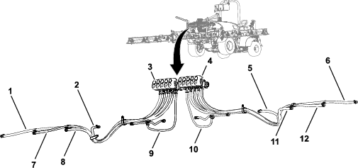
Identifying the Sprayer-Nozzle Hose Positions
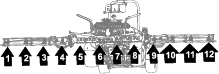
Identify the supply hoses by length (Figure 125) for each of the sprayer-nozzle position as follows:
| Sprayer-nozzle positions—left-spray section | Sprayer-nozzle positions—center-spray section | Sprayer-nozzle positions—right-spray section |
|---|---|---|
| Sprayer nozzle 1 (nozzle valve 1)—supply hose 279 cm (110 inches) | Sprayer nozzles 5 and 6 (nozzle valve 5)—supply hose 81 cm (32 inches) with 2 branch hoses | Sprayer nozzle 9 (nozzle valve 7)—supply hose 188 cm (74 inches) |
| Sprayer nozzle 2 (nozzle valve 2)—supply hose 234 cm (92 inches) | Sprayer nozzles 7 and 8 (nozzle valve 6)—supply hose 81 cm (32 inches) with 2 branch hoses | Sprayer nozzle 10 (nozzle valve 8)—supply hose 188 cm (74 inches) |
| Sprayer nozzle 3 (nozzle valve 3)—supply hose 188 cm (74 inches) | Sprayer nozzle 11 (nozzle valve 9)—supply hose 234 cm (92 inches) | |
| Sprayer nozzle 4 (nozzle valve 4)—supply hose 188 cm (74 inches) | Sprayer nozzle 12 (nozzle valve 10)—supply hose 279 cm (110 inches) |
Note: Refer to Figure 126 in Assembling the Hoses to Nozzle Valves 1 through 4, Figure 127 in Assembling the Hoses to Nozzle Valves 5 and 6, and Figure 128 in Assembling the Hoses to Nozzle Valves 7 through 10 for the nozzle-valve positions.
Assembling the Hoses to Nozzle Valves 1 through 4
-
Assemble the straight barbed fitting of a supply-hose 279 cm (110 inches) onto the coupler of nozzle valve 1 (Figure 126).
Note: Ensure that the barbed fitting is fully seated onto the coupler.
-
Secure the barbed fitting to the coupler with a retainer (Figure 126).
-
Assemble the straight barbed fitting of a supply-hose 234 cm (92 inches) onto the coupler of nozzle valve 2 (Figure 126).
Note: Ensure that the barbed fitting is fully seated onto the coupler.
-
Secure the barbed fitting to the coupler with a retainer (Figure 126).
-
Assemble the straight barbed fitting of a supply-hose 188 cm (74 inches) onto the coupler of nozzle valve 3 (Figure 126).
Note: Ensure that the barbed fitting is fully seated onto the coupler.
-
Secure the barbed fitting to the coupler with a retainer (Figure 126).
-
Assemble the straight barbed fitting of a supply-hose 188 cm (74 inches) onto the coupler of nozzle valve 4 (Figure 126).
Note: Ensure that the barbed fitting is fully seated onto the coupler.
-
Secure the barbed fitting to the coupler with a retainer (Figure 126).
Assembling the Hoses to Nozzle Valves 5 and 6
Note: Supply-hose assembly 81 cm (32 inches) has a T-fitting with 2 branch hoses and 2 single barbed-hose shanks.
-
Assemble the straight barbed fitting of a supply-hose 81 cm (32 inches) onto the coupler of nozzle valve 5 (Figure 127).
Note: Ensure that the barbed fitting is fully seated onto the coupler.
-
Secure the barbed fitting to the coupler with a retainer (Figure 127).
-
Assemble the straight barbed fitting of a supply-hose 81 cm (32 inches) onto the coupler of nozzle valve 6 (Figure 127).
Note: Ensure that the barbed fitting is fully seated onto the coupler.
-
Secure the barbed fitting to the coupler with a retainer (Figure 127).
Assembling the Hoses to Nozzle Valves 7 through 10
-
Assemble the straight barbed fitting of a supply-hose 188 cm (74 inches) onto the coupler of nozzle valve 7 (Figure 128).
Note: Ensure that the barbed fitting is fully seated onto the coupler.
-
Secure the barbed fitting to the coupler with a retainer (Figure 128).
-
Assemble the straight barbed fitting of a supply-hose 188 cm (74 inches) onto the coupler of nozzle valve 8 (Figure 128).
Note: Ensure that the barbed fitting is fully seated onto the coupler.
-
Secure the barbed fitting to the coupler with a retainer (Figure 128).
-
Assemble the straight barbed fitting of a supply-hose 234 cm (92 inches) onto the coupler of nozzle valve 9 (Figure 128).
Note: Ensure that the barbed fitting is fully seated onto the coupler.
-
Secure the barbed fitting to the coupler with a retainer (Figure 128).
-
Assemble the straight barbed fitting of a supply-hose 279 cm (110 inches) onto the coupler of nozzle valve 10 (Figure 128).
Note: Ensure that the barbed fitting is fully seated onto the coupler.
-
Secure the barbed fitting to the coupler with a retainer (Figure 128).
Routing the Supply Hoses to the Sprayer Nozzles
-
Route the hoses for sprayer nozzles 1, 2, 3, and 4 through the R-clamp at the left outboard end of the center-spray section (Figure 129 and Figure 130).
-
Route the hoses for sprayer nozzles 7, 8, 9, and 10 through the R-clamp at the right outboard end of the center-spray section (Figure 129 and Figure 130).
-
Route the supply hoses 279 cm (110 inches) and barbed-hose shanks (3/4 inch) along the spray section to sprayer nozzles 1 and 10 as shown in (Figure 129 and Figure 130).
-
Route the supply hoses 234 cm (92 inches) and barbed-hose shanks (3/4 inch) along the spray section to sprayer nozzles 2 and 9 along the spray section as shown in Figure 129 and Figure 130.
-
Route the supply hoses 188 cm (74 inches) and barbed-hose shanks (3/4 inch) along the spray section to sprayer nozzles 3 and 8 as shown in Figure 129 and Figure 130.
Note: Route the hoses through the lower rear grommets in the tube-frame brackets.
-
Route the supply hoses 188 cm (74 inches) and barbed-hose shanks (3/4 inch) along the spray section to sprayer nozzles 4 and 7 as shown in Figure 129 and Figure 130.
Note: Route the hoses through the lower rear grommets in the tube-frame brackets.
-
Bundle the 4 hoses for the sprayer nozzles together with a cable tie as shown in Figure 130.
Installing the Sprayer Nozzles at the Outer-Spray Sections
-
Align the transfer tube in the saddle of a sprayer nozzle (Figure 131) with the hole in the side of the single barbed-hose shank (1/2 inch).
-
Close the upper clamp half around the barbed-hose shank and secure the clamp half and spray-nozzle body (Figure 131) with the stainless steel screw (#12 x 1-1/4 inches); torque the stainless steel screw to 14 to 18 N∙m (20 to 25 in-lb).
Note: Ensure that the hex-head bolt (5/16 x 3/4 inch) is seated in the recess in the upper clamp half when closing the clamp.
-
Assemble the sprayer nozzles to the outer-spray section as follows:
-
At the nozzle positions 1 and 4, assemble the sprayer nozzle to the nozzle mount (A of Figure 132) with the flange locknut (5/16 inch) that you removed in step 2 of Removing the Sprayer Nozzles from the Outer-Spray Sections.
-
At the nozzle positions 2 and 3, assemble the sprayer nozzle to the nozzle mount (A and B of Figure 132) with the flange locknut (5/16 inch) that you removed in step 2 of Removing the Sprayer Nozzles from the Outer-Spray Sections.
-
-
Torque the flange locknut to 1978 to 2542 N∙cm (175 to 225 in-lb).
-
Repeat steps 1 through 4 for the other sprayer nozzles for the spray section.
-
Repeat steps 1 through 5 to the outer-spray section at the other side of the machine.
Connecting the Kit Wire Harness at the Back of the Machine
Connecting the Wire Harness to the Pressure Transducer and the ASC 10
-
Insert the 3-socket connector 61 cm (24 inch) branch of the kit wire harness labeled PRESSURE TRANSDUCER GREEN WEDGE into the 3-pin connector of the pressure transducer (Figure 133).
-
Insert the 40-socket connector of the 102 cm (40 inch) branch of the kit wire harness into the 40-pin connector if the ASC 10 spray controller (Figure 134).
-
Thread the thumb screw of the 40-socket connector into the ASC 10 connector by hand (Figure 134).
-
Insert the 4-socket connector labeled TO ASC 10 into the 4-pin connector of the ASC 10 spray controller (Figure 135).
Connecting the Pressure-Sense Tube for the Dash Gauge
Connecting the Pressure-Sense Tube for the Dash Gauge
-
Align the end of the pressure-sense tube (plastic) for the pressure gauge in the dash with the locking collar for the tube coupler (Figure 136).
-
Insert the sense tube into the locking collar until the tube is fully seated (Figure 136).
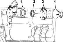
Installing the Pressure Sense-Tube
-
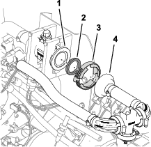
Remove the flange clamp the gasket that secure the plain cap to the flange of nozzle valve 10 (Figure 137).
-
Remove the flange clamp and gasket that secure the cap and tube fitting to the flange of the flow meter manifold (Figure 137).
-
Assemble the plain cap onto the flange of the flow-meter manifold with the flange clamp and gasket that you removed in step 2, and tighten the clamp by hand (Figure 138).
-
Assemble the 90° fitting of the shutoff valve for the optional spray wand kit or the electric hose reel kit onto the flange of nozzle valve 10 with the flange clamp and gasket that you removed in step 1, and tighten the clamp by hand (Figure 139).
-
Align the end of the pressure-sense tube (plastic) for the pressure gauge in the dash with the locking collar for the tube coupler in the 90° fitting of the shutoff valve of the hand spray wand or the electric hose reel kit (Figure 140).
-
Insert the sense tube into the locking collar until the tube is fully seated (Figure 140).
Connecting the Optional Foam-Marker Kit
Parts needed for this procedure:
| Cable tie | 6 |
Routing the Tubing for the Foam-Marker Nozzles
-
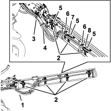
Route the tubes for the foam nozzles at the left- and right-spray section, inboard and through the R-clamp near the pivot point for each outer-spray section (Figure 142).
-
Route the tubes forward along the left side of the sprayer tank (Figure 142).
-
Secure the tubes for the left and right foam-marker nozzles to the sprayer hoses with 4 cable ties as shown on Figure 142.
-
Secure the tubes for the left and right foam-marker nozzles to the tubes for the agitation with 2 cable ties as shown in Figure 142.
Installing the Liquid and Air Tubes at the Compressor
-
Route the foam tubes for the right boom as shown in Figure 143.
-
Insert the clear tube into the air fitting at the side compressor plate (Figure 143 and Figure 144).
-
Insert the blue tube into the liquid fitting at the side compressor plate (Figure 143 and Figure 144).
-
Route the foam tubes for the left boom as shown in Figure 143.
-
Insert the clear tube into the air fitting at the side compressor plate (Figure 143 and Figure 144).
-
Insert the blue tube into the liquid fitting at the side compressor plate (Figure 143 and Figure 144).
Installing the Liquid and Air Tubes at the Compressor
-
Connect the tubing with the cable tie that you prepared in step 9 of Preparing the New Tube Assemblies for the Foam-Marker Nozzles by aligning the blue tube for the right spray section onto the compression fitting for the right-spray section water circuit (Figure 145).
-
Assemble the compression nut for the tube onto the fitting and tighten the nut by hand (Figure 145).
-
Aligning the clear tube for the right-spray section onto the compression fitting for the right-spray section air circuit (Figure 145).
-
Assemble the compression nut for the tube onto the fitting and tighten the nut by hand (Figure 145).
-
Connect the unmarked (no cable tie) tubing by aligning the blue tube for the left-spray section onto the compression fitting for the left-spray section water circuit (Figure 146).
-
Assemble the compression nut for the tube onto the fitting and tighten the nut by hand (Figure 146).
-
Aligning the clear tube for the left spray section onto the compression fitting for the left-spray section air circuit (Figure 146).
-
Assemble the compression nut for the tube onto the fitting and tighten the nut by hand (Figure 146).
-
Secure the foam marker tubing to the sprayer nozzle hoses with 2 cable ties (Figure 142).
Connecting the Optional Ultra Sonic Boom Kit
-
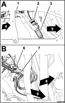
Connect the 3-socket connector of the sonic boom wire harness to the 3-pin connector of the cable for the right ultra-sonic sensor (A of Figure 147).
-
Connect the 3-socket connector of the sonic boom wire harness from the 3-pin connector of the cable for the left ultra-sonic sensor (B of Figure 147).
Assembling the Optional Covered-Boom Kit
Parts needed for this procedure:
| Cover extension assembly (12-nozzle—Toro 120-0621) | 1 |
| Pop rivet (Toro Part No. 114439) | 22 |
| Support bracket (center-section cover—Toro Part No. 131-3703-03) | 4 |
| Clip nut (Toro Part No. 94-2413) | 4 |
| Flange-head bolts (3/8 x 1-1/4 inches—Toro Part No. 110-5050) | 16 |
| Flange locknuts (3/8 inch—Toro Part No. 104-8301) | 16 |
| Cover strap (Toro Part No. 120-0629) | 2 |
| Flange-head bolts (5/16 x 1-1/4 inches—Toro Part No. 323-36) | 4 |
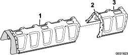
Installing the Cover Extension on to the Center-Section Cover (11-Nozzle)
-
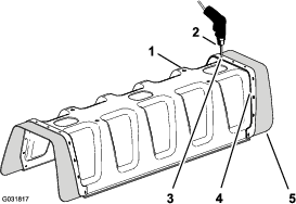
Using a drill with a 5 mm (3/16 inch) drill bit, drill the 11 pop-rivets (Figure 148) that secure the reinforcement plate (with a single row of rivets) and rubber cover to the end of the 11-nozzle section cover for the center-spray section that you removed in step 2 of Removing the Center-Section Cover (11-nozzle) of the Optional Covered-Boom Kit.
-
Remove the reinforcement plate, 11 washers (3/16 inch), and rubber cover from the 11-nozzle boom cover (Figure 148).
Note: Retain the reinforcement plate, washers, and rubber cover for installation in steps 5 and 6.
-
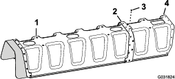
Align the holes in the reinforcement plate (double row)on the cover extension with the holes in the end of the 11-nozzle boom cover (Figure 149).
-
Secure the cover extension to the 11-nozzle section cover (Figure 150) with 11 pop rivets (Toro Part No. 114439).
-
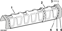
Align the holes in the rubber cover and the reinforcement plate (single row) that you removed in step 2 with the holes in the end of the over extension (Figure 151).
-
Secure the reinforcement plate and rubber cover to the cover extension with the 11 pop rivets (Toro Part No. 114439) and the 11 washers (3/16 inch) that you removed in step 5.
Note: Align the washers (3/16 inch) against the inside surface of the cover extension.
Installing the Support Bracket for the Center-Section Cover
-
Install the 4 clip nuts (Toro Part No. 94-2413) onto the 2 support bracket of the center-section cover (Toro Part No. 131-3703-03) as shown in (Figure 152).
-
At the extension for the center-spray section, locate the 2 pairs of holes in the vertical face of the truss frame with a 25 mm (1 inch) hole spacing (Figure 153).
-
Align the holes in a support bracket (Toro Part No. 131-3703-03) to the holes in the extension for the center-spray section that you identified in step 2 with the wide flange of the bracket to the left; refer to Figure 153.
-
Assemble the support bracket to the truss frame (Figure 153) with 4 flange-head bolts (3/8 x 1-1/4 inches—Toro Part No. 110-5050) and 4 flange locknuts (3/8 inch—Toro Part No. 104-8301).
-
Repeat steps 2 through 4 at the other 2 pairs of holes in the extension for the center-spray section and the other support bracket, flange-head bolts, and flange locknuts.
-
Torque the nuts and bolts to 37 to 45 N∙m (27 to 33 ft-lb).
Installing the Center-Section Cover
-
Align the holes in the center section cover with the holes in the support brackets for the center-section cover (Figure 154).
-
Align the holes in 2 of the cover straps that you removed in step 1 ofRemoving the Center-Section Cover (11-nozzle) of the Optional Covered-Boom Kit with the hose in the cover and 2 of the support brackets (Figure 154).
-
Assemble the cover straps and cover to the support brackets with the 4 flange-head bolts (5/16 x 1-1/4 inches) that you removed in step 1 of Removing the Center-Section Cover (11-nozzle) of the Optional Covered-Boom Kit.
-
Align the holes in the 2 cover straps (Toro Part No. 120-0629) with the 4 remaining holes in the cover and 4 remaining holes in the support brackets (Figure 154).
-
Assemble the cover straps and cover to the support brackets (Figure 154) with the 4 flange-head bolts (5/16 x 1-1/4 inches—Toro Part No. 323-36).
-
Torque the bolts to 1978 to 2542 Ncm (175 to 225 in-lb).
Installing the Navigation Receiver
Parts needed for this procedure:
| Receiver plate | 1 |
| Spacer (3/8 x 1 inch) | 1 |
| Receiver mount | 1 |
| Bolt (3/8 x 3-1/4 inches) | 1 |
| Lock washer (3/8 inch) | 1 |
| Washer (3/8 x 13/16 inch) | 1 |
| Flange locknut (3/8 inch) | 1 |
| Flange-head bolt (5/16 x 3/4 inch) | 1 |
| Flange locknut (5/16 inch) | 1 |
| Flange-head bolt (3/8 x 1-1/2 inches) | 2 |
| Spacer (3/8 x 7/16 inch) | 2 |
| Navigation receiver—X25 GeoLink Precision Spray System Kit, Base, WAAS (Model 41630) | 1 |
| Hex-head bolt (5 x 16 mm) | 3 |
| Washer (5 mm) | 3 |
| Bulkhead adapter (optional CDMA RTK correction modem kit or GSM RTK correction modem kit) | 1 |
| Cellular antenna (optional CDMA RTK correction modem kit or GSM RTK correction modem kit) | 1 |
| Coaxial cable (optional CDMA RTK correction modem kit or GSM RTK correction modem kit) | 1 |
Assembling the Receiver Mount
-
Align the holes in the navigation-receiver plate, spacer (3/8 x 1 inch), and receiver mount (Figure 155).
-
Assemble the receiver plate and spacer to the mount with a bolt (3/8 x 3-1/4 inches), lock washer (3/8 inch), washer (3/8 x 13/16 inch), and flange locknut (3/8 inch) as shown in Figure 155.
-
Assemble the flange-head bolt (5/16 x 3/4 inch) and flange locknut (5/16 inch) through the smaller hole in the receiver mount and the slot in the receiver plate (Figure 155).
-
Tighten the bolts and nuts so that you can rotate the receiver plate with slight resistance.
Installing the Receiver Mount to the Machine
-
Assemble the receiver mount and spacer (3/8 x 7/16 inch) to the roll bar with the flange-head bolt (3/8 x 1-1/2 inches) as shown in Figure 156.
-
Tighten the bolts so that you can rotate the receiver plate with slight resistance.
-
Level the receiver plate left to right (Figure 157).
-
Torque the flange-head bolt (5/16 x 3/4 inch) and flange locknut (5/16 inch) to 1978 to 2542 N∙cm (175 to 225 in-lb).
-
Level the receiver plate front to back (Figure 157).
-
Torque the bolt (3/8 x 3-1/4 inches) and flange locknut (3/8 inch) to 37 to 45 N∙m (27 to 33 ft-lb).
Assembling the Navigation Receiver to the Receiver Plate
-
Align the 3 threaded in the base of the navigation receiver to the 3 holes in the receiver mount (Figure 158).
-
Assemble the receiver to the mount (Figure 158) with the 3 hex-head bolt (5 x 16 mm) and 3 washers (5 mm).
-
Torque the 3 bolts to 576 to 712 N∙cm (51 to 63 in-lb).
Installing the RTK Antenna to the Navigation Receiver
Note: Install the RTK antenna when your machine is equipped with a CDMA RTK or GSM RTK correction modem.
-
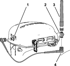
Align the coaxial coupler through the opening in RTK-antenna flange with the bulkhead threads of the coupler down (Figure 159).
Note: Rotate the coaxial coupler as needed to align the flat of the bulkhead threads with the flat at the opening in RTK-antenna flange.
-
Assemble the coaxial coupler to the flange of the receiver plate with the lock washer and jam nut, and tighten the jam nut by hand (Figure 159).
-
Assemble the RTK antenna onto the upper fitting of the coaxial coupler, and tighten the knurl nut of the antenna by hand (Figure 160).
-
Loosely assemble the antenna cable to the lower fitting of the coaxial coupler (Figure 160).
-
Route the cable around the back of the navigation receiver to the coaxial connector of the CDMA or GSM cellular modem (Figure 160).
-
Assemble the antenna cable to coaxial connector of the CDMA or GSM cellular modem (Figure 160).
-
Tighten the knurl nuts of the of the antenna cable by hand.
Installing the Sprayer Monitor
Parts needed for this procedure:
| Monitor mount | 1 |
| Flange-head bolt (6 x 12 mm) | 3 |
| U-bolt (5/16 inch) | 2 |
| Flange locknut (5/16 inch) | 8 |
| Ball mount | 1 |
| Flange-head bolt (5/16 x 3/4 inch) | 4 |
| Monitor—X25 GeoLink Precision Spray System Kit, Base, WAAS (Model 41630) | 1 |
| Monitor Arm—X25 GeoLink Precision Spray System Kit, Base, WAAS (Model 41630) | 1 |
Removing the Steering Wheel
-
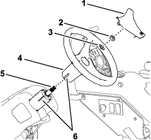
Mark the position of the steering wheel to the steering valve with a piece of tape (Figure 161).
-
Remove the cover from the steering wheel (Figure 161).
-
Remove the nut (5/8 inch) and washer (5/8 inch) that secure the steering wheel to the steering valve, and remove the steering wheel (Figure 161).
Installing the Monitor Mount
-
Align the monitor mount to the machine as shown in Figure 162.
-
Assemble the monitor mount to the housing of the steering valve (Figure 163) with the 3 flange-head bolts (6 x 12 mm).
-
Assemble the plate of the monitor mount to the support tube of the machine chassis (Figure 164) with the 2 U-bolts and 4 flange locknuts (5/16 inch).
-
Torque the 3 flange-head bolts (6 x 12 mm) at the steering valve to 972 to 1198 N∙cm (86 to 106 in-lb); At the support tube, torque the flange locknuts to 1978 to 2542 N∙cm (175 to 225 in-lb).
Installing the Steering Wheel
-
Align the tape mark on the steering wheel to the tale mark on the housing of the steering valve (Figure 165).
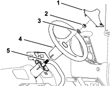
-
Assemble the steering wheel onto the shaft of the steering valve (Figure 165) with the washer (5/8 inch) and nut (5/8 inch) that you removed in step 3 of Removing the Steering Wheel.
-
Torque the nut to 206 to 254 N∙m (152 to 188 ft-lb).
-
Install the cover that you removed in step 2 of Removing the Steering Wheel onto the steering wheel (Figure 171).
Installing the Sprayer Monitor to the Mount
-
Assemble the ball mount to the bracket for the monitor mount (Figure 166) with the 4 flange-head bolt (5/16 x 3/4 inch) and 4 flange locknut (5/16 inch).
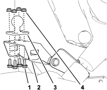
-
Torque the bolts and nuts to 1978 to 2542 N∙cm (175 to 225 in-lb).
-
Assemble the ball fitting of the monitor and the ball mount on the machine to the monitor arm (Figure 167).
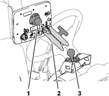
-
Adjust the monitor so that it is viewable from the machine operator’s position and tighten the knob of the monitor arm by hand (Figure 167).
Wiring the Spray Pump Clutch
-
Disconnect the 2-socket connector of the machine wire harness labeled SPRAY PUMP COIL from the 2-pin connector of the alternator (Figure 168).
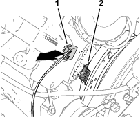
-
Connect the 2-pin connector of the kit wire-harness branch—84 cm (33 inches) labeled PUMP CLUTCH into the 2-socket connector of the machine wire-harness labeled SPRAY PUMP COIL (Figure 169).
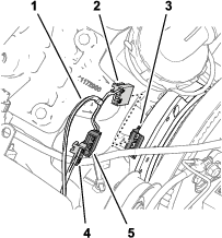
-
Connect the 2-socket connector of the kit wire-harness labeled PUMP CLUTCH into the 2-pin connector of the alternator (Figure 169).
-
Route the wire-harness branch—84 cm (33 inches) against the engine and spray pump so that the harness has clearance from the alternator belt (Figure 170).
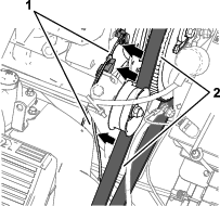
Installing Components for the Sprayer Electrical System
Parts needed for this procedure:
| Battery bracket | 1 |
| Bolt (5/16 x 1-3/4 inches) | 1 |
| Washer (5/16 inch) | 1 |
| Battery (540 A) | 1 |
| Battery retainer | 1 |
| Flange locknut (5/16 inch) | 1 |
| Alternator bracket | 1 |
| Drive pulley 279 mm (11 inch) | 1 |
| Bolt (1/4 x 2-1/4 inches) | 4 |
| Lock washer (1/4 inch) | 4 |
| Alternator (60 A) | 1 |
| Flange-head bolt (8 x 25 mm) | 1 |
| Flange-head bolt (3/8 x 1-1/2 inches) | 1 |
| V-belt | 1 |
Removing the Battery (300 A) and Battery Bracket
-
Remove the 2 flange locknuts and hold-down rod from the 2 J-bolts that secure the battery to the battery bracket of the machine (Figure 171).
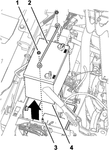
-
Remove the battery from the machine (Figure 171).
Note: You no longer need the flange nuts, hold-down rod, and battery (300 A).
-
Remove the bolts (10-24 x 3/4 inch) and nuts (10-24) that secure the fuse blocks to the battery bracket (Figure 172).
Note: Retain the bolts (10-24 x 3/4 inch) and nuts (10-24) for installation in Installing the Battery Bracket and Battery (540 A).
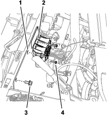
-
Remove the 2 flange-head bolts (3/8 x 3/4 inch) that battery bracket to the shock-support tube of the machine (Figure 172).
Note: Retain the flange-head bolt (3/8 x 3/4 inch) for installation in Installing the Battery Bracket and Battery (540 A).
-
Remove the 2 J-bolts and battery tray from the battery bracket (Figure 173).
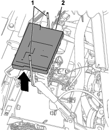
-
Remove the battery bracket from the machine (Figure 174).
Note: You no longer need the J-bolts, battery tray, and battery bracket.
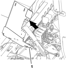
Installing the Battery Bracket and Battery (540 A)
-
Align the new battery bracket to the shock-support tube of the machine and the fuse blocks (Figure 175).
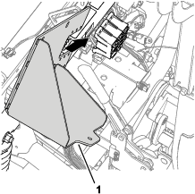
-
Assemble the battery bracket to the shock-support tube (Figure 176) with the 2 flange-head bolt (3/8 x 3/4 inch) that you retainer in step 4 of Removing the Battery (300 A) and Battery Bracket.
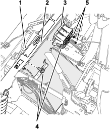
-
Torque the flange head bolts to 37 to 45 N∙m (27 to 33 ft-lb).
-
Secure the fuse blocks to the battery bracket (Figure 176) with the bolt (10–24 x 3/4 inch) and nuts (10-24) that you removed in step 3 of Removing the Battery (300 A) and Battery Bracket.
-
Assemble the battery to the battery bracket with the bolt (5/16 x 1-3/4 inches), washer (5/16 inch), battery retainer, and flange locknut (5/16 inch) as shown in Figure 177.
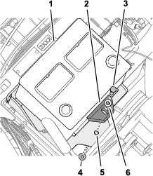
-
Torque the bolt and nut to 1978 to 2542 N∙cm (175 to 225 in-lb).
Installing the Alternator Bracket
-
At the pump head located at 11 o’clock position, loosen the 2 bolts as shown Figure 178 to provide a 7 to 10 mm (1/4 to 3/8 inch) gap between the head of the bolts and the pump.
Note: You do not need to remove the bolts from the spray pump.
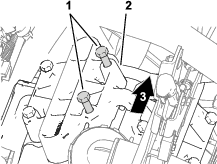
-
Align the alternator bracket between the bolts that you loosened and as shown in step 1 and the pump head Figure 179.
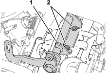
-
Torque the bolts to 61 to 75 N (45 to 55 ft-lb).
Installing the Drive Pulley
-
Loosen the nut for the idler-pulley shaft (Figure 180).
Note: Ensure that there is no belt tension.
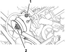
-
Rotate the belt-tension bolt to remove all tension from the sprayer-pump belt (Figure 180).
-
Remove the 4 bolts (1/4 x 1 inch) and 4 lock washers (1/4 inch) that secure the pulley to the sprayer pump (Figure 181).
Important: Do not remove the pulley.
Note: You no longer need the bolts and lock washers.
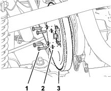
-
Align the holes in the pulley for the alternator (kit) with the holes in the pulley for the sprayer pump (Figure 182).
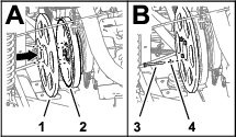
-
Assemble the alternator pulley to the sprayer-pump pulley and sprayer pump with the 4 bolt (1/4 x 2-1/4 inches) and 4 lock washers (1/4 inch).
-
Torque the bolts to 1017 to 1243 N∙m (90 to 110 in-lb).
-
Rotate the belt-tension bolt to increase the tension of the belt until you measure belt 9.5 mm (3/8 inch) of belt deflection when you apply 4.5 kg (10 lb) halfway between the engine and spray pump sprockets.
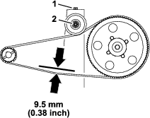
-
Tighten the nut for the idler-pulley shaft to 37 to 44 N∙m (27 to 33 ft-lb).
Installing the Alternator
-
Assemble the alternator (60 A) to the threaded boss of the alternator-bracket (Figure 184) with the flange-head bolt (3/8 x 1-1/2 inches).
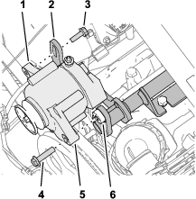
-
Assemble the threaded flange of the alternator to the slotted flange of the alternator bracket (Figure 184) with the flange-head bolt (8 x 25 mm).
-
Assemble the V-belt over the drive pulley 279 mm (11 inch) and the pulley of the alternator (Figure 185).
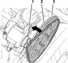
-
Rotate the alternator (Figure 186) up to increase tension on the belt until you measure belt 9.5 mm (3/8 inch) of belt deflection when you apply 4.5 kg (10 lb) halfway between the alternator pulley and drive pulley 279 mm (11 inch).
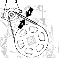
-
Torque the flange-head bolt (8 x 25 mm) to 23 to 29 N∙m (17 to 21 ft-lb).
-
Torque the flange-head bolt (3/8 x 1-1/2 inches) to 37 to 45 N∙m (27 to 33 ft-lb).
Connecting the Kit Wire Harness at the Seat Base
Parts needed for this procedure:
| Relay | 1 |
| Push-in fastener | 1 |
| Fuse (15 A) | 1 |
| Fuse (50 A) | 1 |
Connecting the Alternator (50 A)
-
Connect the 2-socket at the end of the pink wire 57 cm (23-1/2 inches) of the kit wire harness (Figure 187) onto the 2-pin connector of the alternator (50 A).
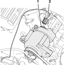
-
Route the pink sense wire away from the alternator belts and secure the wire with a cable tie.
-
Remove the nut from the terminal post (Figure 188) of the alternator (50 A).
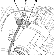
-
Assemble the red, 6 gauge alternator wire onto the terminal post of the alternator (50 A) with the nut (Figure 188).
-
Route the red alternator toward the battery posts and away from the pulley and alternator belt.
-
Torque the nut to 47 to 57 N∙m (34 to 42 ft-lb).
-
Slit the insulator cover over the terminal post of the alternator (Figure 188).
Connecting the ASC 10 Enable Relay
-
Connect the 5-pin connector of the relay into the 5-socket connector (Figure 189) of the kit wire harness labeled ASC 10 ENABLE RELAY.
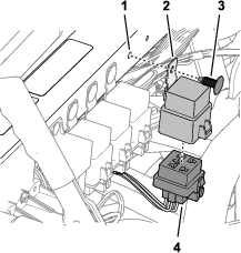
-
Align the hole in the mounting tab of the relay with the hole in the shock-support tube, and secure the relay to the tube with a push-in fastener (Figure 189).
Connecting the Fuse Blocks
-
Set a multi-meter for preforming a continuity test.
-
At fuse block 3 of the machine, insert the multi-meter probe into contact 4 (the right column) of fuse-socket 2 as shown in Figure 190.
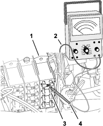
-
At the front side of the fuse blocks, use the other multi-meter probe to identify the blade connector at the end of the red 10-gauge wire that connects to fuse-socket 2—contact 4.
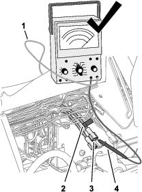
-
Use a piece of tape to mark the connector and wire that you identified in step 3 (Figure 191).
-
Connect the blade connector that you marked in step 4 into the socket connector at the end of the pink wire 51 mm (2 inches) of the kit wire harness (Figure 192).
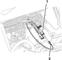
-
Insert the fuse (15 A) into fuse-socket 2 of fuse block 3 until the fuse is fully seated (Figure 193).
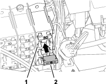
-
Insert the fuse (50 A) into inline-fuse block until the fuse is fully seated (Figure 194).
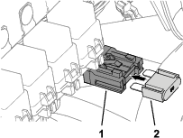
Installing the Wire Harnesses for the Navigation Components
Parts needed for this procedure:
| Data Harness (navigation system)—GeoLink precision-spray-system kit (Model 41630) | 1 |
| Battery Harness (navigation system)—GeoLink precision-spray-system kit (Model 41630) | 1 |
| Cable tie | 8 |
| Quick-connect clamp (red handle) | 1 |
| Quick-connect clamp (black handle) | 1 |
Connecting the Navigation-Data and Electrical Harnesses
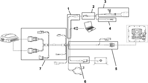
Important: Some connectors of the data harness are not used. Ensure that the caps and plugs of the unused connectors are secure.
Connect the 3-socket connector (electrical-power interface) of the navigation-electrical harness to the 3-pin connector (electrical-power interface) of the data harness (Figure 195).
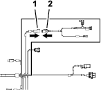
Routing and Connecting the Data Cable to the Navigation Receiver
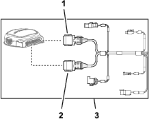
-
Route the 390 cm (153-1/2 inch) branch of the data-harness along the back side of the left, vertical roll-bar tube.
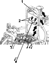
-
Route the 390 cm (153-1/2 inch) branch of the data harness along the right ROPS tube with the 12-socket connector (gray) and 12-socket connector (black) up toward the navigation receiver (Figure 199).
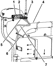
-
Align the 2 keys at the long face of the gray and black 12-socket connector of the data harness with the 2 key slots in the bottom, horizontal wall of the left (gray) 12-pin connector of the navigation receiver (Figure 200).
Note: Use caution when connecting wire harness to the navigation receiver; the alignment keys of the harness connectors are unique to the keyways of the pin connectors of the navigation receiver.
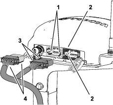
-
Connect the gray and black 12-socket connector of the data harness into the left (gray) 12-pin connector of the navigation receiver until the connector locks snap together securely (Figure 200).
-
Align the 2 keys at the short side of the black 12-socket connector of the data harness with the 2 key slots in the left, vertical wall of the right (black) 12-pin connector of the navigation receiver (Figure 200).
Note: Use caution when connecting wire harness to the navigation receiver; the alignment keys of the harness connectors are unique to the keyways of the pin connectors of the navigation receiver.
-
Connect the black only 12-socket connector of the data harness into the left (black) 12-pin connector of the navigation receiver until the connector locks snap together securely (Figure 200).
-
Secure the 390 cm (153-1/2 inch) branch of the data harness to the right ROPS tube with 2 cable ties as shown in Figure 199.
Note: Ensure that the cable is slack between the 12-socket connectors and the cable tie.
Routing the Navigation-Electrical Harness at the Right Side of the Machine
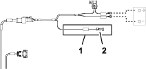
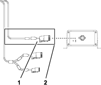
-
Route the data harness and battery harness down the back of the left, vertical roll bar to the cross member for the seat support (Figure 203).
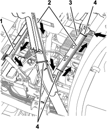
-
Secure the 390 cm (153-1/2 inch) data-harness branch for the navigation receiver to the roll bar as shown in Figure 203.
-
Connect the 1 pin connector of the battery harness labeled ***IMPORTANT*** ONLY CONNECT THIS WIRE TO SWITCHED 12V POWER SOURCE into the 1-socket connector of the 66 cm (26 inch) kit wire-harness branch (Figure 204) labeled (SW’D PWR FOR GEN 2 TOPCON).
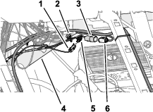
-
Connect the 4-pin connector of the 66 cm (26 inch) kit wire-harness branch labeled ASC 10 PWR & CAN FROM X30 into the 4-socket connector of the data-harness branch labeled CAN 2/ASC10 BUS (Figure 204).
-
Route the data harness and battery harness across the cross member for the seat support and secure the 390 cm (153-1/2 inch) data-harness branch to the cross member with 2 cable ties (Figure 203 and Figure 205).
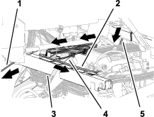
-
Route the 220 cm (86-5/8 inch) battery-harness branch along the right, upper-frame tube (Figure 205).
-
Route the 220 cm (86-5/8 inch) battery-harness branch across the shock-support tube toward the battery (Figure 205).
Note: Ensure that the 100 cm (39-3/8 inch) electrical-interconnect branch (switched power) remains routed against the right, upper-frame tube.
-
Route the 220 cm (86-5/8 inch) data-harness branch (the harness branch with the 26-socket connector) below the control console and forward toward the dash panel (Figure 205).
Routing and Connecting the Data Cable to the Sprayer Monitor
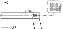
-
Route the 220 cm (86-5/8 inch) data-harness branch (the harness branch with the 26-socket connector) forward and under the dash panel (Figure 207).
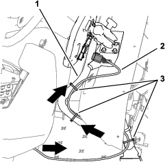
-
Route the 220 cm (86-5/8 inch) data-harness branch along the support tube for the monitor (Figure 207)
-
Align the 26-socket connector of the data harness with the 26-pin connector of the sprayer monitor and press the socket connector into the pin connector until the latch of the connector snaps securely (Figure 208).
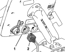
-
Ensure that the 220 cm (86-5/8 inch) data-harness branch has enough slack to allow the sprayer operator to adjust the position of the monitor and secure the harness to the support tube for the monitor with cable ties as shown in Figure 207.
Assembling the Quick-Disconnect Clamps to the Battery
-
Remove the hex nuts and washers from the red and black handle quick-connect clamps (Figure 209).
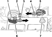
-
Open the latch handle of the quick-connect clamp with the black handle (Figure 210).
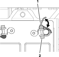
-
Assemble the quick-connect clamp onto the negative battery post, with the threaded post of the clamp aligned toward the center of the battery as shown in Figure 209.
-
Close the latch handle of the quick-connect clamp (Figure 210).
Note: If you need to adjust the clamping force of the quick-connect clamp, open the handle, rotate the knurled nut to increase or decrease the clamping force, and close the handle for the clamp.
-
Repeat steps 2 through 4 for the quick-connect clamp with the red handle at the positive battery post.
Connecting the Battery
Warning
Electrical sparks can cause the battery gasses to explode, resulting in personal injury.
Incorrect battery cable routing could damage the sprayer and cables, causing sparks.
-
Always disconnect the negative (black) battery cable before disconnecting the positive (red) cable.
-
Always connect the positive (red) battery cable before connecting the negative (black) cable.
Battery terminals or metal tools could short against metal sprayer components, causing sparks.
-
When removing or installing the battery, do not allow the battery terminals to touch any metal parts of the sprayer.
-
Do not allow metal tools to short between the battery terminals and metal parts of the sprayer.
-
Always keep the battery strap in place to protect and secure the battery.
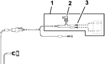
-
Slit the insulator cover of the positive battery cable to the starter as shown in Figure 212.
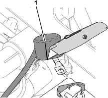
-
Assemble the following wire and cable terminals onto the threaded post of the positive battery terminal (Figure 213) in the following order:
Note: Ensure that the battery-cable terminal (positive) to the engine starter is positioned at the top of the stack of terminals on the threaded post.
-
Ring terminal—22 cm (8-1/2 inch) machine-wire harness labeled BATTERY (+)
-
Ring terminal—220 cm (86-5/8 inch) battery-harness branch labeled ***IMPORTANT*** CONNECT THIS WIRE TO POSITIVE ON BATTERY
-
Ring terminal—60 cm (23-1/2 inch) kit wire-harness branch labeled TO BATTERY POSITIVE
-
Battery-cable terminal (positive)—to the alternator (50 A)
-
Battery-cable terminal (positive)—to the engine starter
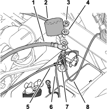
-
-
Assemble the hex nut (1/4 inch) and washer (1/4 inch) onto the threaded post, and torque the nut to 1017 to 1234 N∙cm (90 to 110 in-lb).
-
Align the insulator cover of the positive battery cable to the starter over the threaded post (Figure 213).
-
Assemble the following wire and cable terminals onto the threaded post of the negative battery terminal (Figure 214) in the following order:
Note: Ensure that the battery-cable terminal (negative) to the engine and chassis ground is positioned at the top of the stack of terminals on the threaded post.
-
Ring terminal—220 cm (86-5/8 inch) battery-harness branch labeled (***IMPORTANT*** CONNECT THIS WIRE TO – VE TERMINAL OF BATTERY WHICH IS CONNECTED TO TRACTOR FRAME)
-
Ring terminal—60 cm (23-1/2 inch) kit wire-harness branch—battery negative
-
Battery-cable terminal (negative)—to the engine and chassis ground
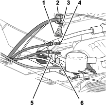
-
Securing the Harness
-
Gather the excess length of the data harness against the right, upper-frame tube (Figure 215).
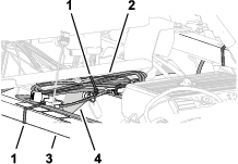
-
Align the data harness to the shock-support tube, and secure the harness to the tube with a cable tie (Figure 215).
-
Align the data-harness bundle to the right, upper-frame tube, and secure the harness bundle to the frame tube with a cable tie (Figure 215).
-
Ensure that there is clearance between the pulleys and belts and the data harness, battery harness, kit wire harness, and battery cables.
Secure the wire harness and cables with cable ties as needed to provide clearance away from the belts and pulleys.
Installing the Hood and the Left and Right Front Fenders
Parts needed for this procedure:
| Push-in fastener | 13 |
Installing the Hood
-
Align the hood holes in the hood with the holes in the dash panel and frame of the machine (Figure 216).
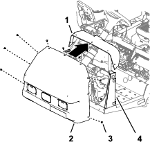
-
Secure the hood to the dash and frame with 9 push-in fastener (Figure 216).
-
Connect the 2 electrical connectors (2-socket) of the machine wire harness from the 2-pin connectors of the left and right headlights (Figure 217).
Installing the Left and Right Front Fenders
-
Align the inner-fender shroud to the left, upper- and left, lower-frame tubes (Figure 217).
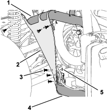
-
Secure the inner-fender shroud to the frame tubes with the 6 push-in fasteners (Figure 218).
-
Align the holes in the fender with the holes in the frame of the machine as shown in Figure 218.
-
Loosely assemble the fender to the frame (Figure 219) with the 3 bolt (5/16 x 1 inch) and 3 washer (5/16 inch) that you removed in step 2 of Removing the Left and Right Front Fenders.
-
Secure the fender to the frame channel with the 2 push-in fasteners (Figure 220).
-
Torque the bolt (5/16 x 1 inch) to 1978 to 2542 N∙cm (175 to 225 in-lb).
-
Repeat steps 1 through 6 for the inner-fender shroud and fender at the other side of the machine.
Installing the Engine-Access Panel and the Seat
Installing the Engine-Access Panel
-
Align the latches of the engine access panel with the bushings in the panel-support brackets on the roll bar (Figure 221).
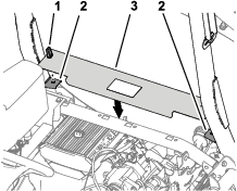
-
Assemble the panel onto the brackets (Figure 221).
-
Rotate the handles latches down to secure the panel to the brackets (Figure 221).
Installing the Seat
-
Align the seat and seat plate to the chassis of the machine (Figure 222).
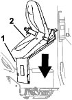
-
Align the holes in the pivot fittings of the seat pan with the holes in the chassis bracket (Figure 223).
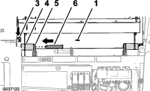
-
Assemble the seat pan to the chassis brackets with the 2 pivot pins (Figure 223).
-
Secure the pivot pins to the machine with the 2 hairpins (Figure 223).
-
Assemble the prop rod to the bracket of the seat with the washer and hairpin (Figure 224).
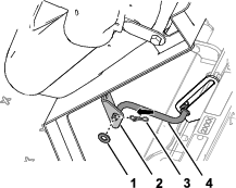
-
Plug the 2-socket connector of the machine wire harness into the connector for the seat switch until the connectors latch securely (Figure 225).
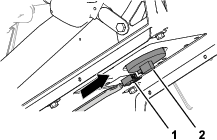
-
Rotate the seat forward slightly, remove the prop rod from the detent, rotate the seat down until the seat latches securely.
Programming the Machine Settings
-
Insert the key into the key switch and rotate it to the ON position.
The splash screen appears in the InfoCenter display and the indicator light illuminates briefly (Figure 226).
Note: Do not start the engine.
-
At the Home screen, press the center button on the InfoCenter to access the navigation screen (Figure 227).
-
Press the center button on the InfoCenter to access the Main Menu (Figure 227).
-
At the MAIN MENU screen, press the center button to navigate to the SETTING option, and press the right button to select the option (Figure 228).
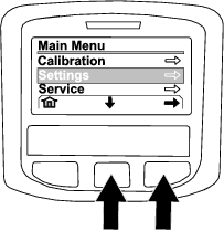
-
At the SETTING screen, press the center button to navigate to the PROTECTED SETTINGS option, and press the right button to select the option.
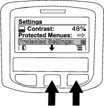
-
Enter the PIN code as follows:
-
Press the center button as needed to enter the PIN code number for the left position (Figure 230).
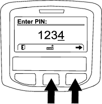
-
Press the right button to navigate to the next PIN code number position (Figure 230).
-
Repeat steps 1 and 2 for the 3 other PIN code number positions.
-
When all the PIN code numbers are entered press the right button (Figure 230) and then press the center button to enter the PIN code (Figure 231).
The indicator light illuminates briefly.
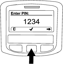
-
-
Press the center button to navigate to the GEOLINK option, and press the right button to set the option (Figure 232).
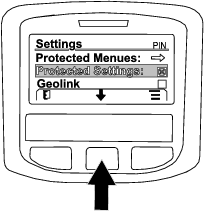
The GeoLink confirmation screen displays in the InfoCenter (Figure 233).

-
Rotate the ignition switch to the OFF position and then to the ON position.
-
The GEOLINK splash screen initially appears when you rotate the key switch to the ON position.