| Maintenance Service Interval | Maintenance Procedure |
|---|---|
| Before each use or daily |
|
Introduction
This machine is mounted to a Workman Utility Vehicle and is intended to be used by professional, hired operators in commercial applications. It is primarily designed for metering and dispersing materials, under a range of moisture conditions, without clogging or drastically affecting the dispersion.
Read this information carefully to learn how to operate and maintain your product properly and to avoid injury and product damage. You are responsible for operating the product properly and safely.
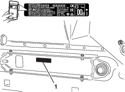
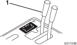
Whenever you need service, genuine Toro parts, or additional information, contact an Authorized Service Dealer or Toro Customer Service and have the model and serial numbers of your product ready. Figure 1 identifies the location of the model and serial numbers on the product. Write the numbers in the space provided.
Important: With your mobile device, you can scan the QR code (if equipped) on the serial number plate to access warranty, parts, and other product information.
This manual identifies potential hazards and has safety messages identified by the safety-alert symbol (Figure 2), which signals a hazard that may cause serious injury or death if you do not follow the recommended precautions.

This manual uses 2 words to highlight information. Important calls attention to special mechanical information and Note emphasizes general information worthy of special attention.
This product complies with all relevant European directives, for details please see the separate product specific Declaration of Conformity (DOC) sheet.
Warning
CALIFORNIA
Proposition 65 Warning
Use of this product may cause exposure to chemicals known to the State of California to cause cancer, birth defects, or other reproductive harm.
Safety
General Safety
This product is capable of causing personal injury. Always follow all safety instructions to avoid serious personal injury.
Using this product for purposes other than its intended use could prove dangerous to you and bystanders.
-
Read and understand the contents of both this Operator’s Manual and the operator’s manual of the vehicle before using this machine. Ensure that everyone using this product knows how to use this machine and the vehicle and understands the warnings.
-
Use your full attention while operating the machine. Do not engage in any activity that causes distractions; otherwise, injury or property damage may occur.
-
Do not put your hands or feet near moving components of the machine.
-
Do not operate the machine without all guards and other safety protective devices in place and working on the machine.
-
Keep the machine a safe distance away from bystanders while it is moving.
-
Keep children out of the operating area. Never allow children to operate the machine.
-
Stop the machine, shut off the engine, engage the parking brake, remove the key, and wait for all moving parts to stop before servicing, fueling, or unclogging the machine.
Improperly using or maintaining this machine can result in injury.
To reduce the potential for injury, comply with these safety instructions
and always pay attention to the safety-alert symbol  , which means Caution, Warning,
or Danger—personal safety instruction. Failure to comply with
these instructions may result in personal injury or death.
, which means Caution, Warning,
or Danger—personal safety instruction. Failure to comply with
these instructions may result in personal injury or death.
You can find additional safety information where needed throughout this manual.
Safety and Instructional Decals
 |
Safety decals and instructions are easily visible to the operator and are located near any area of potential danger. Replace any decal that is damaged or missing. |


Setup
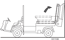
Removing the 2/3 or Full Bed
Note: If the Workman is equipped with a H.D. Hitch Frame it does not have to be removed from the vehicle but the weight of the hitch frame must be subtracted from the payload capacity of the hopper. Refer to the Workman Operating Instructions.
-
Park the vehicle on a level surface.
-
Start the engine. Engage the hydraulic lift lever and lower the bed until the cylinders are loose in the slots.
-
Release the lift lever. Shut off the engine and remove the key.
-
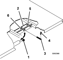
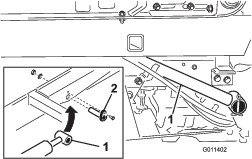
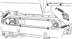
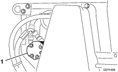
Remove the lynch pins from the outer ends of the cylinder rod clevis pins (Figure 3).
-
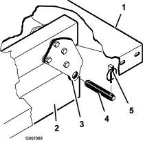
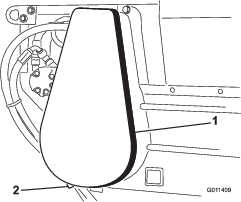
Remove the clevis pins securing the cylinder rod ends to the bed mounting plates by pushing the pins towards the inside (Figure 4).
-
Remove the lynch pins and clevis pins securing the pivot brackets to the frame channels (Figure 4).
-
Lift the bed off of the vehicle.
Caution
The full bed weighs approximately 148 kg (325 lb), so do not try to install or remove it by yourself.
Use an overhead hoist or get the help of 2 or 3 other people.
-
Store the cylinders in the storage clips. Engage the hydraulic lift lock lever on the vehicle to prevent accidental extension of the lift cylinders.
Mounting the Topdresser
Parts needed for this procedure:
| Attachment bracket | 2 |
| Clevis pin | 2 |
| Lynch pin | 4 |
| Cap screw (1/2 x 1 inch) | 4 |
| Flat washer | 8 |
| Locknut (1/2 inch) | 4 |
| Spacer mount | 2 |
Note: On vehicles with serial numbers prior to 239999999, the Remote Hydraulic Control Kit (Model 07415) must be installed on the Workman before installation of the TopDresser 1800.
Note: An Engine Cover Kit, Part No. 99-1214 for Liquid Cooled Gas Workman or Part No. 92-5963 for Diesel Workman, must be installed on the Workman to prevent material from overflowing directly onto the engine.
-
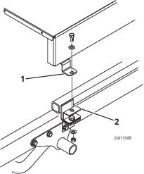
Remove 2 flange-head cap screws and flange locknuts securing rear of each engine frame mounting bracket to each side of vehicle frame (Figure 5).
Note: If the Workman is equipped with a H.D. Hitch Frame, the attachment mount brackets (Steps 1 and 2) will already be mounted on Workman. Proceed to step 3.
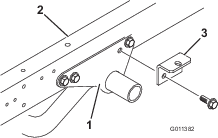
-
Loosely secure a attachment bracket to each engine frame mounting bracket and vehicle frame with (2) flange-head cap screws and flange locknuts previously removed (Figure 5).
Note: If the Workman is equipped with a H.D. Hitch Frame, install the spacer mounts, steps 3 and 4, otherwise proceed to step 5.
-
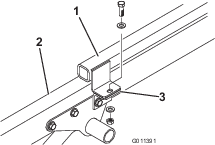
Remove the cap screw, 2 flat washers, and locknut securing each attachment bracket to hitch frame tabs (Figure 6).
-
Secure a spacer mount to top of each hitch frame tab with the cap screw, 2 flat washers, and locknut previously removed (Figure 7).
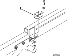
-
Position the machine onto the vehicle frame, aligning the holes in the rear mounting brackets with the holes in each side of the frame (Figure 7).
Note: When using a forklift to lift the topdresser, insert the forks through the holes in the rear flap and into the channels.
Note: If you are using the optional Lift Assembly Kit (92-4452) to lift the topdresser, proceed as follows:
-
Place the lift bracket on top of hopper.
-
Attach the chains to lift eyes on each corner of hopper.
Important: When removing the TopDresser, always remove the mounting bolts and pins before lifting.
-
-
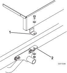
Secure each rear mounting bracket to the vehicle frame with a clevis pin and 2 lynch pins (Figure 8).

-
Loosely secure the top of each attachment bracket (Figure 9) or spacer mount (Figure 10) to the mounting tab on each side of the topdresser with a 1/2 x 1 inch cap screw, 2 flat washers, and locknuts. Tighten all fasteners.
Connecting the Lift Cylinders
Parts needed for this procedure:
| Cylinder pin | 2 |
| Cap screw (1/4 x 3/4 inch) | 2 |
| Locknut (1/4 inch) | 2 |
-
Secure each lift cylinder rod end to topdresser base with a cylinder pin (Figure 11).
-
Secure each cylinder pin to the topdresser base with a cap screw (1/4 x 3/4 inch), a flat washer, and a nut (Figure 11).
Important: Always unlock the dump stop lever before attempting to attach the cylinder for tilting. Use the tilt of the cylinders only for service of the engine or hydraulics underneath.
Warning
Failure to properly support the topdresser when performing service could result in serious personal injury.
Do not rely on the cylinders to hold up the machine. Block the topdresser up before going underneath to perform any type of service.
Important: On vehicles with serial numbers 240000001 and up, the bed or topdresser cannot be raised unless the lift cylinder hoses are connected to the vehicle.
Caution
Failure to follow the proper procedures for tilting the hopper of the topdresser could cause serious injury.
Remove the front mounting bolts before tilting the hopper.
Tilt the hopper only when the hopper is empty.
Using the Bed Support
Parts needed for this procedure:
| Bed support (supplied with Workman vehicle) | – |
Important: Always install or remove the bed support from the outside of the bed.
-
Raise the bed until the lift cylinders are fully extended.
-
Remove the bed support from the storage brackets on the back of the ROPS panel (Figure 12).
-
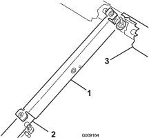
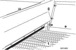
Push the bed support onto the cylinder rod, and ensure that the support end tabs rest on the end of the cylinder barrel and cylinder-rod end (Figure 13).
-
When you are finished, remove the bed support from the cylinder, and insert it into the brackets on the back of the ROPS panel.
Important: Do not try to lower the bed with the bed support on the cylinder.
Connecting the Hydraulic Couplers
-
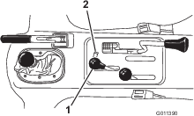
On vehicles with serial numbers prior to 239999999, move the remote hydraulic valve handle (Figure 14) to the float position and on vehicles with serial numbers 240000001 and up, move the hydraulic lift lever (Figure 15) back and forth to remove the system pressure and ease the disconnection of the quick couplers.
-
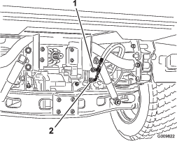
On vehicles with serial numbers 240000001 and up, disconnect the 2 lift cylinder hoses from the hoses secured to the coupler bracket (Figure 16). Insert the caps into the cylinder hose quick couplers.
-
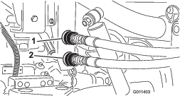
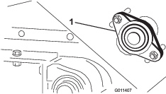
Clean any dirt from the topdresser quick couplers (Figure 17) before connecting them. Dirty couplers can introduce contamination to the system. After cleaning, attach both quick couplers to the Workman. The hoses are marked “A” and “B”, match them to the quick couplers when installing. Ensure that both quick couplers are full engaged.
Note: The couplers shown in Figure 17 are from vehicles with serial numbers prior to 239999999.
Important: The Workman hydraulic system operates on Dexron III automatic transmission fluid. This fluid provides gear and bearing lubrication as well as fluid for operating the hydraulic system.When the remote hydraulic system quick couplers are connected, hydraulic fluid flows from the machine to the vehicle. If the hydraulic fluid in the machine is not the same or equivalent to the fluid in the vehicle, component damage to the transaxle or hydraulic system may result.Check for fluid compatibility and take appropriate action if the machine is subsequently used in conjunction with any other product using fluids other than Dexron III ATF.
Warning
Hydraulic fluid escaping under pressure can penetrate skin and cause injury.
-
Seek immediate medical attention if fluid is injected into skin. Injected fluid must be surgically removed within a few hours by a doctor.
-
Ensure that all hydraulic-fluid hoses and lines are in good condition and all hydraulic connections and fittings are tight before applying pressure to the hydraulic system.
-
Keep your body and hands away from pin-hole leaks or nozzles that eject high-pressure hydraulic fluid.
-
Use cardboard or paper to find hydraulic leaks.
-
Safely relieve all pressure in the hydraulic system before performing any work on the hydraulic system.
Important: Check the hydraulic fluid level after installation of the topdresser. Check the operation of the topdresser, then check the level of the hydraulic fluid again. Operation of a vehicle with low fluid level can damage the pump, remote hydraulics, power steering, and vehicle transaxle. Use Dexron III automatic transmission fluid if additional fluid is needed.
-
-
Start the vehicle engine and test the rotation of the conveyor and the brush. Place the remote hydraulics lever of the vehicle in the RUN position. The rotation should be as shown in Figure 18. If the rotation is backwards the quick couplers need to be reversed.

Important: Ensure that the hoses are routed away from any moving, sharp, or hot components.
-
Visually inspect the hydraulic system for leaks, loose fasteners, missing parts, and improperly routed lines. Make all repairs before operating.
Product Overview
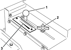
Gate Metering Control
The black knobs on the left rear side of the machine are used to adjust and lock the gate into the desired open height position.
Rate Scale
Use the rate scale (Figure 19) to determine the desired flow rate. Refer to Sand Application Rate.
Note: Specifications and design are subject to change without notice.
Dimensions and Weights
| Length | 137 cm (54 inches) |
| Width | 185 cm (73 inches) |
| Spreading width | 152 cm (60 inches) |
| Inside clear width | 175 cm (69 inches) |
| Height, mounted on Workman vehicle | 126 cm (49.5 inches) |
| Shipping weight | 386 kg (850 pounds) |
| Dry weight | 367 kg (808 pounds) |
| Hopper capacity | 0.5 cubic meters (18 cu ft) |
Required Attachments
| Remote Hydraulic Control Kit (For vehicles with serial numbers prior to 239999999) | Model No. 07415 |
| Engine Cover Kit (Mitsubishi, liquid-cooled diesel Workman) or | Part No. 92-5963 |
| Engine Cover Kit (Mitsubishi, liquid-cooled gas Workman)or | Part No. 99-1214 |
| Engine Cover Kit (Daihatsu, liquid-cooled gas and diesel Workman)and | Part No. 117-4867 (Included on HD series models) |
| 1/3 Area Cover (Daihatsu, liquid-cooled gas and diesel Workman) Note: The 1/3 cover will not fit if a High Air Intake Kit is installed. A 1/3 Flat Bed must be used if a High Air Intake Kit is installed. or | Part No. 93-9225 |
| 1/3 Flat Bed | Model No. 07341 |
Recommended Accessories
| Jack Stand Assembly (Qty. 4)Requires: Hitch Pin (Qty. 4) | Part No. 105-9482-03Part No. 100-4523 |
| Tachometer/Speedometer Kit (Mitsubishi, liquid-cooled gas Workman) | Part No. 87-9950 |
| Tachometer/Speedometer Kit (Mitsubishi, liquid-cooled diesel Workman) | Part No. 87-9970 |
| Tachometer/Speedometer Kit (air-cooled gas Workman 3000–4000) | Part No. 87-9960 |
| Tachometer/Speedometer Kit (air-cooled gas Workman HD) | Part No. 115-7786 |
| Tachometer/Speedometer Kit (Daihatsu, liquid-cooled gas Workman 3000–4000) | Part No. 105-9498 |
| Tachometer/Speedometer Kit (Daihatsu, liquid-cooled diesel Workman 3000–4000) | Part No. 105-9499 |
| Tachometer Kit (air-cooled gas Workman 3000–4000) | Part No. 107-7977 |
| Tachometer Kit (Daihatsu, liquid-cooled gas Workman 3000–4000) | Part No. 107-7975 |
| Tachometer Kit (Daihatsu, liquid-cooled diesel Workman 3000–4000) | Part No. 107-7976 |
| Hand Throttle Kit (for vehicles with serial numbers 240000001 and up) | Model 07420 |
| Hand Throttle Kit (for vehicles with serial numbers prior to 239999999) | Model 07416 |
Attachments/Accessories
A selection of Toro approved attachments and accessories is available for use with the machine to enhance and expand its capabilities. Contact your Authorized Service Dealer or authorized Toro distributor or go to www.Toro.com for a list of all approved attachments and accessories.
To ensure optimum performance and continued safety certification of the machine, use only genuine Toro replacement parts and accessories. Replacement parts and accessories made by other manufacturers could be dangerous, and such use could void the product warranty.
Operation
Note: Determine the left and right sides of the machine from the normal operating position.
Before Operation
Before Operation Safety
-
The machine has different balance, weight, and handling characteristics compared to some other types of equipment. Read and understand the contents of this Operator's Manual before operating the machine. Become familiar with all controls and know how to stop quickly.
-
Never allow children or untrained people to operate or service the machine. Local regulations may restrict the age of the operator. The owner is responsible for training all operators and mechanics.
-
Become familiar with the safe operation of the equipment, operator controls, and safety signs.
-
Know how to stop the machine and shut off the engine quickly.
-
Check that operator-presence controls, safety switches, and shields are attached and functioning properly. Do not operate the machine unless they are functioning properly.
-
Keep all shields and safety devices in place. If a shield, safety device, or decal is illegible or missing, repair or replace it before operating the machine.
Note: The front 1/3 area of the Workman cargo zone must be covered by a 1/3 attachment or shield when using the topdresser.
-
Tighten any loose nuts, bolts, and screws to ensure that the machine is in safe operating condition. Ensure that the machine components are in place and secure.
-
Ensure that your vehicle is suitable for use with an implement of this weight by checking with your vehicle supplier or manufacturer.
-
Park the vehicle on a level surface, engage the parking brake, shut off the engine, remove the key, and wait for all movement to stop before leaving the vehicle and the topdresser.
During Operation
During Operation Safety
-
The owner/operator can prevent and is responsible for accidents that may cause personal injury or property damage.
-
Wear appropriate clothing, including eye protection; long pants; substantial, slip-resistant footwear; and hearing protection. Tie back long hair, secure loose clothing, and do not wear loose jewelry.
-
Use your full attention while operating the machine. Do not engage in any activity that causes distractions; otherwise, injury or property damage may occur.
-
Use your full attention while operating the machine. Do not engage in any activity that causes distractions; otherwise, injury or property damage may occur.
-
Do not operate the machine when tired, ill, or under the influence of alcohol or drugs.
-
Ensure that there are not more occupants (you and your passenger(s)) than the number of handholds equipped on the machine.
-
Keep your hands and feet out of the hopper.
-
Remain seated whenever the vehicle is in motion.
-
Using the machine demands attention. Failing to operate the vehicle safely may result in an accident, tip-over of the vehicle, and serious injury or death. Drive carefully, and to prevent tipping or loss of control, do the following:
-
Use extreme caution, reduce the speed, and maintain a safe distance around sand traps, ditches, water hazards, ramps, unfamiliar areas, or other hazards.
-
Reduce the speed of a loaded machine when negotiating terrain undulations to avoid causing the machine to become unstable.
-
Watch for holes or other hidden hazards.
-
Use caution when operating on a steep slope. Travel straight up and down slopes. Reduce speed when making sharp turns or when turning on hillsides. Avoid turning on hillsides whenever possible.
-
Use extra caution when operating on wet surfaces, at higher speeds or with a full load. Stopping time increases with a full load. Shift into a lower gear before starting up or down a hill.
-
Avoid sudden stops and starts. Do not go from reverse to forward or forward to reverse without coming to a complete stop.
-
Do not attempt sharp turns or abrupt maneuvers or other unsafe driving actions that may cause a loss of control.
-
Be aware of your surroundings when turning or backing up the machine. Ensure that the area is clear and keep all bystanders at a safe distance. Proceed slowly.
-
Watch out for traffic when near or crossing roads. Always yield the right of way to pedestrians and other vehicles. Obey all traffic rules and check for local regulations on the operation of the machine on or near highways.
-
Always watch out for and avoid low overhangs such as tree limbs, door jambs, overhead walkways, etc. Ensure that there is enough room over head to easily clear the vehicle and your head.
-
Do not operate the machine when there is the risk of lightning.
-
If you are ever unsure about safe operation, stop working and ask your supervisor.
-
Do not leave the machine unattended while the vehicle is running.
-
-
Do not carry loads that exceed the load limits of the vehicle.
-
The stability of loads can vary—for example, high loads have a higher center of gravity. Reduce the maximum load limits to ensure better stability, if necessary.
-
To avoid causing the machine to tip over, do the following:
-
Carefully monitor the height and weight of the load. Higher and heavier loads can increase the risk of tipping.
-
Distribute the load evenly, from front to back and side to side.
-
Be careful when turning and avoid unsafe maneuvers.
-
Always ensure that the machine is connected to the vehicle before loading.
-
Do not put large or heavy objects into the hopper. This could damage the belt and rollers. Also ensure that the load has a uniform texture. The machine can unpredictably throw small rocks in the sand.
-
-
Do not stand behind the machine when unloading.
-
Unload the topdresser or disconnect it from the vehicle only while on a level surface.
-
Do not travel with the topdresser in the fully raised position. This increases the risk of tipping over the vehicle.
-
Travel with the machine in the lowered position.
-
Shut off the attachment when approaching people, vehicles, vehicle crossings, or pedestrian crossings.
Slope Safety
-
Review the vehicle specifications to ensure that you do not exceed its slope capabilities.
-
Slopes are a major factor related to loss of control and rollover accidents, which can result in severe injury or death. The operator is responsible for safe slope operation. Operating the machine on any slope requires extra caution.
-
The operator must evaluate the site conditions to determine if the slope is safe for machine operation including surveying the site. Always use common sense and good judgment when performing this survey.
-
The operator must review the slope instructions listed below for operating the machine on slopes. Consider the operating conditions on that day to determine whether to use the machine at the site. Changes in the terrain can result in a change in slope operation for the machine.
-
Avoid starting, stopping, or turning the machine on slopes. Avoid making sudden changes in speed or direction. Make turns slowly and gradually.
-
Do not operate a machine under any conditions where traction, steering, or stability is in question.
-
Remove or mark obstructions such as ditches, holes, ruts, bumps, rocks, or other hidden hazards. Tall grass can hide obstructions. Uneven terrain could overturn the machine.
-
Be aware that operating the machine on wet grass, across slopes, or downhill may cause the machine to lose traction. Loss of traction to the drive wheels may result in sliding and a loss of braking and steering.
-
Use extreme caution when operating the machine near drop offs, ditches, embankments, water hazards, or other hazards. The machine could suddenly roll over if a wheel goes over the edge or the edge caves in. Establish a safety area between the machine and any hazard.
Checking the Safety-Interlock System
The purpose of the safety-interlock system is to prevent the engine from cranking or starting, unless you press the clutch pedal.
Caution
If the safety-interlock switches are disconnected or damaged, the machine could operate unexpectedly, causing personal injury.
-
Do not tamper with the safety-interlock switches.
-
Check the operation of the safety-interlock switches daily, and replace any damaged switches before operating the machine.
Note: Refer to the attachment Operator’s Manual for procedures on checking the attachment interlock system.
Verifying the Clutch-Interlock Switch
-
Sit on the operator’s seat and engage the parking brake.
-
Move the shift lever to the NEUTRAL position.
Note: The engine does not start if the hydraulic-lift lever is locked in the forward position.
-
Without pressing the clutch pedal, rotate the key switch clockwise to the START position.
Note: If the engine cranks or starts, there is a malfunction in the interlock system that you must repair before operating the machine.
Verifying the Hydraulic-Lift Lever Safety-Interlock Switch
-
Sit on the operator’s seat and engage the parking brake.
-
Move the shift lever to the NEUTRAL position and ensure that the hydraulic-lift lever is in the center position.
-
Press the clutch pedal.
-
Move the hydraulic-lift lever forward and rotate the key switch to the START position.
Note: If the engine cranks or starts, there is a malfunction in the interlock system that you must repair before operating the machine.
Operating the Machine
-
Sit on the seat and engage the parking brake.
-
Disengage the PTO (if so equipped) and return hand throttle lever to OFF position (if so equipped).
-
Place the Workman Remote Hydraulic Valve Handle in the OFF position.
-
Move the shift lever to NEUTRAL position and press the clutch lever.
-
Insert the key and rotate it clockwise to start the engine. Release the key when the engine starts.
-
Practice starting, driving, and stopping the Workman vehicle. Always read and understand the Operator's Manual for the Workman vehicle before using this machine.
-
Check for smooth operation of belt before adding material in the hopper.
-
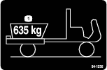
Place sand or other topdressing material in the hopper. The maximum volume of material that can be put into the hopper is 0.5 cubic meters (18 cu ft). Generally, sand weighs 1.6 kg/L (100 lb / cu ft) and could overload the Workman vehicle if more than 635 to 680 kg (1400 to 1500 lb) are loaded into the hopper.
Important: When any other attachments, such as the H.D. Hitch frame, are installed on the Workman while using the topdresser, the weight of those attachments must be subtracted from the payload capacity of the hopper.
A method for determining the total weight of your attachments would be to place the rear tires on a scale. The maximum weight capacity of the rear axle of the Workman 3000/4000 Series is 1179 kg (2600 lb) and 1372 kg (3025 lb) for the Workman HD Series.
Danger
Heavy loads increase stopping distance and reduce your ability to turn quickly without tipping over.
Transporting or topdressing with a full load can cause shifting of the sand. This shifting happens most often while turning, going up or down hills, suddenly changing speeds or while driving over rough surfaces. Shifting loads can lead to tipovers.
Use caution when transporting or topdressing with a full load.
As a general rule, position the weight of the load evenly from front to rear and evenly from side to side.
Never tilt the topdresser bed for maintenance with any material in the hopper. Tilt the topdresser bed only when the hopper is empty.
-
Transport to the area to be topdressed.
-
Adjust the metering gate to the desired rate. Lock into position with the black knob.
-
Move the shift lever into LO range position. Select the desired forward speed and begin moving. Refer to Sand Application Rate.
-
On vehicles with serial numbers prior to 239999999, pull the remote hydraulic lever back to the RUN position. On vehicles with serial numbers 240000001 and up, lock the hydraulic lift lever in the forward position; the machine is now topdressing.
Sand Application Rate
The rate of sand applied depends on the gate setting and the gear/range setting. Sand varies in moisture and coarseness (size of grain) which affects the rate. Take these factors into consideration when deciding the amount of sand required for the application. Test a small area to decide the correct amount. To increase the application rate, either open the gate to a higher scale mark or shift the Workman vehicle to a lower gear.
Note: On vehicles with serial numbers 240000001 and up, the sand application rate will decrease when you turn the vehicle. Avoid making sharp turns when topdressing.
To ensure consistent application, from green to green, it is highly recommended to use a tachometer and/or hand throttle to maintain constant engine speed while topdressing.
Warning
Tipping or rolling the vehicle on a hill will cause serious injury.
If the engine stalls or you lose headway on a hill, never attempt to turn the vehicle around.
Always back straight down a hill in reverse gear.
Do not back down in neutral or with the clutch pressed, using only the brakes.
Never add sideboards or panels to the top of the hopper to increase the load capacity. The additional weight will cause tipping or rolling of the vehicle and lead to serious injury.
Do not drive across a hill: drive up and down the hill. Avoid turning on a hill. Do not accelerate or decelerate fast. A sudden change in speed can initiate a tipover.
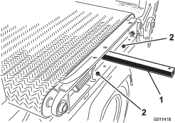
Sand Precautions
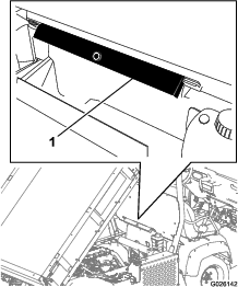
The TopDresser 1800 is equipped with a flexible gate edge (Figure 20) and spring release mechanism to reduce the chance of sand chunks or rocks getting lodged during operation. To ensure long belt life, sift or check the sand for rocks with sharp edges that may damage the conveyor belt.
Operating the Machine in Cold Weather
You can use the machine in cold weather, with certain limitations, to apply a salt/sand mixture on pavement for ice control. The PVC conveyor belt material becomes very stiff in cold weather and requires more power to operate. The life of the belt is reduced by approximately 50% when operated below temperatures of 5 degrees C (40 degrees F). Under no conditions should the topdresser be operated below temperatures of -7 degrees C (20 degrees F).
-
Increase the belt tension by adjusting the spring compression to 101 mm (4 inches). Refer to Adjusting the Conveyor Belt.
-
Always run the belt before adding material, to ensure that no moisture has frozen the belt system. Damage to the belt or roller may occur if slippage occurs between the belt and the drive roller.
Important: Set the belt tension to the normal 112 mm (4-7/16 inches) spring compression adjustment before operating the machine under normal temperature conditions.
After Operation
After Operation Safety
-
Park the machine on a firm, level surface.
-
Always shut off the engine, remove the key (if equipped), wait for all moving parts to stop, and allow the machine to cool before adjusting, servicing, cleaning, or storing the machine.
-
Ensure that the hopper is in the down position.
-
Keep all parts of the machine in good working condition and all hardware tightened.
-
Replace all worn, damaged, or missing decals.
Maintenance
Note: Determine the left and right sides of the machine from the normal operating position.
Note: Download a free copy of the electrical or hydraulic schematic by visiting www.Toro.com and searching for your machine from the Manuals link on the home page.
Recommended Maintenance Schedule(s)
| Maintenance Service Interval | Maintenance Procedure |
|---|---|
| Before each use or daily |
|
| Every 25 hours |
|
Maintenance Safety
-
Before servicing or adjusting the machine, stop the machine, shut off the engine, engage the parking brake, remove the key, and wait for all moving parts to stop.
-
Perform only those maintenance instructions described in this manual. If major repairs are ever needed or assistance is desired, contact an authorized Toro distributor.
-
Ensure that the machine is in safe operating condition by keeping nuts, bolts, and screws tight.
-
If possible, do not perform maintenance while the engine is running. Keep away from moving parts.
-
Do not check or adjust the chain tension when the vehicle engine is running.
-
Carefully release pressure from components with stored energy.
-
Support the machine with blocks or storage stands when working beneath it. Never rely on the hydraulics on the vehicle to support the machine.
-
After maintaining or adjusting the machine, ensure that all guards are installed.
Lubrication
| Maintenance Service Interval | Maintenance Procedure |
|---|---|
| Every 25 hours |
|
The machine has 5 grease fittings that must be lubricated with a No. 2 lithium grease.
The grease fitting locations (Figure 21) and quantities are: Roller shaft bearings (4) and Brush shaft bearing (1).
Important: Lubricate the bearings to maintain a slight leakage between bearings and housings. Too much grease can cause overheating.
Note: We do not recommend lubricating the drive chain unless it becomes stiff because of rust. If the chain rusts, you can lubricate it lightly with a dry-type lubricant.
Hydraulic System Safety
-
Seek immediate medical attention if fluid is injected into skin. Injected fluid must be surgically removed within a few hours by a doctor.
-
Ensure that all hydraulic-fluid hoses and lines are in good condition and all hydraulic connections and fittings are tight before applying pressure to the hydraulic system.
-
Keep your body and hands away from pinhole leaks or nozzles that eject high-pressure hydraulic fluid.
-
Use cardboard or paper to find hydraulic leaks.
-
Safely relieve all pressure in the hydraulic system before performing any work on the hydraulic system.
Checking the Hydraulic Lines and Hoses
| Maintenance Service Interval | Maintenance Procedure |
|---|---|
| Before each use or daily |
|
Check the hydraulic lines and hoses for leaks, kinked lines, loose mounting supports, wear, loose fittings, weather deterioration, and chemical deterioration. Make all necessary repairs before operating.
Adjusting the Brush
The brush must make enough contact with conveyor belt to disperse the topdressing material but not restrict the rotation of the brush. You can insert a piece of stiff paper between the conveyor belt and the brush to check the adjustment. The brush must be the same height from side to side. Check the brush adjustment weekly for wear. The bristles of the brush will wear under normal conditions and the distance from the brush to conveyor belt should be maintained to prevent uneven wear of the brush.
Note: If using moist topdressing materials, you may need to adjust the brush so that the bristles will whisk material from between the conveyor belt lugs without severely contacting the smooth portion of the belt.
-
Loosen the nuts securing the bearing housing (Figure 22) to the right side of the machine.
-
Loosen the nuts securing the brush motor (Figure 23) to the left side of the machine.
-
Slide the brush into position on the right side. Finger tighten the nuts.
-
Slide the brush into position on the left side. Finger tighten the nuts.
-
Insert a piece of stiff paper between the brush and the conveyor belt. The brush must be the same height from side to side.
-
If the adjustment is correct, tighten the nuts. If not, repeat the procedure.
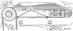
Adjusting the Drive Chain Tension
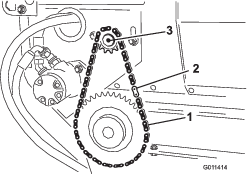
Adjust the chain tension so that it deflects 3 mm (1/8 inch). Do not overtighten the chain; this will cause chain wear. Do not operate with a loose chain, this will cause sprocket wear.
Important: The fasteners on the covers of this machine are designed to remain on the cover after removal. Loosen all of the fasteners on each cover a few turns so that the cover is loose but still attached, then go back and loosen them until the cover comes free. This will prevent you from accidentally stripping the bolts free of the retainers.
-
Remove the chain cover assembly and spacer (Figure 24).
-
Loosen bolts and nuts securing motor and sprocket assembly to the main frame (Figure 25).
-
Rotate motor and sprocket assembly, in mounting slots, until proper tension is achieved.
-
Tighten the mounting bolts.
-
Install the cover assembly and spacer.
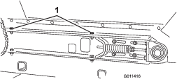
Adjusting the Conveyor Belt
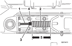
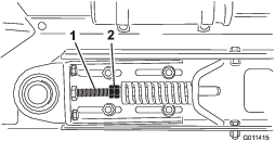
When the conveyor belt is adjusted properly, the compressed length of each compression spring should be 112 mm (4-7/16 inches). Adjust the conveyor belt as follows:
-
Loosen the jam nuts and adjust tension rod (Figure 26) nuts to attain the desired tension.
-
Tighten the jam nuts to lock the adjustment.
-
Check to ensure that the center distance between the conveyor belt roller shafts (Figure 27), on each side of machine, are equal distance—approximately 89.5 cm (35-1/4 inches).
Replacing the Conveyor Belt
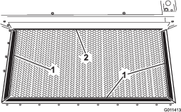
When replacing a damaged or worn conveyor belt, always inspect the hopper seals (Figure 28) and the gate edge (Figure 28) for wear or torn edges. Replace worn or torn components to ensure proper operation of the new conveyor belt.
Important: The fasteners on the covers of this machine are designed to remain on the cover after removal. Loosen all of the fasteners on each cover a few turns so that the cover is loose but still attached, then go back and loosen them until the cover comes free. This will prevent you from accidentally stripping the bolts free of the retainers.
-
Remove the chain cover assembly and spacer (Figure 29).
-
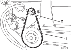
Remove the master link from the chain and remove the chain from the small sprocket (Figure 30).
Note: You may have to loosen the motor mounting bolts to disassemble the chain link.
-
Loosen the jam nuts and the nuts on the tension rod to release the spring tension (Figure 31).
-
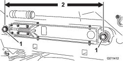
Remove 2 cap screws, washers, and nuts on each side of the machine, securing the hopper to the slider bed (Figure 32).
-
Pivot the hopper rearward and lean it against a wall, ladder, etc. Do not allow the hopper to rest against the rear of machine, as damage may result to the brush or the hydraulic couplers (Figure 33).
Important: Ensure that the hopper is pivoted beyond center and/or secured to a wall or post to prevent it from accidentally falling on the work area (Figure 33).
-
Loosen 2 cap screws, washers, and nuts on the right side of machine, securing the slider bed to the frame (Figure 34). Ensure that the fasteners are loose enough to allow the slider bed to be tipped.
-
Remove 2 cap screws, washers, and nuts on the left side of the machine, securing the slider bed to the frame (Figure 35).
-
Remove the belt as follows:
-
Cut the belt and remove it from the rollers.
or
-
Insert a plastic belt tool between each roller and the belt. Rotate the rollers until each tool is positioned to the outside of each roller. The tool must be inserted past the rib in the center of the belt.
-
Insert a lift bar into hole on left side of machine.
-
Raise the lift bar to tip the slider bed.
-
Slide the belt and belt tools off the rollers at the same time.
-
-
Install the belt as follows:
-
Insert a lift bar into hole on left side of machine and raise lift bar to tip slider bed (Figure 35).
-
Install the belt onto rollers as far as possible.
-
Insert a plastic belt tool between each roller and belt. Rotate rollers until each tool is positioned to the outside of each roller. The tool must be inserted past the rib in the center of the belt.
-
Slide the belt and belt tools onto rollers until the belt is approximately centered on the rollers.
-
Remove the belt tools from between the belt and the rollers.
-
Position belt so rib fits into alignment grooves in each roller.
-
Reverse the procedure to assemble the hopper and the chain components.
-
Adjust the belt. Refer to Adjusting the Conveyor Belt.
-
Storage
-
Thoroughly clean the machine, especially inside the hopper. The hopper and conveyor belt area should be free of any remaining sand particles.
-
Tighten all fasteners.
-
Lubricate all grease fittings and bearings. Wipe off any excess lubricant.
-
The unit should be stored out of the sun to prolong the life of the conveyor belt. When stored outside it is recommended to cover the hopper with a tarp.
-
Check the tension of the drive chain. Adjust the tension, if necessary.
-
Check the tension of the conveyor belt. Adjust the tension, if necessary.
-
When bringing the machine out of storage, check for smooth operation of belt before adding material into the hopper.
Troubleshooting
| Problem | Possible Cause | Corrective Action |
|---|---|---|
| Connecting and/or disconnecting the quick couplers is difficult. |
|
|
| It is hard to steer the vehicle. |
|
|
| The hydraulic system is leaking. |
|
|
| The attachment does not function. |
|
|