| Maintenance Service Interval | Maintenance Procedure |
|---|---|
| After each use |
|
Introduction
This machine is intended for use by professional, hired operators in commercial applications. This machine is designed primarily for working large areas on well-maintained lawns in parks, golf courses, sports fields, and on commercial grounds. Using this product for purposes other than its intended use could prove dangerous to you and bystanders.
Read this information carefully to learn how to operate and maintain your product properly and to avoid injury and product damage. You are responsible for operating the product properly and safely.
Visit www.Toro.com for product safety and operation training materials, accessory information, help finding a dealer, or to register your product.
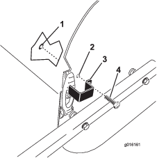
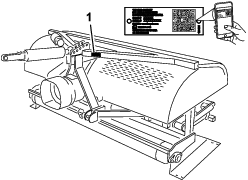
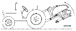
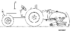
Whenever you need service, genuine Toro parts, or additional information contact an Authorized Service Dealer or Toro Customer Service and have the model and serial numbers of your product ready. Figure 1 identifies the location of the model and serial numbers on the product. Write the numbers in the space provided.
Important: With your mobile device, you can scan the QR code (if equipped) on the serial number plate to access warranty, parts, and other product information.
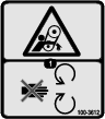
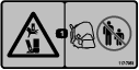
This manual identifies potential hazards and has safety messages identified by the safety-alert symbol (Figure 2), which signals a hazard that may cause serious injury or death if you do not follow the recommended precautions.

This manual uses 2 words to highlight information. Important calls attention to special mechanical information and Note emphasizes general information worthy of special attention.
This product complies with all relevant European directives when all the appropriate setup procedures have been completed; for details, please see the separate product specific Declaration of Conformity (DOC) sheet.
Warning
CALIFORNIA
Proposition 65 Warning
Use of this product may cause exposure to chemicals known to the State of California to cause cancer, birth defects, or other reproductive harm.
Safety
General Safety
This product is capable of causing personal injury. Always follow all safety instructions to avoid serious personal injury.
-
Read and understand the contents of both this Operator’s Manual and the operator’s manual of the traction unit before using this machine. Ensure that everyone using this product knows how to use this machine and the traction unit and understands the warnings.
-
Do not put your hands or feet near moving components of the machine.
-
Do not operate the machine without all guards and other safety protective devices in place and working on the machine.
-
Keep the machine a safe distance away from bystanders while it is moving.
-
Keep children out of the operating area. Never allow children to operate the machine.
-
Stop the machine, shut off the engine, engage the parking brake, remove the key, and wait for all moving parts to stop before servicing, fueling, or unclogging the machine.
Improperly using or maintaining this machine can result in injury.
To reduce the potential for injury, comply with these safety instructions
and always pay attention to the safety-alert symbol  , which means Caution, Warning,
or Danger—personal safety instruction. Failure to comply with
these instructions may result in personal injury or death.
, which means Caution, Warning,
or Danger—personal safety instruction. Failure to comply with
these instructions may result in personal injury or death.
You can find additional safety information where needed throughout this manual.
Safety and Instructional Decals
 |
Safety decals and instructions are easily visible to the operator and are located near any area of potential danger. Replace any decal that is damaged or missing. |


Setup
Removing the Aerator from the Crating
-
Remove the aerator from the crating.
-
Remove the bolts securing the aerator storage stands to the shipping pallet and remove the aerator from the pallet.
-
Remove the storage stands from the aerator. Retain them for storage use.
Note: The SR54-S and the SR70-S do not have shipping stands.
-
Place the aerator on a flat, level surface with the front roller on the ground and a block of wood positioned under the heads.
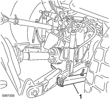
Connecting the Lower Link Arms
Parts needed for this procedure:
| Hitch pin | 2 |
| Lynch pin | 2 |
-
Ensure that the PTO is disengaged.
-
Back the traction unit squarely to the aerator until the lower link arms align with the mounting brackets.
Note: The aerator gearbox shaft should align with the traction unit PTO shaft (centered on the traction unit). If shafts misalign, adjust the lower link arms, from side to side until the shafts align.
-
Engage the parking brake, shut off the engine, and remove the key. Wait for the engine and all moving parts to stop before leaving the operator's seat.
Note: For maximum ground clearance, secure the hitch pins in the aerator at the lower mounting bracket holes, when so equipped. To determine when to use the upper mounting holes, refer to Connecting the PTO Shaft.
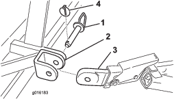
SR54 and SR54-S Aerators only
Note: The factory installs the hitch pins and lynch pins onto the SR54 and SR54-S aerators before shipping.
-
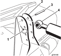
Secure the lower link arms to the aerator mounting pins with lynch pins (Figure 3).
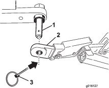
SR70, SR70-S, and SR72 Aerators only
-
Secure the lower link arms to the aerator mounting brackets with hitch pins and lynch pins (Figure 4).
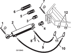
Connecting the Hydraulic Top Link
Models SR54, SR70, and SR72
Parts needed for this procedure:
| Hydraulic top link | 1 |
| Hydraulic hose—106 cm (3-1/2 ft) | 1 |
| Hydraulic hose—76 cm (2-1/2 ft) | 1 |
| Extension bracket | 2 |
| Rotational bracket | 1 |
| Hose quick couplings | 2 |
Note: Make sure that the supplied couplings are correct for the traction unit. If not, contact the traction unit manufacturer to obtain the correct couplings.
Your traction unit must have a double acting spool valve with an operator control lever and 2 quick-release couplings 12.7 mm (1/2 inch) at the rear of the traction unit. The factory provides 2 quick couplings to fit onto the hydraulic top link hoses (1/2-14 NPTF hose end thread size).
Use the procedure that follows to install the hoses and determine the need for the extension or rotation blocks. This information also helps you to determine the depth range of the aerator.
-
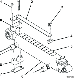
Secure the connecting link end of the hydraulic top link to the traction unit with the pins supplied with the traction unit (Figure 5).
Position the hydraulic top link so that the rod end is toward the aerator and the cylinder ports align toward the auxiliary power hydraulics of the traction unit.
Note: If you must position the hydraulic cylinder with the ports facing upward, use the rotational block instead of the standard mounting block to reposition the cylinder (Figure 5). You may use a 90° hydraulic fitting instead of the rotational block (90° fittings are not included).
Install the rotational block as follows:
-
Remove the cotter pin and pin securing the standard connecting link to the cylinder (Figure 5). Remove the connecting link from the cylinder.
-
Install the rotational block to the cylinder with the pins previously removed (Figure 5).
-
-
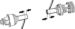
Connect the long hydraulic hose—106 cm (3-1/2 ft) to the hydraulic top link port that is closest to the aerator Figure 5. Apply pipe-thread sealing tape or compound to the hose threads to prevent any leaks.
-
Connect the short hydraulic hose—76 cm (2-1/2 ft) to the hydraulic top link port that is closest to the traction unit (Figure 5). Apply pipe-thread sealing tape or compound to the hose threads to prevent any leaks.
-
Install quick couplings to the hydraulic hoses (1/2-14 NPTF hose end thread size). Apply pipe-thread sealing tape or compound to the hose threads to prevent any leaks.
-
Connect the 2 hydraulic hose quick couplings to the ports provided on the traction unit.
-
Start the engine of the traction unit and operate the spool valve to check the extend and retract motion of the hydraulic top link.
Note: If the lifting and lowering the aerator does not agree with the traction unit control operation, reverse the hose connections at the traction unit.
-
Secure the rod end of hydraulic top link to the most forward hole possible in the aerator bracket with link pin and lynch pin (Figure 6 or Figure 7).
Important: When securing the rod end of the hydraulic link, use the most forward mounting holes in the mounting bracket so that there is enough clearance for the barrel of the cylinder when retracted.
If the hydraulic cylinder does not reach the aerator mounting bracket, use an extension block instead of the standard mounting block to connect the cylinder to the traction unit (Figure 5).
Note: If you install the extension block and need to retract the cylinder to install it, the aerator tine heads will get closer to the ground.
Install the extension blocks as follows:
Installing the Depth Gauge
Models SR54, SR70, and SR72
Parts needed for this procedure:
| Depth gauge | 1 |
| Slide block | 1 |
| Machine screw (#10 x 1/2 inch) | 2 |
| Screw (1/4 x 2-1/2 inch) | 2 |
| Tube clamp | 1 |
| Weld plate | 1 |
| Depth decal | 1 |
-
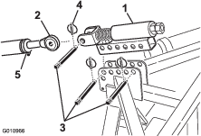
Mount the depth gauge to the flat side of the slide block with 2 machine screws (#10 x 1/2 inch), positioning the components as shown in Figure 8.
-
Using the tube clamp, weld plate and 2 screws (1/4 x 2-1/2 inches), loosely mount the depth gauge to the rod end of the top link cylinder (Figure 8). Make sure that the clamps are loose enough to allow them to rotate to the desired position.
-
Make sure that the top of the cylinder is clean enough to except the installation of a decal.
-
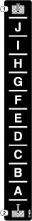
Affix the depth decal to the top of the cylinder at a location that is visible from the operating position and does not interfere with hydraulic hoses or other obstructions (Figure 8). Align the end of the decal with the letter “J” toward the aerator.
-
Check to make sure the cylinder rod can extend and retract fully without interfering with other traction unit or aerator components. When the depth gauge in positioned correctly, tighten mounting screws.
-
Run the aerator on a test plot to determine the desired setting and note the corresponding position on the depth indicator.
If needed, you can adjust the cylinder while operation the aerator to a deeper setting (toward “J”) or shallower setting (toward “A”).
Note: The letters on the decal correspond to a relative depth.
Connecting the Traction Unit Upper Link
Models SR54-S and SR70-S
Parts needed for this procedure:
| Spring-loaded top link | 1 |
| Link pin | 3 |
| Lynch pin | 3 |
-
Mount the spring-loaded top link to the aerator bracket with 2 link pins and lynch pins (Figure 9)
-
Loosen the locknut on the traction unit upper link. Adjust the upper link length until it aligns with the clevis on the spring-loaded top link of the aerator (Figure 9).
-
Connect the traction unit upper link to the clevis on the spring-loaded top link and secure with a link pin and lynch pin (Figure 9).
-
Grease the threaded steel upper link tubes.
-
Measure the length of the spring in the top link.
-
Rotate the upper link until the spring compresses approximately 13 mm (1/2 inch) (Figure 9).
-
Tighten the locknut to secure the upper link into position.
Verifying the Hydraulic Top Link Setup
Extending the hydraulic cylinder increases the tine depth.
-
Fully extend the hydraulic cylinder to determine the location of the tine heads and to verify if they contact the ground.
Note: On undulating turf, the operator can adjust the cylinder to maintain tine depth (cresting a hill) but it will be necessary to have the tine heads set about 5 cm (2 inches) below ground.
-
If the tine heads contact the ground, turf damage may occur.
If the tine heads contact the ground, adjust the location of the cylinder ends to move the top of the aerator closer to the traction unit.
-
If the tine heads do not contact the ground, you can install extension brackets (included with aerator) onto the top link to move the tine heads closer to the ground.
-
-
Retract the hydraulic cylinder to lift the tine heads.
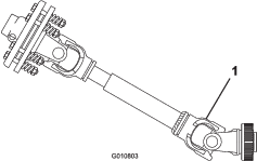
Important: When connecting the PTO, do not to lift the aerator higher than is necessary. Lifting the machine too high will cause the PTO shaft knuckles to break (Figure 10). Shut off the PTO when you raise the aerator. You can operate the PTO up to an angle of 25°, but do not exceed a 35° angle when the aerator is at its highest position; otherwise, severe shaft damage may occur.
Checking the PTO Angle
Important: Before checking the PTO angle, remove the tines.
-
With the aerator positioned on the ground and lowered to the deepest location, use an angle indictor to measure the angle between the PTO and the aerator.
-
Lift the aerator and fully retract the hydraulic top link cylinder.
-
Using an angle indictor, check the angle between the PTO and the aerator.
-
If your measurement is greater than 35°, perform 1 of the following to adjust the traction unit so that you cannot raise the aerator past 35°.
-
Use the lift stop of the traction unit (if equipped).
-
Move the lower links to a higher mounting hole (if equipped).
-
Fitting the PTO Shaft
Parts needed for this procedure:
| PTO shaft | 1 |
-
Park the traction unit and aerator on a level surface.
-
Raise the aerator completely and fully retract the hydraulic top link cylinder or upper link (Figure 11).
-
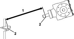
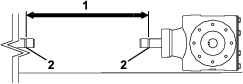
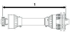
Measure the distance from the locking groove at the end of the traction unit PTO shaft to the locking groove at the aerator gearbox shaft (Figure 12).
Record this measurement here: EXAMPLE: 67 CM (26-1/2 INCHES)
-
Lower the aerator to the ground and fully extend the hydraulic top link cylinder or upper link (Figure 13).
-
Measure the distance from the locking groove at the end of the traction unit PTO shaft to the locking groove at the aerator gearbox shaft (Figure 14).
Record this measurement here: EXAMPLE: 70 CM (27-1/2 INCHES)
-
Measure the distance from the center of locking pin ball at the end of the PTO shaft to the center of the locking pin on the other end (Figure 15).
Record this measurement here: EXAMPLE: 81 CM (32 INCHES)
-
Using the smaller of the 2 measurements in Figure 14 and Figure 12, subtract that distance from the distance in Figure 15. Example: 81 cm (32 inches) minus 67 cm (26-1/2 inches) equals 14 cm (5-1/2 inches).
-
The example measurements show that the shaft is 14 cm (5-1/2 inches) too long. Add an extra 1.2 cm (1/2 inch) to ensure that the PTO shaft does not bottom out when you lift the aerator to its highest position.
EXAMPLE: 14 CM (5-1/2 INCHES) PLUS 1.2 CM (1/2 INCH) EQUALS 15 CM (6 INCHES)
-
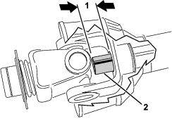
Fully slide together the PTO shaft tubes. Verify that the inside tube does not protrude into the cross and bearing section of the outer tube (Figure 16). If this happens, you need to cut off more of the inside tube—proceed to next step.
-
Measure the distance the inside tube protrudes into the cross and bearing section of the outer tube (Figure 16). Add this distance to the dimension attained in step 8.
-
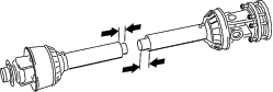
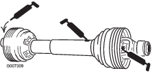
Separate the 2 halves of the PTO shaft (Figure 17).
-
Measure the distance from the end of each tube to its safety shield (Figure 17).
Record the measurements here and .
-
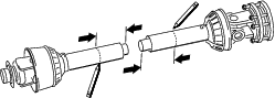
Using the dimensions determined in step 8, locate, mark, and cut off the shield and tube from each PTO half (Figure 18 and Figure 19).
Note: Cut off more of the inside tube if it protrudes into the cross and bearing section of the outer tube.
-
Using the dimensions determined in step 11, locate, mark and cut off just the safety shields to expose the tubes (Figure 20 and Figure 21).
-
Carefully remove any burrs from the ends of the tubes with a file and remove all the filings from the tubes.
-
Grease the inside tube.
Note: The telescoping tubes must always overlap by 1/2 of their length during normal operation and at least 1/3 of their length during all working conditions. During transport, when the drive line is not rotating, the telescoping tubes must have a suitable overlap to maintain alignment of the tubes and allow them to slide freely.
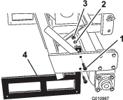
Installing the PTO Shield
Parts needed for this procedure:
| PTO shield | 1 |
-
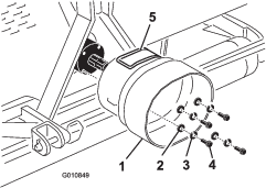
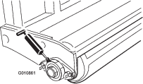
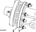
Remove the 4 bolts, lock washers, and flat washers secured to the rear of the aerator gearbox (Figure 22).
-
Mount the PTO shield to the aerator gearbox with the fasteners previously removed (Figure 22).
Align the access panel (Figure 22) of the PTO shield to the top or the side depending on the aerator frame configuration.
Connecting the PTO Shaft
Parts needed for this procedure:
| Pin (supplied with the PTO shaft) | 1 |
| Nut (supplied with the PTO shaft) | 1 |
Note: You can open the access panel (Figure 22) to ease the removal and installation of the PTO shaft mounting fasteners.
-
Remove the pin and nut from the PTO shaft (Figure 23).
-
Connect the clutch end of the PTO shaft to the aerator gearbox input shaft with pin and nut previously removed (Figure 23).
Note: You can insert pin only one way.
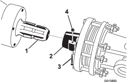
Note: Close and latch the PTO shield access panel if opened.
Note: Ensure that the pin fully inserts into the yoke of the PTO.
-
Connect the PTO shaft to the traction unit PTO shaft (Figure 24).
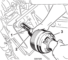
-
Slide the PTO shaft forward as far as the traction unit allows.
-
Pull back the locking collar to secure the PTO shaft in place. Slide the PTO shaft back and forth to ensure that it is properly locked.
-
Connect the shield safety chains to the PTO shield and the traction unit bracket (Figure 25). Ensure that the chains remain slack when raising and lowering the aerator.
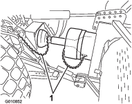
Note: To avoid excess lift, connect the lift arms of the traction unit into the top holes of the lift bracket, if equipped (Figure 26). The maximum angle on the PTO shaft is 35°.
Important: Do not lift the aerator higher than necessary when connecting the PTO. Lifting the machine too high will cause the PTO shaft knuckles to break (Figure 27). Shut off the PTO when lifting the aerator. You can operate the PTO up to a 25° angle, but never exceed a 35° angle when the aerator is at its highest position.
-
Verify that the PTO shield does not interfere with the clutch.
Adjusting the Sway Links
When installed correctly, the aerator is centered with the PTO-shaft centerline of the traction unit . Adjust the sway links to center the aerator.
Important: The PTO shaft should be as straight as possible to the traction unit PTO shaft.
-
Adjust the sway links on the lower lift arms to minimize side-to-side sway to a maximum of 25 mm (1 inch) at each side (Figure 28).
-
Adjust the lower links inboard until they contact the aerator mounting plates; refer to the traction unit operator's manual for additional installation and adjustment procedures.
Note: This reduces the stress on the pins.
-
If the traction unit has sway chains instead of sway links, install washers between the lower link arm and lynch pin to reduce the overhung load on the lift pins.
Leveling the Aerator Side-to-Side
Parts needed for this procedure:
| Level (not supplied) | 1 |
-
Park the traction unit and aerator on a firm, level surface.
-
Place a level on top of the aerator frame to check for level side-to-side (Figure 29).
-
Turn the adjustable link body (if provided) to raise or lower the link arm until the aerator levels side-to-side.
Note: Refer to the traction unit operator's manual for additional adjustment procedures.
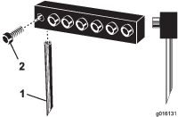
Installing the Tines
Parts needed for this procedure:
| Tines (as required) | – |
You can choose from a wide selection of tines for the aerator. Choose the tine type, size, and spacings required for the job. Refer to the Parts Catalog for the list of accessories.
-
Ensure that the stands or support blocks fully support the aerator.
-
Turn off the traction unit engine and remove the key.
-
Loosen the clamping bolts and remove the previously used tines (Figure 30).
-
Slide the new tines into the holes sized to fit the tines selected. Never use small diameter tines in the large diameter holes; the tines should fit closely in the hole. Be sure to slide the tine up into the head until it bottoms out.
Note: Position hollow coring tines with the ejection slot to the rear. Position solid tines with the tine tip angle facing the machine (Figure 30).
-
Tighten the clamping bolts firmly to secure the tines. Do not use impact tools.
-
Set the tine angle for the new tines; refer to Adjusting the Tine Angle (Models SR54, SR54-S, SR70 and SR70-S) or Adjusting the Tine Angle (Model SR72).
-
Before aerating formal turf for the first time after installing tines, test the aerator on a less important area so that you can try alternative traction unit gears and fine tune the adjustment to achieve the hole spacing and turf appearance desired.
Setting the Tine Depth
Models SR54-S and SR70-S
Set the tine depth; refer to Adjusting the Tine Depth (Models SR54-S and SR70-S).
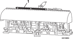
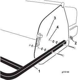
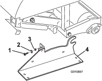
Installing the Rear Guard
Parts needed for this procedure:
| Rear guard | 1 |
| Screw (3/8 x 3-1/4 inch) | 4 |
| Flat washer (0.438 x 1 inch) | 12 |
| Locknut | 4 |
| End cap | 2 |
-
Insert the end caps into the ends of the rear guard tubes (Figure 31).
-
Align the holes in the rear guard mounting tubes with the holes in the aerator side plates (Figure 31).
Note: On SR54-S and SR70-S models, mount the ends of the tubes to the lower side plate mounting holes if the aerator tine depth is set in Position A (Figure 32). Use the upper mounting holes for depth setting Positions B or C.
-
Secure the guard mounting tubes to the side plates with 4 screws, flat washers, and nuts (Figure 31).
Note: Use the remaining washers, as required, to fill any gap between the tubes and the aerator side plates.
Removing the Storage Stands
Preparing Models SR54 and SR70
-
Raise the aerator roller(s) 7.5 to 15 cm (3 to 6 inches) off the ground. Place support blocks under the roller(s).
-
Remove the bolts, lock washers, and nuts securing the storage stands to each end of the aerator (Figure 33).
-
Remove the storage stands.
-
Use the storage stands whenever you remove the aerator from the traction unit.
Preparing Model SR72
-
Raise the aerator roller(s) 7.5 to 15 cm (3 to 6 inches) off the ground. Place support blocks under the roller(s).
-
Remove the bolts, lock washers, and nuts securing the storage stands to each end of the aerator (Figure 34).
-
Remove the storage stands.
-
Use the storage stands whenever you remove the aerator from the traction unit.
Note: When installing the storage stands, ensure that the stands mount to the inside of the roller plates so that the lower frame tube rests on the top of the stands.
Note: Models SR54-S and SR70-S do not have storage stands.
Installing the Latch Lock
CE Only
Parts needed for this procedure:
| Lock plate | 2 |
| Tap bolt | 2 |
| Retaining ring | 2 |
Applying the CE Decal and the Production Year Decal
CE Only
Parts needed for this procedure:
| CE decal | 1 |
| Production year decal | 1 |
After completing all necessary CE requirements, apply the CE decal and the production year decal next to the serial plate (Figure 36).
Product Overview
Note: Specifications and design are subject to change without notice.
| ProCore SR54 | ProCore SR54-S | ProCore SR70 | ProCore SR70-S | ProCore SR72 | |
| Weight with PTO and Top Link | 528 kg(1165 lb) | 563 kg(1242 lb) | 623 kg(1373 lb) | 679 kg(1498 lb) | 948 kg(2091 lb) |
| Working Width | 1.37 m(54 inches) | 1.37 m(54 inches) | 1.85 m(73 inches) | 1.85 m(73 inches) | 1.83 m(72 inches) |
| Working Depth (Adjustable) | 25 to 250 mm(1 to 10 inches) | 25 to 250 mm(1 to 10 inches) | 25 to 250 mm(1 to 10 inches) | 25 to 250 mm(1 to 10 inches) | 25 to 400 mm(1 to 16 inches) |
| Hole Spacing | 64 to 102 mm(2.5 to 4 inches) | 64 to 102 mm(2.5 to 4 inches) | 64 to 102 mm(2.5 to 4 inches) | 64 to 102 mm(2.5 to 4 inches) | 75 to 150 mm(3 to 6 inches) |
| Productivity | 3,345 m2/hr (36,000 ft2/hr) | 3,345 m2/hr(36,000 ft2/hr) | 4,460 m2/hr(48,000 ft2/hr) | 4,460 m2/hr(48,000 ft2/hr) | 3,530 m2/hr(38,000 ft2/hr) |
| Recommended Traction Unit Size | 16 to 18 hp | 18 hp | 25 to 35 hp | 25 to 35 hp | 45 hp |
| Recommended Lift Capacity | 544 kg(1200 lb) | 680 kg(1500 lb) | 771 kg(1700 lb) | 817 kg(1800 lb) | 1,270 kg(2800 lb) |
| Recommended Counter Weight | 70 kg(150 lb) | 70 kg(150 lb) | 115 kg(250 lb) | 115 kg(250 lb) | 135–225 kg(300 to 500 lb) |
| Recommended PTO Speed | 400 to 460 rpm | 400 to 460 rpm | 400 to 460 rpm | 400 to 460 rpm | 400 to 460 rpm |
| Actual Working Speed @ 400 PTO rpm (Varies with hole spacing) | 1.5 to 2.5 mph | 1.5 to 2.5 mph | 1.5 to 2.5 mph | 1.5 to 2.5 mph | 0.8 to 1.5 mph |
| Lift System | Std. 3-point | Std. 3-point | Std. 3-point | Std. 3-point | Std. 3-point |
Attachments/Accessories
A selection of Toro approved attachments and accessories is available for use with the machine to enhance and expand its capabilities. Contact your Authorized Service Dealer or authorized Toro distributor or go to www.Toro.com for a list of all approved attachments and accessories.
To ensure optimum performance and continued safety certification of the machine, use only genuine Toro replacement parts and accessories. Replacement parts and accessories made by other manufacturers could be dangerous, and such use could void the product warranty.
Operation
Before Operation
Note: Determine the left and right sides of the machine from the normal operating position.
Before Operation Safety
-
Never allow children or untrained people to operate or service the machine. Local regulations may restrict the age of the operator. The owner is responsible for training all operators and mechanics.
-
Become familiar with the safe operation of the equipment, operator controls, and safety signs.
-
Know how to stop the machine and shut off the engine quickly.
-
Check that the safety switches and guards are attached and functioning properly. Do not operate the machine unless they are functioning properly.
-
Before operating, always inspect the machine to ensure that the tines are properly functioning. Replace worn or damaged tines.
-
Inspect the area where you will use the machine and remove all objects that the machine could strike.
-
Locate and mark all electrical or communication lines, irrigation components, and other obstructions in the area before aerating. Remove the hazards, if possible, or plan how to avoid them.
-
Ensure that your traction unit is suitable for use with an implement of this weight by checking with your traction unit supplier or manufacturer.
-
Park the machine on a level surface; engage the parking brake; shut off the engine; remove the key; and wait for all movement to stop before making any adjustments to the machine.
Outcross Traction Unit Controls
Refer to the Outcross traction unit Operator’s Manual for information on controls and operation, as well as additional information on setting up the aerator.
Traction Unit Controls
Become familiar with operating the following traction unit controls before you operate the aerator:
-
PTO engagement
-
Engine/PTO speed
-
3-point hitch (raise/lower)
-
Auxiliary valve operation
-
Clutch
-
Throttle
-
Gear selection
-
Parking brake
Important: Refer to the traction unit operator's manual for operating instructions.
Principles of Operation
The 3-point hitch linkage/hydraulic top link on the traction unit lifts the aerator for transport and lowers it for operation.
The power takeoff (PTO) transmits power though shafts, gearbox, and O-ring drive chains to a crankshaft, that drives the tine holding arms into the turf surface.
As the traction unit travels forward with the PTO engaged and the aerator lowered, it creates a series of holes in the turf surface.
The depth of the tine penetration is determined by extending the hydraulic top link or setting the fixed top link to the desired position.
The distance between the holes created is determined by the gear ratio (or hydrostatic traction pedal position) of the traction unit and the number of tines in each tine head. Changing the engine speed does not change the hole spacing.
Traction Unit PTO Speed
The aerator is designed to operate with a PTO speed of up to 460 rpm depending on the size/weight of the tines. Most traction units indicate a 540 PTO rpm position on the rev counters. Since the engine and PTO speeds are directly proportional, you can determine the engine speed required for a 400 rpm PTO by calculating as follows:
| (Engine rpm at 540 PTO speed) x (400÷540) = required engine rpm |
For example, if the engine rpm were 2,700 for a PTO speed of 540 rpm, you would get the following:
| 2,700 x (400÷540) = 2,000 rpm |
In this example, running your traction unit at 2,000 rpm now provides you with a 400 rpm PTO speed.
If your traction unit indicates some other engine rpm at 540 PTO rpm, substitute that number for the 2,700 engine speed used in the example.
Important: The recommended PTO speed for 10-inch tines and shorter is 460 rpm and 425 rpm for tines longer than 10 inches.
Training Period
Before using the aerator, find a clear area and practice using the machine. Operate the traction unit at the recommended gear settings and PTO drive speeds and become thoroughly familiar with the machine handling. Practice starting, stopping, raising, and lowering the aerator; engaging and disengaging the PTO drive; and aligning the machine with previous passes. A practice session increases confidence in the performance of the aerator and helps ensure use of proper operating techniques when operating the machine.
If there are sprinkler heads, electrical or communication lines, or other obstructions at the job site, mark these items to ensure that they are not damaged.
Caution
Moving parts can cause personal injury.
To avoid personal injury, do not leave the operator’s seat without first disengaging the PTO drive, engaging the parking brake, and shutting off the engine. Do not perform aerator repairs without first lowering the aerator onto the storage stand or appropriate blocking or jacks. Secure all safety devices in their proper place before resuming operation.
Before Aerating
Locate and mark all electrical or communication lines, irrigation components, and any other underground hazards.
Inspect the area of operation for hazards that could damage the machine and remove them, if possible, or plan how to avoid them. Carry replacement tines, spring wires, springs and tools in case tines are damaged due to contact with foreign materials.
Important: Do not operate the aerator in reverse or when it is in the raised position.
During Operation
During Operation Safety
-
The owner/operator can prevent and is responsible for accidents that may cause personal injury or property damage.
-
Wear appropriate clothing, including eye protection; long pants; substantial, slip-resistant footwear; and hearing protection. Tie back long hair and do not wear loose clothing or loose jewelry.
-
Use your full attention while operating the machine. Do not engage in any activity that causes distractions; otherwise, injury or property damage may occur.
-
Do not operate the machine when tired, ill, or under the influence of alcohol or drugs.
-
Never carry passengers on the machine and keep bystanders and pets away from the machine during operation.
-
Operate the machine only in good visibility to avoid holes or hidden hazards.
-
Keep your hands and feet away from the tines.
-
Park the machine on a level surface; engage the parking brake; shut off the engine; remove the key; and wait for all movement to stop before adjusting, cleaning, storing, or repairing the machine.
-
Look behind and down before backing up to be sure of a clear path.
-
Stop the machine, shut off the engine, wait for all moving parts to stop, and inspect the tines after striking an object or if there is an abnormal vibration in the machine. Make all necessary repairs before resuming operation.
-
The aerator is heavy. When attached to a traction unit and in the raised position, its weight affects stability, braking and steering. Exercise caution when transporting between working areas.
-
Always maintain proper traction unit tire pressure.
-
Ensure that you comply with all regulations before transporting equipment on the public roads and highways. Make sure that all required reflectors and lights are in place and are clean and visible by overtaking and oncoming traffic.
-
Reduce speed on rough roads and surfaces
-
Locked together independent wheel brakes when transporting.
-
For all PTO shaft steel parts (tubes, bearings, joints, etc.) disassembly or repairs, it is highly advisable to contact your authorized Toro distributor. Removal of components for repairs and reassembly may damage some parts if not performed with special tools by trained technicians.
-
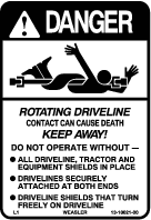
Do not use the PTO shaft without the guards supplied.
-
Friction clutches may become hot during use; do not touch them. To avoid the risk of fire, keep the area around the clutch free of flammable material and avoid prolonged slipping of the clutch.
Slope Safety
-
Review the traction unit specifications to ensure that you do not exceed its slope capabilities.
-
Slopes are a major factor related to loss of control and rollover accidents, which can result in severe injury or death. You are responsible for safe slope operation. Operating the machine on any slope requires extra caution.
-
Evaluate the site conditions to determine if the slope is safe for machine operation including surveying the site. Always use common sense and good judgment when performing this survey.
-
Review the slope instructions listed below for operating the machine on slopes and review the conditions to determine whether you can operate the machine in the conditions on that day and at that site. Changes in the terrain can result in a change in slope operation for the machine.
-
Avoid starting, stopping, or turning the machine on slopes. Avoid making sudden changes in speed or direction. Make turns slowly and gradually.
-
Do not operate a machine under any conditions where traction, steering, or stability is in question.
-
Remove or mark obstructions such as ditches, holes, ruts, bumps, rocks, or other hidden hazards. Tall grass can hide obstructions. Uneven terrain could overturn the machine.
-
Be aware that operating the machine on wet grass, across slopes, or downhill may cause the machine to lose traction. Loss of traction to the drive wheels may result in sliding and a loss of braking and steering.
-
Use extreme caution when operating the machine near drop offs, ditches, embankments, water hazards, or other hazards. The machine could suddenly roll over if a wheel goes over the edge or the edge caves in. Establish a safety area between the machine and any hazard.
Aerating Procedures
Important: If you stored the machine for an extended period, ensure that the PTO slip is operational. Refer to Adjusting the PTO Clutch.
-
Lower the aerator so that the tines are near the ground at the lowest part of their stroke.
-
At a low traction unit engine speed, engage the power takeoff (PTO) clutch to start the aerator working.
-
Select a gear that produces a 1 to 4 km/h ( 0.8 to 2.5 mph) forward speed at the rated PTO speed of 400 to 460 rpm; refer to the operator's manual for the traction unit.
-
As you release the clutch and the traction unit moves forward, lower the aerator fully onto the roller(s) and increase engine speed to give a maximum of 400 to 460 rpm (460 on model SR72) at the PTO.
Important: Never operate the traction unit PTO more than 460 rpm or you may damage to the aerator.
Important: Make sure that the roller is always on the ground when the aerator is operating.
-
Note the hole pattern. If you require greater hole spacing, increase forward the speed of the traction unit by shifting up a gear or with a hydrostatic drive traction unit, actuate the hydrostat lever or pedal to give faster speed. For closer hole spacing, decrease traction unit forward speed.
Important: Changing the engine speed while in the same gear will not change the hole pattern.Look behind the aerator frequently to ensure that the machine operates properly, and it aligns with previous passes.
-
Use the front traction unit wheel as a guide to maintain equal lateral hole spacing with the previous pass.
-
At the end of the aeration pass, raise the aerator and quickly disengage the PTO.
-
If you back into a tight area (like a tee box), disengage the PTO and raise the aerator to its highest position.
Important: Never aerate in reverse.
-
Always clear the area of all damaged machine parts, such as broken tines, etc., to prevent mowers or other turf maintenance equipment from picking up and throwing debris.
-
Replace broken tines, inspect, and correct damage to those still usable. Repair any other machine damage before continuing operation.
Subsoil Cultivation
The spading motion of the tine creates subsoil cultivation, fracturing, or heaving as the aerator and traction unit move forward. Quality of finish on the playing surface after aerating will depend on various factors including turf condition, root growth and moisture content.
Hard Ground
If the ground is too firm to obtain the desired aeration depth, the coring head can get into a bouncing rhythm. This is due to the hard pan that the tines are attempting to penetrate. Correct this condition by using one or more of the following recommendations:
-
You obtain the best results after a rain or after watering the turf the previous day.
-
Reduce the number of tines per stomper arm. Attempt to maintain a symmetrical tine configuration to evenly load the stomper arms.
-
Reduce aerator penetration (depth setting) if ground is hard packed. Clean up cores, water turf, and aerate again at a deeper penetration.
Aerating soil built on top of hard subsoils (i.e., sand/soil cap placed over rocky ground) can cause undesired hole quality. This occurs when the aeration depth is greater than what the tines can penetrate through the soil cap and the subsoil. When the tines contact hard subsoil, the aerator may lift and cause the top of the holes to become elongated. Reduce the aeration depth sufficiently to avoid penetration into the hard subsoil.
Longer/Larger Tines
25 cm (10 inches) or More
Using longer/larger tines can leave the front or rear of the hole tufted or slightly deformed.
-
Hole quality for this configuration improves if you reduce the coring head speed 10 to 15% from full operating speed. For PTO powered aerators, reduce the engine speed until the PTO speed is 400 to 420 rpm.
Note: Reducing the engine speed does not affect the forward spacing.
-
The position of the camber bracket can affect pushed holes; refer to Adjusting the Tine Angle (Models SR54, SR54-S, SR70 and SR70-S) or Adjusting the Tine Angle (Model SR72).
Multi Row Adapter Heads
When using multi-row adapter heads, reduce the engine speed until the PTO speed is 400 to 420 rpm.
Note: Reducing the engine speed does not affect the forward spacing.
Root Zone Lifting
Using multi-tine heads in conjunction with larger coring tines or large diameter solid tines can induce significant stress on the root zone of the turf. This stress can fracture the root zone and cause a lifting action to the turf. If lifting damage occurs, try one or more of the following:
-
Reduce tine density—remove some of the tines
-
Decrease coring depth—in 13 mm (1/2 inch) increments (suggested)
-
Increase forward hole spacing—change transmission of the traction unit up one gear
-
Decrease the tine diameter—solid or coring
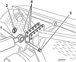
Adjusting the Tine Angle (Models SR54, SR54-S, SR70 and SR70-S)
Set the tine angle according to the tine length by using one of the 2 adjustment holes in the linkage arm. These holes are presets only. When using 17.8 mm (7 inch) to 25.4 mm (10 inch) tines, position the head bumper closest to the rear of the tine head. You may need to use the other position—the hole farthest from the head (Figure 37) due to variances of soil conditions.
-
Disengage the PTO and engage the parking brake.
-
Shut off the engine and remove the key from ignition switch.
-
Release the spring tension to the tine head (Figure 37).
-
Remove the bumper bolt and bumper from the linkage arm and reinsert them into the other adjustment hole (Figure 37).
-
Connect the spring tension to the tine head.
Adjusting the Tine Angle (Model SR72)
Set the camber bracket (Figure 38) to the correct position based on the tine length. The head stop is set to 1 of 5 predetermined positions by choosing the hole through which you bolt the adjustment rod. These holes are presets only; for instance, by using a 10-inch tine in the 12-inch position you may achieve a smoother finish; depending on the application.
-
Disengage the PTO and engage the parking brake.
-
Shut off the engine and remove the key.
-
Release the spring tension to the tine head (Figure 38).
-
Remove the nut and bolt at the adjustment holes in the camber bracket (Figure 38).
-
Rotate the camber bracket until it aligns with the desired hole in the arm, and install the bolt and nut.
Note: Make sure that the bolt goes through the camber bracket and plate.
-
Connect the spring tension to the tine head.
Adjusting the Tine Depth (Models SR54-S and SR70-S)
You can change the tine depth by raising or lowering the rear roller. You can adjust the roller height by moving the roller adjusting bolts to the desired position.
Note: The factory ships the aerator in Position A.
-
Position A - Maximum depth
-
Position B - The depth decreases 38 mm (1-1/2 inches) from Position A
-
Position C - The depth decreases 76 mm (3 inches) from Position A
Adjusting the Tine Depth (Models SR54, SR70, and SR72)
Start the tractor engine and operate the tractor spool valve to check the extend and retract motion of the hydraulic top link.
Note: Reverse the hose connections, at the tractor, if they do not agree with the tractor control operation.
Run the aerator on a test plot to determine the desired setting and note the corresponding position on the depth indicator.
If needed, you can adjust the cylinder while operation the aerator to a deeper setting (toward “J”) or shallower setting (toward “A”).
Note: The letters on the decal correspond to a relative depth.
Note: Extending the cylinder makes the aerator penetrate deeper.
Adjusting the Head Return Springs
You can adjust the head return springs to increase or decrease the tension. Moving the spring toward the front of the aerator increases the spring tension, thus increasing the distance between the spring mounting posts.
-
Disengage the PTO and engage the parking brake.
-
Shut off the engine and remove the key.
-
Release the spring tension to the linkage arm.
-
Remove the nut securing the spring mounting post bolt to the linkage arm (Figure 41 or Figure 42).
-
Remove the mounting post bolt and the mounting post from the linkage arm and reinsert them into the another adjustment hole (Figure 41 or Figure 42).
-
Install the nut securing the spring mounting post bolt to the linkage arm.
-
Connect the spring tension to the linkage arm.
Transport Operation
To begin transport operation, raise the aerator and disengage the PTO. To avoid loss of control, traverse steep inclines slowly, approach rough areas at reduced speed and cross severe undulations carefully.
Important: Do not exceed transport speeds of 24 km/h (15 mph).
Operating Tips
Caution
Improperly using or maintaining this machine can result in injury.
-
Before leaving operator’s seat disengage the PTO drive, engage the parking brake, shut off the engine, remove the key, and wait for all moving parts to stop.
-
Do not perform aerator adjustments or repairs without first lowering the aerator onto the safety stand.
-
Ensure that you secure all safety devices in their proper place before resuming operation.
-
Carry replacement tines, spring wires, springs, and tools in case the tines are damaged due to contact with foreign materials.
-
Engage the PTO at low engine speed. Increase the engine speed to achieve the desired PTO speed of 400 to 460 rpm (maximum) and lower the aerator. Operate at an engine speed at which the aerator runs most smoothly.
Note: Changing the engine/PTO speed in a particular traction unit gear (or fixed hydrostatic pedal position on traction units with hydrostatic transmission) does not change the hole spacing.
-
Make very gradual turns when aerating. Never make sharp turns with PTO drive engaged. Plan your aeration path before lowering the aerator. Making sharp turns while aerating will damage the aerator and the tines.
-
If the engine/PTO load raises when operating the machine on hard ground or going uphill, raise the aerator slightly until engine/PTO regains speed, then lower the aerator again.
-
Best results are achieved when the tine entry is on a slight incline toward the rear of the machine. Use caution when extending the hydraulic top link to keep from hammering the turf with the tine heads. In some cases, you may not achieve the best results from using the preset holes in the camber brackets, especially where the grass roots are short or weak. You may want to experiment using another camber setting that will set the tines on more of an incline to keep from pulling soil out of the hole.
-
Do not aerate if the ground is too hard or dry. You will obtain the best results aerating after a rain or after watering the turf the previous day.
Note: If the roller rides up off the ground while aerating, the ground is too hard to achieve the desired depth; reduce the aeration depth until the roller contacts the ground during operation.
-
Raise the aerator penetration if the ground is hard packed. Clean up the cores and aerate again at a deeper penetration, preferably after watering.
-
Look behind frequently to ensure that the machine is operating properly and that it is aligned with previous passes. A loss of one line of holes indicates a bent or lost tine. Inspect after each pass.
-
To prevent mowers or other turf maintenance equipment from being picking up and throwing debris, always clear the area of all damaged machine parts, such as broken tines, etc.
-
Replace broken tines; inspect and repair damage to usable tines. Repair any other machine damage before resuming operation.
After Operation
After Operation Safety
-
Park the machine on a level surface; engage the parking brake; shut off the engine; remove the key; and wait for all movement to stop before leaving the machine.
-
Keep all parts of the machine in good working condition and all hardware tightened.
-
Replace all worn, damaged, or missing decals.
Cleaning and Inspecting the Machine
Important: Do not power wash the machine. Excessive water pressure may contaminate the grease and damage the seals and bearings.
-
Thoroughly wash the machine with a garden hose without a nozzle.
-
Use a brush to help remove dirt and debris.
-
Use mild detergent to clean the covers.
-
-
Inspect for machine damage, oil leakage, and component and tine wear.
Important: Repair all damages and worn components.
-
Grease PTO shaft joints and roller bearings; refer to Greasing the PTO Shaft and Roller Bearings.
-
Remove, clean, and coat the tines with oil.
-
Spray a light oil mist to coat the coring head bearings, crank, and damper links.
-
Clean and coat the springs with a dry lubricant like graphite or silicone.
Maintenance
Recommended Maintenance Schedule(s)
| Maintenance Service Interval | Maintenance Procedure |
|---|---|
| After the first 50 hours |
|
| Before each use or daily |
|
| After each use |
|
| Every 50 hours |
|
| Every 500 hours |
|
| Before storage |
|
| Yearly |
|
Maintenance Safety
-
Before servicing or adjusting the machine, stop the machine, shut off the engine, engage the parking brake, remove the key, and wait for all moving parts to stop.
-
Perform only those maintenance instructions described in this manual. If you need to make major repairs top the machine or need assistance, contact an authorized Toro distributor.
-
Ensure that the machine is in safe operating condition by keeping the hardware tight.
-
If possible, do not perform maintenance while the engine is running. Keep away from moving parts.
-
Do not check or adjust the chain tension when the traction unit engine is running.
-
Carefully release pressure from components with stored energy.
-
Support the machine with blocks or storage stands when working beneath it. Never rely on the hydraulic system to support the machine.
-
Check the tine mounting bolts daily to ensure that they are tightened to specification.
-
After maintaining or adjusting the machine, install all guards, shut the hood, and secure it.
Lifting the Machine
Caution
If you do not fully support the machine, it may move or fall, which may result in personal injury.
-
When changing attachments or performing other service, use correct blocks, hoists, or jacks.
-
Parked the machine on a solid level surface such as a concrete floor.
-
Prior to raising the machine, remove any attachments that may interfere with the safe and proper raising of the machine.
-
Always chock or block the wheels of the traction unit.
-
Use storage stands or blocks to support the raised machine.
Note: You can use a hoist to lift the aerator. Use the coring head eyelet as a hoist attachment point (Figure 43). Ensure that the hoist has enough lift capacity. Refer to Specifications.
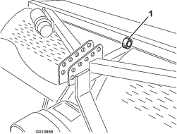
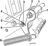
Greasing the PTO Shaft and Roller Bearings
| Maintenance Service Interval | Maintenance Procedure |
|---|---|
| Every 50 hours |
|
Grease specification: SAE multipurpose, high-temperature grease with high-pressure (EP) performance or SAE multipurpose lithium grease
PTO shaft joints (3 grease fittings); refer to Figure 44
Roller bearings (2 or 4 grease fittings, depending on your aerator model); refer to Figure 45
O-ring chain — Do not grease the chain.
Gearbox Oil Specification
High quality 80W-90 gear oil or equivalent.
Checking the Gearbox Oil
| Maintenance Service Interval | Maintenance Procedure |
|---|---|
| Every 50 hours |
|
-
Allow the gearbox to cool before checking the oil level.
-
Clean debris from the fill plug and check plug to avoid contamination.
-
Remove the check plug from the gearbox (Figure 46).
Note: If the gearbox has 2 check plugs, use the lower plug.
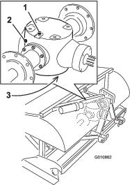
-
Ensure that oil is up to the bottom of the check plug hole in the gearbox (Figure 46).
-
If the oil level is low, remove the vent/fill plug from top of the gearbox and add the specified gear oil as required.
-
Install the plugs.
Changing the Gearbox Oil
| Maintenance Service Interval | Maintenance Procedure |
|---|---|
| After the first 50 hours |
|
| Every 500 hours |
|
-
Clean debris from vent/fill plug and drain plug to avoid contamination (Figure 46).
-
Remove the vent/fill plug to relieve air draw.
-
Position a drain pan under the drain plug and remove the plug.
Note: The high viscosity of cool oil extends the drain time (approximately 30 minutes).
-
After the oil is completely drained, install the drain plug.
-
Fill the gearbox with the specified gear oil. Use the chart that follows to determine the gearbox-oil capacity.
Model Gearbox-Oil Capacity SR54 1.9 L (2 US qt) SR54-S 1.9 L (2 US qt) SR70 1.9 L (2 US qt) SR70-S 1.9 L (2 US qt) SR72 3.8 L (4 US qt) -
Install the vent/fill plug.
-
Check the oil level and add oil as needed.
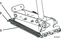
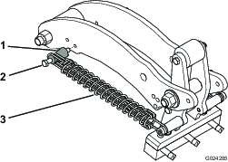
Inspecting/Adjusting the Drive Chain
| Maintenance Service Interval | Maintenance Procedure |
|---|---|
| Before each use or daily |
|
-
Check the drive chain for wear and damage.
Replace a worn of damage drive chain.
-
Check the drive chain tension.
The chain should move approximately 13 mm (1/2 inch) of overall deflection, or 6 mm (1/4 inch) in each direction. If the chain tension is more than or less than 13 mm (1/2 inch) of overall deflection, adjust the tension; refer to Adjusting the Drive Chain.
-
Check the drive chain for rust and freedom of movement. If the chain is rusty and stiff, lubricate it; refer to Lubricating the Drive Chain.
Adjusting the Drive Chain
Chain tension can be adjusted by slightly loosening the main jam nut and tightening the jam rod to desired position (Figure 47 or Figure 48). Do not adjust the chain tension when the chain is hot or warm.
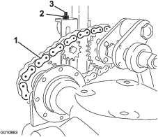
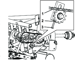
Important: Do not overtighten the chains; excess tightening of chains can cause gearbox/sprocket damage.
Lubricating the Drive Chain
Do not lubricate the drive chain unless it becomes stiff because of rust. If the chain rusts, lubricate it lightly with a dry-type lubricant.
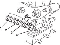
Adjusting the PTO Clutch
| Maintenance Service Interval | Maintenance Procedure |
|---|---|
| Yearly |
|
Warning
Friction clutches may become hot during use.
Do not touch. To avoid the risk of fire, keep the area around the clutch free of flammable material and avoid prolonged slipping of the clutch.
-
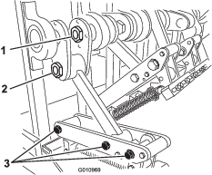
At the end of the season, back off each of the clutch nuts 2 turns (Figure 49).
-
At the start of the new season, start the PTO and allow the clutch to slip for a few seconds before stopping the PTO. Turn back the nuts an additional 2 turns.
Note: Do not allow the clutch to slip for an extended amount of time.
-
If the clutch continues to slip after turning back the nuts, tighten each nut an additional 1/4 turn until the slipping ceases. Do not overtighten the nuts, as shaft damage may occur.
Fastener Torque Specifications
| Models SR54, SR54-S, SR70, and SR70-S | SR72 | |
| Crank shaft nut | 1288 N∙m (950 ft-lb) | 1627 N∙m (1200 ft-lb) |
| Crank pin nut | 1288 N∙m (950 ft-lb) | 1288 N∙m (950 ft-lb) |
| Hinge bolt | 359 N∙m (265 ft-lb) | 407 N∙m (300 ft-lb) |
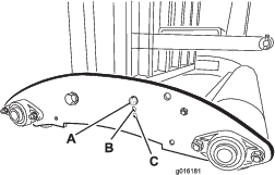
Checking the Springs
| Maintenance Service Interval | Maintenance Procedure |
|---|---|
| Before each use or daily |
|
Check the springs for crossed or broken wires (Figure 51). Crossed or broken spring wires will cause an erratic hole pattern in the turf.
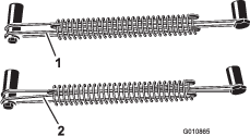
Note: The aerator includes replacement wires. The wires are a consumable item.
Adjusting the Hole Spacing
The forward hole spacing is determined by the traction unit gear ratio (or the hydrostatic traction pedal)
Note: Changing the engine speed does not affect the forward spacing.
The lateral hole spacing is determined by the number of tines in the tine heads.
Removing the Aerator from the Traction Unit
-
Stop the aerator on a level surface, not on a slope.
-
Disengage the PTO and engage the parking brake.
-
Raise the aerator roller(s) 7.5 to 15 cm (3 to 6 inches) off the ground. Place support blocks under the roller(s).
-
Shut off the engine and remove the key.
-
Before leaving the operator's seat, shut off the engine, remove the key, and wait for all moving parts to stop.
-
Remove the tines.
-
Install the storage stand.
-
Slowly lower the aerator until the storage stands contact the ground.
-
Remove the pin securing the top link to the aerator bracket. Retain the pin with the aerator.
Also, on models with a hydraulic top link, disconnect the hydraulic hoses and the connecting link from the traction unit. Cap the hydraulic hoses. Store these components with the aerator.
-
Disconnect the safety shield chains from PTO shaft.
-
Pull back on the lock collar to disconnect the power shaft from the traction unit PTO shaft.
-
Slide the PTO shaft back and remove it from the traction unit.
-
Connect the PTO safety chain to the aerator to prevent the PTO shaft from contacting the ground.
-
Remove the pins securing the lower link arms to the aerator brackets. Retain the pins with the aerator.
Troubleshooting
| Problem | Solution |
| The springs are breaking or not pulling back the head to normal position. | Slow the PTO speed of the traction unit. The longer and heavier the tines, the greater the centrifugal force on the head. Check for crossed or broken spring wires. |
| The tines produce elongated or picking holes. | Adjust the angle of the tine or change the traction unit ground speed. Make sure that you can lower the aerator at least 5 cm (2 inches) below flat ground level to allow for undulation. |
| The tines are hitting the ground with an erratic pattern. | • Check for crossed or broken spring wires.• Slow the PTO speed of the traction unit. |
| The PTO clutch slips excessively. | Adjust the tines to a shallower depth. Review the clutch adjustment procedure. Replace PTO clutches. |
| The turf is pulling up with coring tines. | Shallow-rooted turf may require solid tines the first time. |
| The soil is too hard for full penetration. | Aerate at a depth that the machine can achieve, water overnight, and then increase the depth. Repeat if needed until you can aerate the soil at the desired depth. |
| The coring tines are breaking. | You are trying to get too much depth for the soil condition. See above and aerate to a shallower depth. |
| The tines do not stay in the head. | Tighten the tine holder bolts; do not use jam nuts or an impact wrench. If the bolt does not hold the tine, replace it. |
| The tines pull the soil up when the machine raises. | Raise the machine part of the way out of the soil before disengaging the PTO. |
| The machine does not turn. | Ensure that the PTO, driveshaft, and drive chains are working properly. |
| The traction unit has difficulty lifting the aerator. | Move the traction unit lift arms 7.5 to 10 cm (3 to 4 inches) closer to the aerator. Ensure that the traction unit has the capacity to lift the aerator. |
| The hydraulic top link cylinder is spongy. (It “gives” and moves in and out a short span when applying hydraulic pressure. | Bleed air is from the cylinder or lines. |
| The machine is noisy or knocking. | •The crank pin nut has vibrated loose. •The chains are too loose.•The bolts on the bottom of the frame at the rear of the main arm have vibrated loose.•Check the oil level in the gearbox. |
| The hydraulic top link cylinder cannot be fully retracted (PTO shaft jams). | The PTO shaft is too long for your traction unit. Cut PTO shaft to the correct length. |
| The traction unit is difficult to steer when in transport. | •Add weight to the front of the traction unit.•Check the tire pressure and adjust it as required. |
| The camber bracket is damaged. | •Do not store the aerator on the ground with tines installed.•Do not run the coring head at high speed for an extended time when the tines are out of the ground. |
Storage
Storage Safety
-
Park the machine on a level surface; engage the parking brake; shut off the engine; remove the key; and wait for all movement to stop before leaving the machine.
-
Store the machine on the storage stands positioned on a firm, level surface so that it does not sink or tip over.
-
Do not allow children to play on or around the stored machine.
Storing the Machine
At the end of an aerating season or when storing the aerator for a long period, do the following preventative maintenance steps:
-
Clean off any dirt or grease that may have accumulated on the machine or any of the moving parts.
-
Remove and clean out the tines. Coat the tines and tine fasteners with oil to prevent rusting during storage.
-
Open the hood and clean out the inside of the machine.
-
Lubricate all grease fittings and tine fastener screw threads.
-
Store the machine on the provided storage stands on a hard, dry surface.
-
Loosen the PTO clutch bolts 2 turns.
-
Connect the PTO safety chain to the aerator in the stored position to prevent damage or remove the PTO and store it under the hood to minimize corrosion.
-
Paint the roller and touch up any other scratches on the painted surfaces.
-
Replace any missing or damaged decals.
-
Store the aerator inside a dry, secure building. Inside storage will reduce maintenance, give a longer working life, and increase the residual value of the machine. If inside storage is not available, cover the machine with a heavy sheet or tarpaulin and secure tightly.