Safety
Safety and Instructional Decals
 |
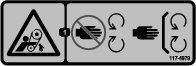
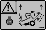
Safety decals and instructions are easily visible to the operator and are located near any area of potential danger. Replace any decal that is damaged or missing. |
Setup
Preparing the Machine
-
Park the machine on a level surface.
-
Engage the parking brake.
-
Shut off the engine.
-
Disconnect the spark plug wire from the spark plug.
Removing the Existing Belt and Cutter Wheel
Note: Discard all removed parts unless indicated otherwise.
-
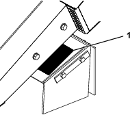
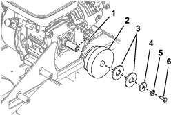
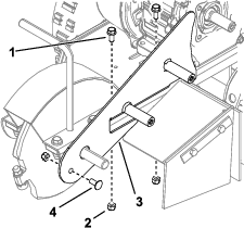
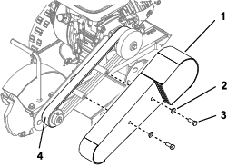
Remove the 2 bolts, 2 washers, and belt guard (Figure 1).
-
Loosen, or remove and retain, the 4 carriage bolts, 4 washers, and 4 locknuts securing the engine to the frame (Figure 2).

-
Loosen the jam nut on the tensioner bolt (Figure 2).
-
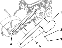
Remove the belt (Figure 1).
-
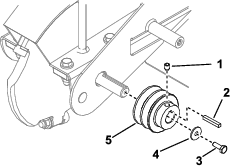
Remove the clutch pulley (Figure 3).
Note: Remove and retain the square key for later installation.
-
Remove the front pulley (Figure 4).
-
Remove the guard plate (Figure 5).
-
Remove the cutter wheel (Figure 6).
Installing the Wheel Teeth
Parts needed for this procedure:
| Wheel Tooth Kit | 1 |
| Cutter wheel | 1 |
Refer to the Installation Instructions for the kit to install the wheel teeth to the cutter wheel.
Installing the Cutter Wheel and Belt
Parts needed for this procedure:
| Bearing assembly | 2 |
| Bolt (3/8 x 1-1/2 inches) | 4 |
| Washer (0.40 x 0.81 x 0.11 inches) | 8 |
| Locknut (3/8 inch) | 4 |
| Guard plate | 1 |
| Flange bolt (5/16 x 3/4 inch) | 2 |
| Carriage bolt (5/16 x 3/4 inch) | 1 |
| Locknut (5/16 inch) | 3 |
| Front pulley | 1 |
| Square key | 1 |
| Washer (0.27 x 0.89 x 0.09 inches) | 1 |
| Bolt (1/4 x 3/4 inch) | 1 |
| Clutch pulley | 1 |
| Washer (0.76 x 1.26 x 0.07 inches) | 2 |
| Washer (0.32 x 1.12 x 0.18 inches) | 1 |
| Washer (0.31 x 0.78 x 0.07 inches) | 1 |
| Bolt (5/16 x 1-1/8 inch) | 1 |
| Belt | 1 |
| Belt guard | 1 |
| Bolt (3/8 x 1 inch) | 2 |
| Washer (0.38 x 0.75 x 0.08 inches) | 2 |
-
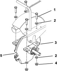
Slide a bearing assembly onto the shaft on both sides of the cutter wheel and follow the instructions provided with the bearing assemblies (Figure 7).
-
Secure the bearings to the frame of the machine using 4 bolts (3/8 x 1-1/2 inches), 8 washers (0.40 x 0.81 x 0.11 inches), and 4 locknuts (3/8 inch) as shown in Figure 7. Torque to 60 to 76 N∙m (44 to 56 ft-lb).
-
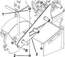
Install the guard plate using 2 flange bolts (5/16 x 3/4 inch), 1 carriage bolt (5/16 x 3/4 inch) and 3 locknuts (5/16 inch) as shown in Figure 8.
-
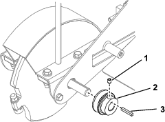
Apply thread-locking compound to the bolt (1/4 x 3/4 inch) and use the bolt, washer (0.27 x 0.89 x 0.09 inches), and square key to install the front pulley, with the pulley face flush with the end of the shaft (Figure 9). Torque the bolt to 13.6 N∙m (120 in-lb).
-
Apply thread-locking compound to the set screw, and secure the pulley with the set screw, washer (0.27 x 0.89 x 0.09 inches), and bolt (1/4 x 3/4 inch) as shown in Figure 9. Torque the setscrew to 14.9 to 17.6 N∙m (132 to 156 in-lb).
-
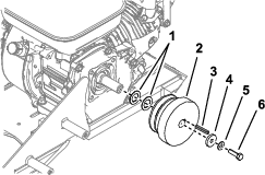
Apply thread-locking compound to the bolt (5/16 x 1-1/8 inch) and use the bolt, 2 washers (0.76 x 1.26 x 0.07 inches), 1 washer (0.32 x 1.12 x 0.18 inches), 1 washer (0.31 x 0.78 x 0.07 inches) and the square key to install the clutch pulley (Figure 10). Torque the bolt to 22.6 to 28.2 N∙m (200 to 250 in-lb).
-
Install the belt around the front pulley and clutch pulley (Figure 13).
-
Tighten the jam nut on the tensioner bolt (Figure 11).

-
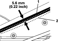
Push down on the belt to check the tension (Figure 12). You should be able to push the belt down 5.6 mm (0.22 inch) using 3.4 kg (7.4 lb) of force. Adjust the tensioner bolt as necessary to tighten or loosen the belt.
-
Install or tighten the fasteners securing the engine to the frame (Figure 11).
Note: Ensure that the engine does not twist in the chassis and the clutch pulley is aligned with the belt.
-
Install the belt guard using 2 bolts (3/8 x 1 inch) and 2 washers (0.38 x 0.75 x 0.08 inches) as shown in Figure 13.
Installing the Decal
Parts needed for this procedure:
| Decal | 1 |
Install a new decal over the existing decal on the wing bracket as shown in Figure 14.