Warning
CALIFORNIA
Proposition 65 Warning
Use of this product may cause exposure to chemicals known to the State of California to cause cancer, birth defects, or other reproductive harm.
Safety
Safety and Instructional Decals
 |
Safety decals and instructions are easily visible to the operator and are located near any area of potential danger. Replace any decal that is damaged or missing. |

Setup
Preparing the Machine
Caution
If you leave the key in the switch, someone could accidently start the engine and seriously injure you or other bystanders.
Remove the key from the switch before you perform any maintenance.
-
Park the machine on a level surface, engage the parking brake, lower the cutting units, shut off the engine, remove the key, and wait for all movement to stop before leaving the operator’s seat.
-
Unlatch and open the hood.
-
Allow the engine and radiator to cool completely.
Accessing the Machine
Removing the Hood
-
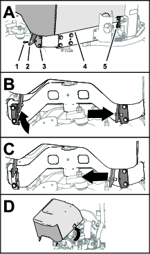
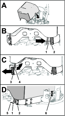
Close the hood, but do not secure the latches (Figure 1).
-
Remove the hairpin from the pin of the right hood-pivot bracket (Figure 1).
-
Move the hood to the right, from the left hood support, and raise the left hood-pivot bracket (Figure 1).
-
Move the hood to the left, from the right hood support, and raise the right hood-pivot bracket (Figure 1).
-
Remove the hood from the machine (Figure 1).
Removing the Operator’s Seat
-
At the back of the operator’s seat, remove the 2 flange-head capscrews that secure the heat shield and seat straps cross tube, and remove the heat shield (Figure 2).
-
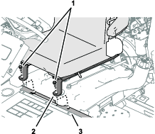
Remove the 2 flange-head capscrews that secure the seat straps to the support channel (Figure 3).
-
Tip the seat forward to access the bottom of the seat.
-
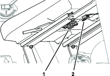
Remove the 2-socket connector from the terminals for the seat switch (Figure 4).
-
Remove the seat from the machine.
Removing the Console Cover
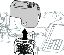
Lift the console cover from the console control panel (Figure 5).
Draining the Coolant and the Hydraulic Fluid
Draining the Radiator
Drain pan capacity: 7 quarts or more.
-
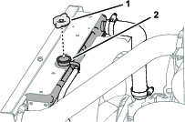
Remove the radiator cap from the radiator filler neck (Figure 6).
You no longer need the radiator cap.
-
Align a drain pan of the specified capacity below the radiator drain valve and open the valve (Figure 7).
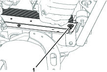
-
Allow the radiator to drain the coolant completely.
-
Close the drain valve (Figure 7).
-
Dispose of used coolant at a certified recycling center, hazardous waste facility, or according to your state and local regulations.
Removing the Coolant Reservoir Tank
-
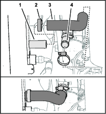
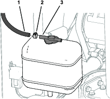
Remove the hose clamp that secures the hose to the radiator overflow fitting, and remove the hose from the fitting (Figure 8).
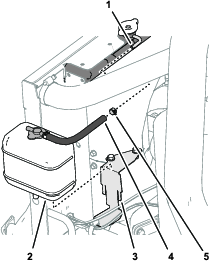
-
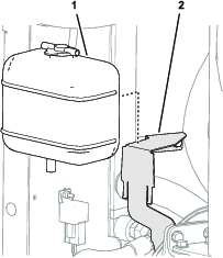
Lift the reservoir from the reservoir bracket and remove the reservoir from the machine (Figure 8).
-
Drain the coolant reservoir tank.
-
Remove the hose clamp that secures the hose to the cap fitting of the coolant reservoir tank, and remove the hose.
Retain the coolant reservoir tank for installation later. Discard the hose and hose clamps.
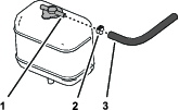
Draining the Oil Cooler
Drain pan capacity: 4 quarts or more.
-
Remove the hose clamp that secures the tank-return hose to the barbed fitting of the hydraulic filter head (Figure 10).
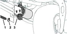
-
Remove the tank-return hose and allow the hydraulic fluid to fully drain from the filter head and hose (Figure 10).
-
Assemble the tank-return hose and hose clamp to the barbed fitting and tighten the clamp (Figure 10).
Removing the Hydraulic Fluid Cooler
-
Remove the 4-blade connector of the machine wire harness from the glow-plug relay (Figure 11).
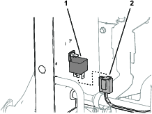
-
Remove the hose clamp that secures the hydraulic cooler-inlet hose to the inlet hydraulic tube, and separate the hose from the tube (Figure 12).
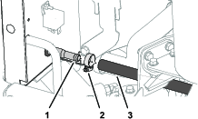
-
Disconnect the hydraulic cooler-outlet tube from the fitting at the top of the hydraulic filter head (Figure 13).
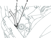
-
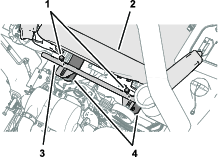
Pull the top of the hydraulic fluid cooler rearward and out of the 2 gripper clips (Figure 14).
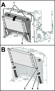
-
Remove the 2 hose clamps that secure the hoses to the barbed fittings at the bottom of the hydraulic fluid cooler (Figure 14).
-
Separate the cooler from the hoses and remove the cooler from the machine (Figure 14).
Removing the Radiator Hoses
-
Remove the hose clamp that secures the lower radiator hose to the outlet of the radiator, and separate the hose from the radiator (Figure 15).
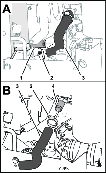
-
Remove the hose clamp that secures the lower radiator hose to the inlet of the engine, and remove the hose from engine (Figure 15).
Retain the hose clamps for installation later. Discard the lower radiator hose.
-
Remove the hose clamp that secures the air-intake hose to the outlet at the top radiator bracket (Figure 16).
Retain the clamp for installation later. You do not need to remove the air-intake hose from the engine air cleaner.
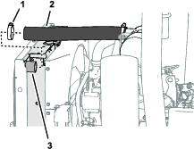
-
Remove the hose clamp that secures the upper radiator hose to the inlet of the radiator, and separate the hose from the radiator (Figure 17).
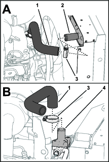
-
Remove the hose clamp that secures the upper radiator hose to the thermostat housing of the engine, and remove the hose from the engine (Figure 17).
Retain the 2 hose clamps for installation later. Discard the upper radiator hose.
Removing the Radiator
Removing the Radiator Shrouds
-
Remove the 4 flange head screws (1/4 x 1/2 inch) that secure the upper fan shroud to the flange of the radiator, and remove the shroud from the machine (Figure 18).
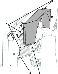
-
Remove the 4 flange head screws (1/4 x 1/2 inch) that secure the lower fan shroud to the flange of the radiator, and remove the shroud from the machine (Figure 19).
Removing the Radiator from the Machine
-
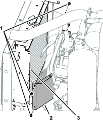
At the forward, lower corner of the radiator, remove the 2 flange capscrews (3/8 x 3/4 inch) that secure the radiator bracket to the rear casting of the machine (Figure 20).
-
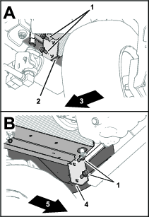
Remove the 2 flange capscrews (3/8 x 3/4 inch) that secure the radiator bracket to the rear casting of the machine at the other side of the machine (Figure 20).
Retain the flange capscrews for installation later.
-
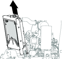
Lift the radiator out of the machine (Figure 21).
Preparing the Radiator
Parts needed for this procedure:
| Radiator/oil cooler | 1 |
| Foam seal | 2 |
| Flange head screw (1/4 x 3/4 inch) | 2 |
| Carriage bolt (5/16 x 3/4 inch) | 4 |
| Serrated-flange nut (5/16 inch) | 4 |
Disassembling the Radiator
-
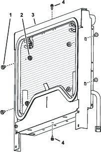
Remove the 2 flange head screws that secure the mounting frame to the radiator (Figure 22).
-
Remove the 4 carriage bolts and 4 serrated-flange nuts that secure the mounting frame to the radiator (Figure 22).
Discard the flange head screws, carriage bolts, and serrated-flange nuts.
-
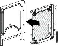
Separate the mounting frame from the radiator (Figure 23).
-
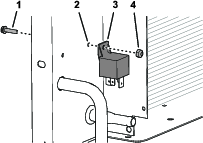
Remove the flange-head screw (#10 x 3/4 inch) and locknut (#10) that secure the glow plug relay to the radiator, and remove the relay (Figure 24).
Retain the mounting frame, screw, locknut, and relay. Discard the radiator and attached hoses, tubes, and clamps.
Replacing the Foam Seals
Assembling the Mounting Frame from the Radiator/Oil Cooler
-
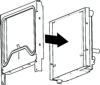
Align the holes in the mounting frame to the holes in the radiator/oil cooler (Figure 26).
-
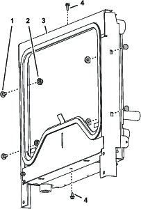
Loosely assemble the mounting frame to the radiator/oil cooler (Figure 27) with the 2 flange head screws (1/4 x 3/4 inch).
-
Assemble the mounting frame to the radiator/oil cooler (Figure 27) with the 4 carriage bolts (5/16 x 3/4 inch) and 4 serrated-flange nuts (5/16 inch).
Tighten the serrated-flange nuts and the flange head screws.
Assembling the Radiator/Oil Cooler to the Machine
Parts needed for this procedure:
| Straight fitting (-8 O-ring face seal / 3/4 inch SAE) | 1 |
| 90° fitting (-8 O-ring face seal / 3/4 inch SAE) | 1 |
| Straight fitting (-8 O-ring face seal / 1-1/16 inch SAE) | 1 |
| Hose—30 cm (11-3/4 inches) | 1 |
Assembling the Radiator Bracket to the Rear Casting
-
At the forward, lower corner of the radiator, loosely assemble the radiator bracket to the rear casting of the machine (Figure 28) with the 2 flange capscrews (3/8 x 3/4 inch) that you removed in Removing the Radiator from the Machine.
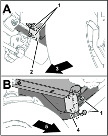
-
At the other side of the machine, loosely assemble the radiator bracket to the rear casting (Figure 28) with the 2 flange capscrews (3/8 x 3/4 inch).
-
Tighten the 4 flange capscrews.
Assembling the Oil Cooler Fittings and Outlet Hose
-
At the forward, lower corner of the radiator, assemble the 90° fitting (-8 O-ring face seal / 3/4 inch SAE) into the oil-cooler outlet as shown in Figure 29, and tighten the fitting nut.
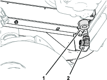
-
Assemble the straight fitting (-8 O-ring face seal / 3/4 inch SAE) into the oil-cooler outlet of the radiator/oil cooler, and tighten the fitting (Figure 30).
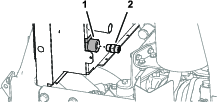
-
Remove the fitting from the top port of the filter head (Figure 31).
Discard the fitting.
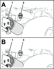
-
Install the straight fitting (-8 O-ring face seal / 1-1/16 inch SAE) into the top port of the filter head (Figure 31).
-
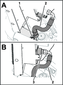
Loosely assemble the straight fitting (Figure 32) of the hose—30 cm (11-3/4 inches) onto the straight fitting that you installed in step 4.
-
Install the 90 fitting (Figure 32) of the hose onto the straight fitting (-8 O-ring face seal / 3/4 inch SAE) that you installed in step 2.
-
Tighten the hose fittings.
Installing the Fan Shrouds, Radiator Hoses, and Oil Cooler Tube
Parts needed for this procedure:
| Bottom fan shroud | 1 |
| Support clamp | 2 |
| Oil-inlet tube | 1 |
| Self-tapping screw (1/4 x 3/4 inch) | 6 |
| Top fan shroud | 1 |
| Flange-head screw (1/4 x 1/2 inch) | 4 |
| Serrated-flange nut (1/4 inch) | 4 |
| Lower radiator hose | 1 |
| Hose clamp | 2 |
| Reservoir bracket | 1 |
| Hose—8 x 254 mm (5/16 x 10 inches) | 1 |
| Small hose clamp | 1 |
| Upper radiator hose | 1 |
Assembling the Fan Shrouds to the Radiator/Oil Cooler
-
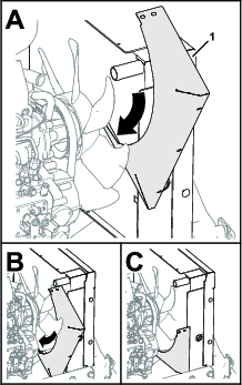
Align the bottom fan shroud to the machine as shown in Figure 33.
-
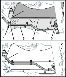
Assemble 2 support clamps to the oil-inlet tube (Figure 34).
-
Thread the swivel nut of the tube onto the 90° fitting (Figure 34).
-
Secure the clamps, tube, and bottom shroud to the radiator/oil cooler (Figure 34) with 3 self-tapping screws (1/4 x 3/4 inch).
-
Tighten the swivel nut of the oil-inlet tube.
-
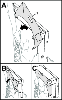
Align the top fan shroud to the machine as shown in Figure 35.
-
Secure the top fan shroud to the radiator/oil cooler (Figure 36) with 3 self-tapping screws (1/4 x 3/4 inch).
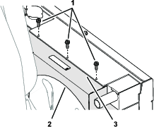
-
At the left side of the machine, assemble the top and bottom fan shrouds (Figure 37) with 2 flange-head screws (1/4 x 1/2 inch) and 2 serrated-flange nuts (1/4 inch).
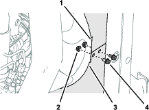
Installing the Lower Radiator Hose
Assembling the Coolant Overflow Hose
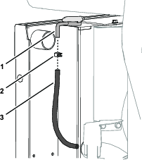
Assemble the hose—8 x 254 mm (5/16 x 10 inches) onto the radiator overflow fitting and secure the hose to the fitting with a small hose clamp (Figure 39).
Assembling the Air-Intake Hose
-
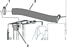
Assemble the free end of the air-intake hose over the outlet at the top of the radiator (Figure 40).
-
Secure the hose to the outlet with the hose clamp (Figure 40) that you removed in Removing the Radiator Hoses.
Assembling the Coolant-Reservoir Bracket to the Fan Shrouds
-
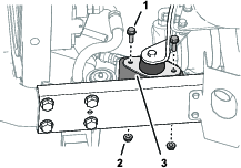
At the right side of the machine, remove the 2 flange-head screws (5/16 x 1 inch) and 2 serrated-flange nuts (5/16 inch) that secure the engine mount to the engine bracket of the frame (Figure 41).
-
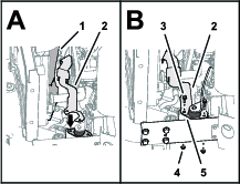
Align the holes in the coolant reservoir bracket with the holes in the top and bottom fan shrouds, and the holes in the engine mount (Figure 42).
-
Loosely assemble the coolant reservoir bracket to the engine mount (Figure 42) with the 2 flange-head screws (5/16 x 1 inch) and 2 serrated-flange nuts (5/16 inch) that you removed in step 1.
-
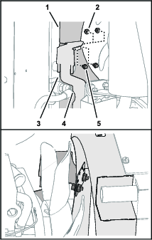
Assemble the top fan shroud, bottom fan shroud, and coolant reservoir bracket (Figure 43) with 2 flange-head screws (1/4 x 1/2 inch) and 2 serrated-flange nuts (1/4 inch).
-
Tighten the flange-head screws (1/4 x 1/2 inch) and (5/16 x 1 inch) and serrated-flange nuts (1/4 inch) and (5/16 inch).
Installing the Upper Radiator Hose
-
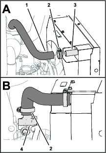
Loosely assemble the upper radiator hose to the inlet of the radiator (Figure 44) with a hose clamp that you removed in Removing the Radiator Hoses.
-
Assemble the other end of the upper radiator hose to the thermostat housing of the engine (Figure 44) with the other hose clamp that you removed in Removing the Radiator Hoses.
-
Tighten the hose clamps.
Replacing the Oil Cooler Return Hose
Parts needed for this procedure:
| Hose 90 cm (35-1/4 inches) | 1 |
| Straight barb fitting | 1 |
| Hose clamp | 2 |
Removing the Oil Cooler Return Hose
Preparing the Oil Cooler Return Hose
Assemble the hose 90 cm (35-1/4 inches) onto the straight barb fitting and secure the hose with a hose clamp (Figure 47).

Installing the Oil Cooler Return Hose
-
At the bottom of the machine, align the oil cooler return hose to the right frame channel as shown in Figure 48.
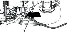
-
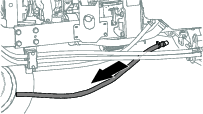
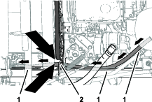
Route the hose along the frame channel toward the control console (Figure 49).
Important: Ensure that the hose routes through the hose guard welded to the frame channel.
-
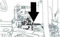
Install the straight barb fitting of the hose into port-T of the reel drive manifold (Figure 50).
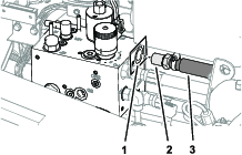
-
Assemble the free end of the oil cooler return hose onto the oil-inlet tube and secure the hose with a hose clamp (Figure 51).
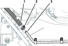
Assembling the Glow-Plug Relay
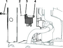
Assemble the glow-plug relay to the radiator with the flange-head screw (#10 x 3/4 inch) and locknut (#10) that you removed in Disassembling the Radiator.
Installing the Coolant Reservoir Tank
Installing the Console Cover and Operator’s Seat
Installing the Console Cover
-
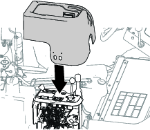
Align the console cover over the control console and lower the cover (Figure 54).
-
Ensure that the magnetic catches of the console secure the cover.
Installing the Operator’s Seat
-
Align the operator's seat over the fuel tank, and tip the seat to access the bottom.
-
Connect the 2-socket connector to the terminals for the seat switch (Figure 56).

-
Tilt the seat down and align the front holes in the seat straps with the holes in the support channel (Figure 57).

-
Assemble the seat straps to the support channel (Figure 57) with the 2 flange-head capscrews that you removed in Removing the Operator’s Seat.
-
At the back of the operator’s seat, align the slots of the heat shield and the holes in the seat straps with the standoff on the cross tube (Figure 58).

-
Secure the heat shield and seat straps to the cross tube with the 2 flange-head capscrews that you removed in Removing the Operator’s Seat.
Adding Coolant and Hydraulic Fluid
Coolant specification: a 50/50 solution of water and permanent ethylene glycol anti-freeze
Coolant capacity: 6.2 L (6-1/2 qt)
Hydraulic fluid specification: refer to the operator’s manual for your machine.
Hydraulic fluid quantity: up to 4 quarts
-
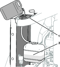
Remove the radiator cap and slowly add the specified coolant until the radiator is full (Figure 59).
-
Install the radiator cap (Figure 59).
-
Remove the cap from the coolant reservoir tank and add the specified coolant until the tank is 1/2 full (Figure 59).
-
Install the cap onto the coolant reservoir tank (Figure 59).
-
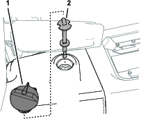
Check the fluid level in the hydraulic tank (Figure 60) and add fluid if needed; refer to the Checking the Hydraulic System procedure in the operator's manual for your machine.
-
Start the engine, allow the engine to warm, and check for coolant and hydraulic fluid leaks.
Repair all leaks.
-
Shut off the engine and remove the key.
Installing the Hood
-
Align the hood over the engine (Figure 61).
-
Insert the pin of the right hood-pivot bracket into the hole in the right hood support, and move the hood right (Figure 61).
-
Align the pin of the left hood-pivot bracket with the hole in the left hood support, and move the hood left (Figure 61).
-
Install the hairpin into the pin of the right hood-pivot bracket (Figure 61).
-
Secure the hood with the 2 latches (Figure 61).
