Safety

Safety and Instructional Decals

Graphic

Safety decals and instructions are easily visible to the operator and are located near any area of potential danger. Replace any decal that is damaged or missing.

decal98-8687
decal106-4669

Setup

The Transpro 80 is intended for use with Greensmaster 800, 1000, 1010, 1600, 1610, 2000, 2600, as well as Flex 18, 21, 1800, 1820, 2100, 2120 and eFlex 1800, 1820, 2100, 2120 Walk Greensmasters.

Mounting the Tongue Assembly

  1. Insert the tongue assembly into the frame assembly while aligning the rear mounting holes (Figure 1).

  2. Secure the tongue assembly into the frame assembly with a clevis pin, 2 washers and 2 cotter pins (Figure 1).

    g215365

Mounting the Axle and Ramp (Model 04245) or Rail (Models 04244 and 04247) Assemblies

Parts needed for this procedure:

Left axle assembly1
Right axle assembly1
Left ramp or rail arm1
Right ramp or rail arm1
Bolts (3/8 x 3 inches)2
Washers4
Nuts (3/8 inch)2
  1. Refer to Figure 2 to determine which mounting holes that you should use to fit the width of your Greensmower.

    g014662

    Important: If your Greensmaster has a groomer attached, it will be mounted differently than above; refer to the following list:

    • Greensmaster 1000/2000 or 2100 with groomer: The left side should be set to position #3 and the right side should be set to #1.

    • Greensmaster 1800/eFlex 1800 with groomer: The left side should be set to position #2 and the right side should be set to #3.

  2. Mount the axle assembly and a ramp assembly (Figure 3) or rail assembly (Figure 4) to each end of the frame with 2 bolts (3/8 x 3 inches), 4 washers and 2 nuts.

    g215364
    g215363

Mounting the Wheel Assemblies

Parts needed for this procedure:

Wheel assembly2
  1. Mount a wheel assembly to each axle hub with 4 lug nuts (Figure 5). Tighten the nuts to 108 N⋅m (80 ft-lbs).

  2. Adjust the tire pressure to 5 psi (34 kPa).

    g014665

    Important: Higher tire pressure may damage the machine.

Mounting and Adjusting the Hitch Straps

The hitch straps are shipped mounted in the standard position (Figure 6).

Important: The trailer tongue must be parallel to the ground when it is aligned with the tow vehicle hitch.

g014666

Using one of the configurations shown in Figure 7 or Figure 8, adjust and secure the hitch straps to the trailer tongue.

g014667
g014668

Mounting the Greensmower Wheel Assemblies

(Models 04244 and 04247 only)

Note: On the Greensmaster 1000, 1010, and 2000 when equipped with a groomer, you must remove the wheel shaft on the groomer end and purchase and install a new wheel shaft (Part No. 106–5385). Also, you must mount the rail assembly on the groomer end to Greensmaster 1600 and 1610 hole locations (Figure 2).

Note: On the Greensmaster 1800, 1820, 2100, and 2120 when equipped with a groomer, you must remove the wheel shaft on the groomer end and purchase and install a new wheel shaft (Part No.136–7287).

  1. Remove the existing standard transport wheels from the wheel shafts on the Greensmower (if equipped).

  2. On the Greensmaster Flex 18 or 21 only, proceed as follows:

    1. Remove the right side drum cover from the machine (Figure 9).

      g017122
    2. Remove and discard the rubber grommet from the axle hole in the drum cover (Figure 9).

    3. Affix the felt seal to the inside of the cover positioning it around the axle hole (Figure 9).

    4. Install the cover to the machine.

  3. Insert a wheel onto each shaft and secure with a wheel clip (Figure 10).

    Note: The Flex 1800, 1820, and 2100, 2120 series requires a different wheel offset than all other Toro Greensmowers. Read and follow the mounting instructions molded into the sides of the wheels.

    g014669

Loading the Trailer

  1. While maintaining control of the trailer bed and holding onto the handle, press down on the latch assembly and the lift handle (Figure 11). Lower the trailer bed to the ground.

    g014670
  2. On flat ramps, pivot the wheel rods upward (Figure 13) and on rail ramps, rotate the wheel rods parallel (open) to the ramp (Figure 14).

  3. Remove the basket from the greens mower, disengage the reel drive and move the throttle to the slowest position. Slowly drive the greens mower onto the trailer until the wheel stops are contacted (Figure 12).

  4. If the rail wheels are not centered on the rails, loosen the fasteners securing the rails to the trailer and adjust the rail position so the rail wheels are centered, then tighten the fasteners.

  5. Shut off the engine and engage the parking brake.

  6. Engage the wheel rods as follows:

    • On flat ramps, rotate the wheel rods downward over the greens mower transport wheels (Figure 13).

    • On rail ramps, lift the wheel rod and rotate it behind the greens mower transport wheels (Figure 14).

      g214902
      g014671
      g014672
  7. Push down on the handle until the trailer assembly locks into the latch assembly (Figure 11).

  8. For Flex GreensMaster machines, secure the front of the machine by hooking the bungee straps to the basket hoop.

    For fixed-head GreensMaster machines, secure the front of the machine by hooking the bungee straps to the basket horns.

  9. Store the basket in the tow vehicle.

Operation

Operating Tips

  1. The Transpro 80 is intended for use with Greensmaster 800, 1000, 1600, 2000, 2600, Flex 18, 21, 1800, 1820, 2100, 2120 and eFlex 1800, 1820, 2100, 2120 Walk Greensmasters. The towing of other products may damage the axles and transmissions that continue to rotate when towed.

  2. Use only a vehicle with the proper tow rating. The Transpro 80 and 1 greens mower weigh approximately 400 lb (182 kg). Ensure that the tow vehicle has adequate braking and handling capacity by checking the recommendations of the vehicle manufacturer.

  3. Ensure that the trailer is properly connected to the tow vehicle before loading or unloading the greens mower to prevent sudden unintended tongue movement or flip up. Use a retention device on the hitch pin to secure the connection.

    Important: The trailer tongue should be parallel to the ground when you align it with the tow vehicle hitch.

  4. During transport, use the bungee strap to secure the greens mower to the trailer (Figure 15). You can move the bungee strap to different mounting holes to accommodate different mowers.

    Note: Secure the bungee strap to the grass basket horns or to the grass basket loop on the eFlex/Flex 1800/2100 models.

    g014673
  5. The Transpro 80 adds extra towing weight to the vehicle. Drive the vehicle safely.

    • Do not drive on highway or public roads.

    • Always slow the tow vehicle when approaching and while making a turn.

    • Always slow the tow vehicle when driving in unfamiliar areas or over rough terrain.

    • Always slow the tow vehicle gradually when changing direction of travel or preparing to stop.

    • When turning or driving on slopes, always slow the tow vehicle, then turn to prevent loss of control and possible upset.

    • Do not make sudden or sharp turns. Do not suddenly change direction of travel on an incline, ramp, grade, slope or similar surface.

    • The maximum towing speed is 15 mph (24 kmh). Always adjust the tow vehicle speed to allow for existing ground conditions, such as wet slick surfaces, loose sand or gravel and/or low visibility conditions, such as dim or bright lighting, fog, mist or rain.

    • Be especially careful when driving a heavily loaded vehicle down an incline or slope. Drive the vehicle up and down the face of the slopes, inclines or grades whenever possible. Do not drive across the face if at all possible. There is a risk of upsetting the vehicle, which can result in serious injury or death.

  6. Before backing up, look to the rear and ensure that no one is behind you. Back up slowly and watch the trailer movement closely.

  7. Use extreme caution and slow speed when backing up the trailer and tow vehicle.

  8. Watch out for traffic when near or crossing roads. Always yield the right of way to pedestrians and other vehicles

  9. If the trailer begins to vibrate abnormally, stop immediately. Shut off the tow vehicle engine. Repair all damage before towing.

  10. Before servicing or making any adjustments to the trailer

    • Stop the tow vehicle and set the parking brake.

    • Shut off the tow vehicle engine and remove the key.

  11. Keep all nuts, bolts and other fasteners tightened securely. Replace any parts removed during servicing or adjustments.

  12. To ensure optimum performance and continued safety of this product, always use genuine Toro replacement parts. Replacement parts and accessories made by other manufacturers may affect the product’s operation, performance or durability. Such use could also void the warranty of The Toro Company.

Maintenance

Recommended Maintenance Schedule(s)

Maintenance Service IntervalMaintenance Procedure
After the first 10 hours
  • Check the torque of the wheel lug nuts.
  • Yearly
  • Service the wheel hub and inspect for damage.
  • Lubricate the wheel hub assembly.
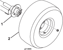
  • Servicing the Wheel Hub

    Maintenance Service IntervalMaintenance Procedure
    Yearly
  • Service the wheel hub and inspect for damage.
    1. Raise the trailer on jack stands.

    2. Remove the 4 lug nuts securing the wheel to the wheel hub and remove the wheel.

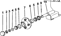
    3. Remove the dust cap from the wheel hub (Figure 16).

    4. Remove the cotter pin and retainer locknut (Figure 16).

    5. Remove the hub nut, spindle washer and hub assembly from the axle (Figure 16).

    6. Inspect all of the hub assembly parts, including the bearings, bearing cups, and oil seal. Replace any damaged parts.

      g265352

    Lubricating the Wheel Hub Assembly

    Maintenance Service IntervalMaintenance Procedure
    Yearly
  • Lubricate the wheel hub assembly.
    1. Wipe away the existing grease from the bearings, bearing cups, and hub assembly with a clean, dry rag.

    2. Pack the bearing cups and interior surfaces of the hub assembly with high-temperature grease so that the bearings roller faces are completely coated.

    3. Install the bearing cups and bearings to the hub assembly as shown in Figure 16.

    4. Clean up any excess grease from the outside of the hub assembly.

    Installing the Wheel Hub Assembly

    1. Install the oil seal, hub assembly, and spindle washer as shown in Figure 16.

    2. Tighten the hub nut while turning the wheel hub assembly to seat the bearings and remove all end play.

    3. While turning the wheel hub assembly, torque the hub nut to 8.5 to 20.3 N⋅m (75 to 180 in-lbs).

    4. Loosen the hub nut until it does not contact the washer and the hub has end play.

    5. Tighten the hub nut to 1.7 to 2.3 N⋅m (15 to 20 in-lbs) while rotating the hub.

    6. Place the retainer locknut over the hub nut so that the cotter pin hole is aligned with a slot on the retainer locknut.

    7. Install a new cotter pin through the slot in the retainer locknut and the axle and bend both legs to secure the pin.

    8. Secure the hub cap.

    Checking the Torque of the Wheel Lug Nuts

    Maintenance Service IntervalMaintenance Procedure
    After the first 10 hours
  • Check the torque of the wheel lug nuts.
  • Check the torque of the wheel lug nuts each time you install the wheels and after the first 10 hours of operation.

    Warning

    Failure to maintain proper torque could result in failure or loss of wheel and could result in personal injury.

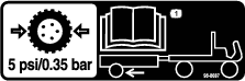
    Torque wheel lug nuts to 108 N⋅m (80 ft-lbs).