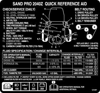
| Maintenance Service Interval | Maintenance Procedure |
|---|---|
| Before each use or daily |
|
Introduction
This machine is a ride-on piece of utility equipment intended to be used by professional, hired operators in commercial applications. It is primarily designed for conditioning sand traps on well-maintained golf courses and commercial grounds.
Read this information carefully to learn how to operate and maintain your product properly and to avoid injury and product damage. You are responsible for operating the product properly and safely.
Visit www.Exmark.com for product safety and operation training materials, accessory information, help finding a dealer, or to register your product.
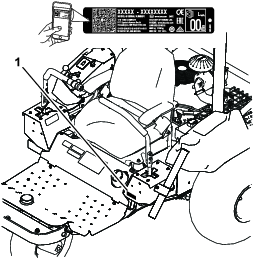
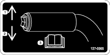
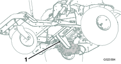
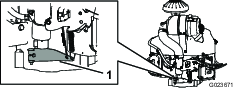
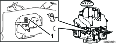
Whenever you need service, genuine Toro parts, or additional information, contact an Authorized Service Dealer or Toro Customer Service and have the model and serial numbers of your product ready. Figure 1 identifies the location of the model and serial numbers on the product. Write the numbers in the space provided.
Important: With your mobile device, you can scan the QR code (if equipped) on the serial number plate to access warranty, parts, and other product information.
This manual identifies potential hazards and has safety messages identified by the safety-alert symbol (Figure 2), which signals a hazard that may cause serious injury or death if you do not follow the recommended precautions.

This manual uses 2 words to highlight information. Important calls attention to special mechanical information and Note emphasizes general information worthy of special attention.
This product complies with all relevant European directives; for details, please see the separate product specific Declaration of Conformity (DOC) sheet.
It is a violation of California Public Resource Code Section 4442 or 4443 to use or operate the engine on any forest-covered, brush-covered, or grass-covered land unless the engine is equipped with a spark arrester, as defined in Section 4442, maintained in effective working order or the engine is constructed, equipped, and maintained for the prevention of fire.
Because in some areas there are local, state, or federal regulations requiring that a spark arrester be used on the engine of this machine, a spark arrester is available as an option. If you require a spark arrester, contact your Authorized Toro Service Dealer.
The enclosed engine owner's manual is supplied for information regarding the US Environmental Protection Agency (EPA) and the California Emission Control Regulation of emission systems, maintenance, and warranty. Replacements may be ordered through the engine manufacturer.
Warning
CALIFORNIA
Proposition 65 Warning
The engine exhaust from this product contains chemicals known to the State of California to cause cancer, birth defects, or other reproductive harm.
Battery posts, terminals, and related accessories contain lead and lead compounds, chemicals known to the State of California to cause cancer and reproductive harm. Wash hands after handling.
Use of this product may cause exposure to chemicals known to the State of California to cause cancer, birth defects, or other reproductive harm.
Safety
This machine has been designed in accordance with Directive 2006/42/EC and ANSI B71.4-2017. However, when you install attachments on the machine, you must add additional weight to the machine, as specified, to comply to the standards.
General Safety
This product is capable of causing personal injury. Always follow all safety instructions to avoid serious personal injury.
Using this product for purposes other than its intended use could prove dangerous to you and bystanders.
-
Read and understand the contents of this Operator’s Manual before starting the engine. Ensure that everyone using this product knows how to use it and understands the warnings.
-
Do not put your hands or feet near moving components of the machine.
-
Use your full attention while operating the machine. Do not engage in any activity that causes distractions; otherwise, injury or property damage may occur.
-
Do not operate the machine without all guards and other safety protective devices in place and working on the machine.
-
Keep the machine a safe distance away from bystanders while it is moving.
-
Keep children out of the operating area. Never allow children to operate the machine.
-
Stop the machine and shut off the engine before servicing or fueling the machine.
Improperly using or maintaining this machine can result in injury.
To reduce the potential for injury, comply with these safety instructions
and always pay attention to the safety-alert symbol  , which means
Caution, Warning, or Danger—personal safety instruction. Failure
to comply with these instructions may result in personal injury or
death.
, which means
Caution, Warning, or Danger—personal safety instruction. Failure
to comply with these instructions may result in personal injury or
death.
You can find additional safety information where needed throughout this manual.
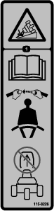
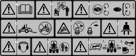
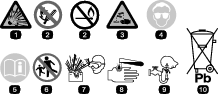
Safety and Instructional Decals
|
Safety decals and instructions are easily visible to the operator and are located near any area of potential danger. Replace any decal that is damaged or missing. |


Setup
Note: Determine the left and right sides of the machine from the normal operating position.
Note: Remove and discard all the shipping brackets and fasteners.
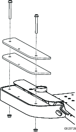
Removing the Shipping Board
Warning
If you drive the machine without the shipping board or an attachment installed, the machine can tip over and injure someone or damage property.
Drive the machine only if the shipping board or an approved attachment is installed.
Before you can install an attachment on the machine, you must remove the shipping board.
-
Park the machine on a level surface, move the control handles to the neutral-locked position, engage the parking brake, shut off the engine, and remove the key.
-
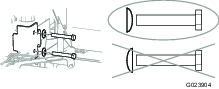
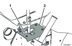
Remove the nuts, bolts, and washers securing the shipping board to the rear of the machine (Figure 3).
-
Discard the fasteners and the shipping board.
Installing an Attachment
Parts needed for this procedure:
| Attachment and related parts (sold separately) | – |
Warning
If you drive the machine without an attachment installed, it can tip over and injure someone or damage property.
Drive the machine only if there is an approved attachment installed.
Park the machine on a level surface, move the control handles to the neutral-locked position, engage the parking brake, shut off the engine, and remove the key.
Refer to the attachment Installation Instructions for information on installing the attachment.
Installing the Front Weights
Parts needed for this procedure:
| Front weights (as needed per attachment) | – |
This machine has been designed in accordance with 2006/42/EC and ANSI B71.4-2012.
However, when you install attachments on the machine, you must add additional weight to the machine, as specified, to comply to the standards.
Use the chart below to determine the additional weight required. The machine comes with 4 weights. Each attachment comes with the necessary additional weights, if required.
| Attachment | Number of weights required |
|---|---|
| Flex tooth rake | 4 |
| Flex tooth rake with finish brush | 6 |
| Nail drag | 6 |
| Nail drag with finish drag mat | 8 |
Refer to Installing and Removing the Weights.
Connecting the Battery
Parts needed for this procedure:
| Bolt (5/16 x 3/4 inch) | 1 |
| Nut (5/16 inch) | 2 |
-
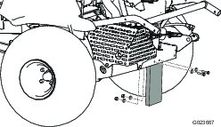
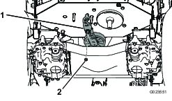
Cut the cable tie securing the battery cables to the frame, and discard the cable tie (Figure 4).
-
Remove the red plastic cover from the positive battery terminal (Figure 5).
-
Slide the red boot away from the end of the positive battery cable, and use a bolt (5/16 x 3/4 inch) and a nut (5/16 inch) to mount the positive cable to the positive battery terminal.
-
Slide the red boot over the terminal and the fasteners.
-
Remove the black plastic cover from the negative battery terminal.
-
Use a bolt (5/16 x 3/4 inch) and a nut (5/16 inch) to mount the negative cable to the negative battery terminal.
Applying the CE Service Decal (CE Only)
Parts needed for this procedure:
| Service decal (130-2620) | 1 |
If this machine must be CE compliant (Europe), apply the CE service decal (130-2620) over the existing service decal (127–0371).
Installing the Roll Bar
Parts needed for this procedure:
| Roll bar | 1 |
| Bolt | 4 |
| Flange locknut | 4 |
| Spring washer | 4 |
| Bracket | 2 |
-
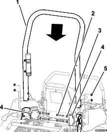
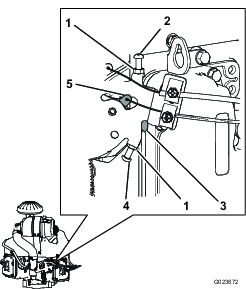
Remove the roll bar from the crate.
-
Place the roll bar on the machine as shown in Figure 6.
-
Install the brackets on the frame of the machine.
Important: Ensure that the throttle cable and the choke cable are out of the way, so that they do not get pinched by the roll bar or a bracket.
-
Align the holes in the brackets, the roll bar, and the frame.
-
Install a bolt, with a spring washer, through each hole.
Important: Ensure that each spring washer is positioned so that the convex side faces the bolt head as shown in Figure 7.
-
Install a flange locknut on each bolt, and torque each of them to 102 N∙m (75 ft-lb).
Product Overview
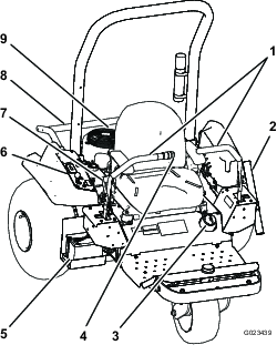
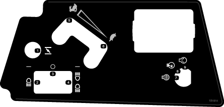
Control Handles
Use the control handles (Figure 8) to drive the machine forward and backward, and to turn in either direction.
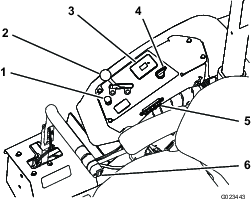
Ignition Switch
The ignition switch (Figure 9), used to start and shut off the engine, has 3 positions: OFF, RUN, and START. Rotate the key clockwise to the START position to start the engine. Release the key when the engine starts. The key will move automatically to the RUN position. To shut off the engine, rotate the key counterclockwise to the OFF position.
Choke Control
To start a cold engine, close the carburetor choke by pulling the choke control (Figure 9) up to the CLOSED position. After the engine starts, regulate the choke to keep the engine running smoothly. As soon as possible, open the choke by pushing the control down to the OPEN position.
Note: A warm engine requires little or no choking.
Throttle Lever
The throttle lever (Figure 9) controls the speed of the engine. Moving the throttle lever forward toward the FAST position increases the engine speed. Moving it backward toward the SLOW position decreases the engine speed.
Note: The throttle lever cannot shut off the engine.
Attachment Switch
To raise the attachment, press the upper part of the attachment switch (Figure 10); to lower the attachment, press the lower part of the attachment switch.
Note: The machine has a double-acting lift cylinder. You can apply down pressure to the attachment for certain operating conditions.
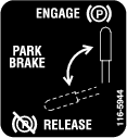
Parking Brake
To engage the parking brake (Figure 8), pull back on the lever of the parking brake. To disengage it, push the lever forward.
Hour Meter
The hour meter (Figure 9) indicates the total hours of machine operation. The hour meter runs whenever the ignition switch is in the ON position, as long as the battery is fully charged (13.8 V or more) or you are sitting in the seat, thereby activating the seat switch.
An optional wireless hour meter is available through your Authorized Toro Distributor. To install it, refer to Installing a Wireless Hour Meter.
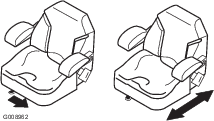
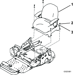
Seat-Adjustment Lever
While sitting on the seat, move the lever in front of the seat (Figure 11) to the left, and slide the seat to the desired position. Release the lever to lock the seat into position.
Note: Specifications and design are subject to change without notice.
| Machine only | With flex tooth rake | With nail drag | With nail drag and finish mat | |
|---|---|---|---|---|
| Weight | 399 kg (880 lb)* | 417 kg (920 lb)** | 439 kg (970 lb)** | 445 kg (980 lb)** |
| Width | 147 cm (58 inches) | 213 cm (84 inches) | 182 cm (71.5 inches) | 198 cm (78 inches) |
| Length | 186 cm (73.3 inches) | 226 cm (89.0 inches) | 215 cm (84.8 inches) | 297 cm (117 inches) |
| Height | 185 cm (73 inches) | |||
| Wheelbase | 147 cm (58 inches) | |||
* with 4 weights, empty fuel tank, and no operator
** with the attachment and weights, empty fuel tank, and no operator
Attachments/Accessories
A selection of Toro approved attachments and accessories is available for use with the machine to enhance and expand its capabilities. Contact your Authorized Service Dealer or Distributor or go to www.Exmark.com for a list of all approved attachments and accessories.
To best protect your investment and maintain optimal performance of your Toro equipment, count on Toro genuine parts. When it comes to reliability, Toro delivers replacement parts designed to the exact engineering specification of our equipment. For peace of mind, insist on Toro genuine parts.
Operation
Note: Determine the left and right sides of the machine from the normal operating position.
Before Operation
Before Operation Safety
General Safety
-
Never allow children or untrained people to operate or service the machine. Local regulations may restrict the age of the operator. The owner is responsible for training all operators and mechanics.
-
Become familiar with the safe operation of the equipment, operator controls, and safety signs.
-
Park the machine on a level surface; engage the parking brake, shut off the engine, remove the key, and wait for all movement to stop before leaving the machine.
-
Know how to stop the machine and engine quickly.
-
Check that operator-presence controls, safety switches, and shields are attached and functioning properly. Do not operate the machine unless they are functioning properly.
-
Before operating, always inspect the machine to ensure that the components and fasteners are in good working condition. Replace worn or damaged components and fasteners.
Fuel Safety
-
Use extreme care in handling fuel. It is flammable and its vapors are explosive.
-
Extinguish all cigarettes, cigars, pipes, and other sources of ignition.
-
Use only an approved fuel container.
-
Do not remove the fuel cap or fill the fuel tank while the engine is running or hot.
-
Do not add or drain the fuel in an enclosed space.
-
Do not store the machine or fuel container where there is an open flame, spark, or pilot light, such as on a water heater or other appliance.
-
If you spill fuel, do not attempt to start the engine; avoid creating any source of ignition until the fuel vapors have dissipated.
Breaking in the Machine
New engines take time to develop full power. Drive systems have more friction when they are new, placing additional load on the engine.
Allow the first 8 hours of operating time for the break-in period.
Since the first hours of operation are critical to future dependability of the machine, monitor the functions and performance closely so that you can notice and correct minor difficulties, which could lead to major problems. Inspect the machine frequently during the break-in period, for signs of oil leakage, loose fasteners, or any other malfunction.
Installing and Removing the Weights
The machine complies with the ANSI B71.4-2012 standards at the time of production. However, when the following attachments are installed on the machine, additional weight is required to comply to the standards. Use the chart below to determine the additional weight required. The machine comes with 4 weights. Each attachment comes with the necessary additional weights, if required.
| Attachment | Number of weights required |
|---|---|
| Flex tooth rake | 4 |
| Flex tooth rake with finish brush | 6 |
| Nail drag | 6 |
| Nail drag with finish drag mat | 8 |
-
Remove the 2 bolts and 2 nuts securing the existing weights on the front of the machine (Figure 12).
Note: If the machine is equipped with the light kit, remove the nut and the bolt securing the front light to the machine. Retain all of the parts; refer to the Light Kit Installation Instructions.
-
Add or remove weights as necessary.
-
Secure the weights with the 2 bolts and the 2 nuts.
-
For most of the attachments, use the existing bolts.
-
The finish drag mat includes 2 longer bolts to accommodate the additional weights that it requires.
Note: If the machine is equipped with the light kit, install the front light by inserting the bolt through the weights and securing it with the nut; refer to the Light Kit Installation Instructions.
-
Checking the Level of the Engine Oil
Toro Premium Engine Oil is available from your Authorized Toro Distributor.
Crankcase Capacity: 1.8 L (1.7 US qt) with filter change
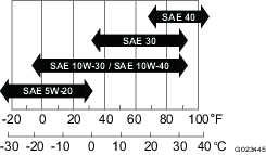
Use 4-cycle engine oil that meets or exceeds the following requirements:
-
API service category: SJ, SL, SM, or higher
-
Viscosity: SAE 30; refer to the following chart for other viscosities (Figure 13):
Important: Using multi-viscosity oils, such as 10W-30, increases oil consumption. Check the oil level more frequently when using them.
-
Park the machine on a level surface, lower the attachment, move the control handles to the neutral-locked position, engage the parking brake, shut off the engine, and remove the key.
-
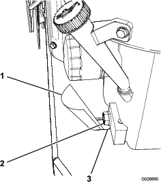
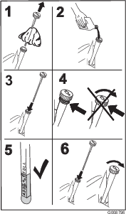
Remove the dipstick (Figure 14) and wipe it with a clean cloth (Figure 15).
-
Insert the dipstick into the fill tube without threading it into the port.
-
Remove the dipstick from the tube and check the oil level. If the oil level is low, slowly pour only enough oil into the fill tube to raise the oil level to the upper-limit mark on the dipstick
Important: Keep the engine oil level between the upper and lower limits on the dipstick. Engine failure may occur as a result of running the engine with too much or too little engine oil.
-
Install the dipstick firmly in place.
Important: The dipstick must be fully seated in the tube to provide proper sealing of the engine crankcase. Failure to seal the crankcase may result in engine damage.
Filling the Fuel Tank
Fuel tank capacity: 17 L (4.5 US gallons)
Recommended Fuel:
-
For best results, use only clean, fresh (less than 30 days old), unleaded gasoline with an octane rating of 87 or higher ((R+M)/2 rating method).
-
Ethanol: Gasoline with up to 10% ethanol (gasohol) or 15% MTBE (methyl tertiary butyl ether) by volume is acceptable. Ethanol and MTBE are not the same. Gasoline with 15% ethanol (E15) by volume is not approved for use. Never use gasoline that contains more than 10% ethanol by volume, such as E15 (contains 15% ethanol), E20 (contains 20% ethanol), or E85 (contains 85% ethanol). Using unapproved gasoline may cause performance problems and/or engine damage which may not be covered under warranty.
-
Do not use gasoline containing methanol.
-
Do not store fuel either in the fuel tank or fuel containers over the winter unless a fuel stabilizer is used.
-
Do not add oil to gasoline.
-
Park the machine on a level surface, lower the attachment, move the control handles to the neutral-locked position, engage the parking brake, shut off the engine, and remove the key.
-
Clean the area around the fuel-tank cap (Figure 16).
-
Remove the fuel-tank cap.
-
Fill the tank to about 25 mm (1 inch) below the top of the tank (bottom of the filler neck). Do not overfill.
-
Install the cap.
-
Wipe up any fuel that may have spilled, to prevent a fire hazard.
Checking the Level of the Hydraulic Fluid
| Maintenance Service Interval | Maintenance Procedure |
|---|---|
| Before each use or daily |
|
Important: For accuracy, check the level of the hydraulic fluid only when the engine and the hydraulic system are cold.
The reservoirs of the machine are filled at the factory with high-quality hydraulic fluid. The best time to check the hydraulic fluid is when the fluid is cold. The machine should be in the transport configuration. If the fluid level is below the top of the horizontal part of the cut-out sight window on the rear of the hydraulic reservoirs (Figure 17), add fluid to bring the fluid to the acceptable level. Do not overfill the reservoirs. If the fluid level is at the top of the horizontal part of the sight window, no fluid addition is required. The recommended replacement fluid is:
Fluid Type: Toro Premium Transmission/Hydraulic Tractor Fluid or Mobilfluid® 424
Capacity:
-
Left side—1.9 L (2.0 US qt)
-
Right side—2.0 L (2.1 US qt)
Alternative fluids: If the specified fluid is not available, other universal tractor hydraulic fluids (UTHF) may be used, but they must be only conventional, petroleum-based products, not synthetics or biodegradable fluids. The specifications must fall within the listed range for all of the following material properties and the fluid should meet listed industry standards. Check with your fluid supplier to see if the fluid meets these specifications.
Note: Toro will not assume responsibility for damage caused by improper substitutions, so use only products from reputable manufacturers who will stand behind their recommendation.
| Material Properties: | |
| Viscosity, ASTM D445 | cSt @ 40°C (104°F) 55 to 62 |
| Viscosity Index ASTM D2270 | 140 to 152 |
| Pour Point, ASTM D97 | -37°C to -43°C (-35°F to -46°F) |
| Industry Specifications: API GL-4, AGCO Powerfluid 821 XL, Ford New Holland FNHA-2-C-201.00, Kubota UDT, John Deere J20C, Vickers 35VQ25, and Volvo WB-101/BM | |
Note: Many hydraulic fluids are almost colorless, making it difficult to spot leaks. A red dye additive for the hydraulic fluid is available in 20 ml (2/3 fl oz) bottles. One bottle is sufficient for 15 to 22 L (4 to 6 US gallons) of hydraulic fluid. Order part number 44-2500 from your Authorized Toro Distributor.
-
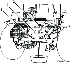
Park the machine on a level surface, lower the attachment, engage the parking brake, shut off the engine, and remove the key.
-
Look at the opening in each of the fluid-reservoir brackets, and check the level of the hydraulic fluid.
Note: The fluid level should be at the bottom of each of the openings, as shown in Figure 17.
-
If the fluid level is low in either of the reservoirs, add fluid as follows:
-
Clean the area around the fluid-reservoir caps to prevent debris from entering the system (Figure 17).
-
Remove the caps from the reservoirs.
-
Slowly fill the reservoir with the appropriate hydraulic fluid until the level reaches the bottom of the openings in the brackets.
Important: To prevent system contamination, clean the top of the fluid container before opening it. Ensure that the pour spout and the funnel are clean.
Important: Do not overfill the reservoirs.
-
Install the reservoir caps.
-
Checking the Tire Pressure
| Maintenance Service Interval | Maintenance Procedure |
|---|---|
| Before each use or daily |
|
Park the machine on a level surface, lower the attachment, engage the parking brake, shut off the engine, and remove the key.
Check the tire pressure before operating the machine (Figure 18).
Pressure: 48 kPa (7 psi)
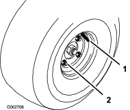
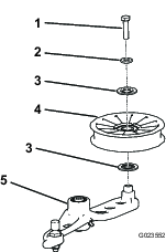
Torquing the Wheel Lug Nuts
| Maintenance Service Interval | Maintenance Procedure |
|---|---|
| After the first 8 hours |
|
| Every 100 hours |
|
Park the machine on a level surface, lower the attachment, engage the parking brake, shut off the engine, and remove the key.
Torque the lugs nuts (Figure 18) to 61 to 75 N∙m (45 to 55 ft-lb).
During Operation
During Operation Safety
General Safety
-
The owner/operator can prevent and is responsible for accidents that may cause personal injury or property damage.
-
Wear appropriate clothing, including eye protection; long pants; substantial, slip-resistant footwear; and hearing protection. Tie back long hair and do not wear loose clothing or loose jewelry.
-
Use your full attention while operating the machine. Do not engage in any activity that causes distractions; otherwise, injury or property damage may occur.
-
Do not operate the machine while ill, tired, or under the influence of alcohol or drugs.
-
Never carry passengers on the machine and keep bystanders and pets away from the machine during operation.
-
Operate the machine only in good visibility to avoid holes or hidden hazards.
-
Before you start the engine, ensure that all drives are in neutral, the parking brake is engaged, and you are in the operating position.
-
Look behind and down before backing up to be sure of a clear path.
-
Use care when approaching blind corners, shrubs, trees, or other objects that may obscure your vision.
-
Stop the machine and inspect the attachment after striking an object or if there is an abnormal vibration in the machine. Make all necessary repairs before resuming operation.
-
Slow down and use caution when making turns and crossing roads and sidewalks with the machine. Always yield the right-of-way.
-
Never run an engine in an area where exhaust gasses are enclosed.
-
Never leave a running machine unattended.
-
Before leaving the operating position, do the following:
-
Park the machine on level ground.
-
Lower the attachments.
-
Engage the parking brake.
-
Shut off the engine and remove the key.
-
Wait for all moving parts to stop.
-
-
Do not operate the machine when there is the risk of lightning.
-
Do not use the machine as a towing vehicle.
-
When necessary, wet surfaces prior to conditioning to minimize dust creation.
-
Use accessories, attachments, and replacement parts approved by The Toro® Company only.
Rollover Protection System (ROPS) Safety
-
Do not remove the ROPS from the machine.
-
Ensure that the seat belt is attached and that you can release it quickly in an emergency.
-
Check carefully for overhead obstructions and do not contact them.
-
Keep the ROPS in safe operating condition by thoroughly inspecting it periodically for damage and keeping all the mounting fasteners tight.
-
Replace a damaged ROPS. Do not repair or alter it.
-
The ROPS is an integral safety device.
-
Always wear your seat belt.
Slope Safety
-
Establish your own procedures and rules for operating on slopes. These procedures must include surveying the site to determine which slopes are safe for machine operation. Always use common sense and good judgment when performing this survey.
-
Slopes are a major factor related to loss of control and rollover accidents, which can result in severe injury or death. The operator is responsible for safe slope operation. Operating the machine on any slope requires extra caution.
-
Slopes are a major factor related to loss-of-control and tip-over accidents, which can result in severe injury or death. Operating the machine on any slope requires extra caution.
-
Operate the machine at a lower speed when you are on a slope.
-
If you feel uneasy operating the machine on a slope, do not do it.
-
Watch for holes, ruts, bumps, rocks, or other hidden objects. Uneven terrain could overturn the machine. Tall grass can hide obstacles.
-
Choose a low ground speed so you will not have to stop or shift while on a slope.
-
A rollover can occur before the tires lose traction.
-
Avoid operating the machine on wet grass. Tires may lose traction; regardless if the brakes are available and functioning.
-
Avoid starting, stopping, or turning the machine on a slope.
-
Keep all movement on slopes slow and gradual. Do not suddenly change the speed or direction of the machine.
-
Do not operate the machine near drop-offs, ditches, embankments, or bodies of water. The machine could suddenly roll over if a wheel goes over the edge or the edge caves in. Establish a safety area between the machine and any hazard (2 machine widths).
Starting and Shutting Off the Engine
-
Move the control handles to the neutral-locked position (Figure 19).
-
Engage the parking brake; refer to Engaging the Parking Brake.
-
Pull the choke control upward to the ON position (when starting a cold engine), and move the throttle lever to the SLOW position.
Important: When operating the machine in temperatures less than 0°C (32°F) allow the machine time to warm up before using it. This prevents damage to the hydraulic system.
-
Insert the key into the ignition switch and rotate it clockwise to start the engine. Release the key when the engine starts. Regulate the choke to keep the engine running smoothly.
Important: To prevent overheating of the starter motor, do not keep the ignition key in the START position for longer than 10 seconds. After 10 seconds of continuous cranking, wait 60 seconds before using the starter motor again.
-
To shut off the engine, move the throttle control to the SLOW position, and turn the key to the OFF position. Remove the key from the switch to prevent accidental starting.
Note: In an emergency, simply turn the key to the OFF position.
Using the Parking Brake
Always engage the parking brake when you stop the machine or leave it unattended.
Engaging the Parking Brake
Warning
The parking brake may not hold the machine parked on a slope and could cause personal injury or property damage.
Do not park on slopes unless the wheels are chocked or blocked.
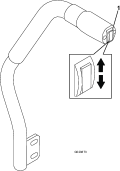
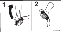
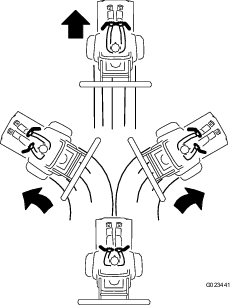
To engage the parking brake, pull upward on the handle (Figure 20).
Disengaging the Parking Brake
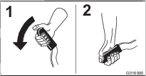
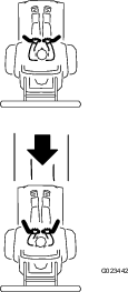
To disengage the parking brake, push downward on the handle (Figure 21).
Using the Safety Interlock System
Caution
If the safety interlock switches are disconnected or damaged, the machine could operate unexpectedly, causing personal injury.
-
Do not tamper with the interlock switches.
-
Check the operation of the interlock switches daily, and replace any damaged switches before operating the machine.
The safety interlock system is designed to prevent the engine from starting unless:
-
The parking brake is engaged.
-
The control handles are in the neutral-locked position
The safety interlock system also stops the engine when you move the control handles out of the neutral-locked position while you are out of the seat or while the parking brake is set.
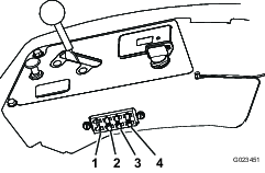
The hour meter has symbols to notify you when the interlock component is in the correct position. When the component is in the correct position, a triangle appears in the corresponding location (Figure 22).
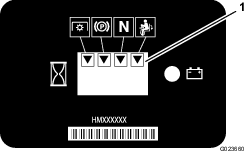
Note: The PTO (power take-off) interlock is not used on this machine.
Testing the Safety Interlock System
| Maintenance Service Interval | Maintenance Procedure |
|---|---|
| Before each use or daily |
|
If the safety interlock system does not operate as described below, have an Authorized Toro Distributor repair it immediately.
-
Sit on the seat, move the control handles to the neutral position, and engage the parking brake.
-
Start the engine.
-
Get off the seat and slowly move each control handle forward and backward.
The engine should shut off in 1 to 3 seconds after moving either control handle in either direction. If it does not, correct the problem. Repeat steps 2 and 3 for the other control handle.
-
Sitting on the seat, engage the parking brake. Move either control handle out of the neutral-locked position. Try starting the engine; the engine should not crank. Repeat this step for the other control handle.
Driving the Machine
Caution
Operating the machine demands attention to prevent tipping or loss of control.
-
Use care when entering and leaving sand traps.
-
Use extreme caution around ditches, creeks, or other hazards.
-
Use caution when operating the machine on a steep slope.
-
Reduce your speed when making sharp turns or when turning on hillsides.
-
Avoid sudden stops and starts.
-
Do not go from reverse to full forward without first coming to a complete stop.
Caution
The machine can spin very rapidly. If you misuse the control handles, you may lose control of the machine and injure someone or damage the machine or other property.
-
Use caution when making turns.
-
Slow the machine down before making sharp turns.
Using the Control Handles
Driving the Machine Forward
Note: The engine shuts off if you move the control handles while the parking brake is engaged.
-
Disengage the parking brake; refer to Disengaging the Parking Brake.
-
Move the control handles to the center, unlocked position.
-
To go forward, slowly push the control handles forward (Figure 24).
To stop the machine, move the control handles to the neutral position.
Driving the Machine Backward
-
Ensure that the attachment is in the desired position.
-
Move the control handles to the center, unlocked position.
-
To go backward, look behind and slowly pull the control handles backward (Figure 25).
Raking a Sand Trap
Read this entire section on raking before raking a sand trap. There are many conditions that determine the adjustments necessary. The texture and depth of the sand, moisture content, weeds, and the amount of compaction are all factors that can vary from course to course, or even from trap to trap on the same course. Make the adjustments on the rake for optimum results in your particular area.
Learning How to Rake
Practice raking in a large and level trap on the course. Practice starting and stopping, turning, raising and lowering the rake, entering and leaving the trap, etc. Practice at a moderate engine speed and a slow ground speed. This training helps the operator to gain confidence in the performance of the machine.
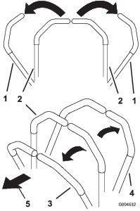
The recommended pattern for raking a trap is shown in Figure 26. This pattern avoids unnecessary overlap, keeps compaction to a minimum, and leaves a neat, attractive pattern on the sand. This is the most efficient raking method, however, it is important to vary the raking pattern regularly to reduce the chance of creating a washboard effect.
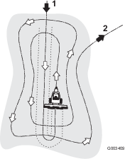
Enter the trap straight into the long dimension, where the bank is the least steep. Drive through the center of the trap almost to the end, turn to either direction as sharp as you can, and come back right next to the first pass. Spiral outward as shown in Figure 26, and leave the trap at a right angle in a level area.
Leave steep, short banks and small pockets for touch-up with a hand rake.
Raking Tips
-
If the sand is deep enough, you can rake right up to the edge of the trap in level areas.
-
If the sand feathers out to the turf, stay far enough away from the edge to avoid disturbing the underlying soil.
-
Do not rake too close to a short, steep bank. The sand will merely flow down into the bottom of the trap.
-
Some touch-up with a hand rake may be necessary on steep banks, small pockets, etc.
Entering and Leaving the Trap
When entering the trap, do not lower the rake until it is over the sand. This avoids cutting the turf or dragging grass clippings or other debris into the trap. Lower the rake while the machine is moving.
When leaving the trap, start raising the rake when the front wheel leaves the trap. As the machine moves out, the rake will be lifting and will not drag sand out onto the grass.
Through experience and practice, the operator will soon understand the required timing for entering and leaving the trap properly.
After Operation
After Operation Safety
-
Clean grass and debris from the muffler and engine compartment to help prevent fires. Clean up oil or fuel spills.
-
Park the machine on a level surface; engage the parking brake; shut off the engine; remove the key; and wait for all movement to stop before leaving the machine.
-
Allow the engine to cool before storing the machine in any enclosure.
-
Shut off the fuel before storing or transporting the machine.
-
Never store the machine or fuel container where there is an open flame, spark, or pilot light, such as on a water heater or on other appliances.
-
Keep all parts of the machine in good working condition and all hardware tightened.
-
Maintain and clean the seat belt(s) as necessary.
-
Replace all worn or damaged decals.
Pushing or Towing the Machine
Warning
The engine and hydrostatic transmissions can become very hot and cause severe burns.
Allow the engine and hydrostatic transmissions to cool completely before accessing the bypass-valve levers.
Important: Do not tow the machine for long distances or at high speeds. Doing so could damage the machine. You can tow the machine slowly from the grooming surface to the on-site trailer.
The bypass-valve levers are located on the top of each hydrostatic transmission.
Important: Ensure that the bypass-valve levers are in the fully forward position when operating the machine, or severe damage to the hydraulic system can occur.
-
Park the machine on a level surface, lower the attachment, move the control handles to the neutral-locked position, engage the parking brake, shut off the engine, and remove the key.
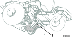
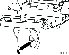
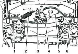
-
From underneath the machine, rotate the bypass-valve levers (Figure 27 and Figure 28) so that they point inward, toward the center of the machine (Figure 29), and disengage the parking brake; refer to Using the Parking Brake.
Note: This allows the hydraulic fluid to bypass the pumps, enabling the wheels to turn freely.
-
When you are finished pushing or towing the machine, rotate the bypass-valve levers so that they point toward the front of the machine, to allow the machine to drive (Figure 29).
Transporting the Machine
Warning
Driving on the street or roadway without turn signals, lights, reflective markings, or a slow-moving-vehicle emblem is dangerous and can lead to accidents causing personal injury.
Do not drive the machine on a public street or roadway.
-
If you are using a trailer, connect it to the towing vehicle and connect the safety chains.
-
If applicable, connect the trailer brakes.
-
Load the machine onto the trailer or truck.
-
Move the control handles to the neutral-locked position, engage the parking brake, shut off the engine, and remove the key.
-
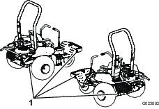
Use the tie-down points on the machine (Figure 30) to securely fasten the machine to the transport vehicle with straps, chains, cable, or ropes.
Loading the Machine
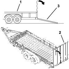
Use extreme caution when loading or unloading the machine onto a trailer or a truck. Use a full-width ramp that is wider than the machine for this procedure.
Important: Do not use narrow individual ramps for each side of the machine.
The trailer or truck and ramp should be as level as possible when loading the machine to avoid getting the attachment caught as the machine moves from the ground to the ramp.
If you are loading the machine on or near a slope, position the trailer or truck so that it is on the down side of the slope and the ramp extends up the slope; this minimizes the ramp angle.
Warning
Loading the machine onto a transport vehicle increases the possibility of tipping over and could cause serious injury or death.
-
Use extreme caution when operating the machine on a ramp.
-
Ensure that the ROPS is installed and secure and use the seat belt when loading or unloading the machine. Ensure that the ROPS clears the top of an enclosed trailer.
-
Use only a full-width ramp; do not use individual ramps for each side of the machine.
-
Avoid sudden acceleration or deceleration while driving the machine on a ramp, as this could cause a loss of control or a tip-over.
-
Ensure that an attachment is installed and in the raised position when loading the machine onto a transport vehicle.
Installing a Wireless Hour Meter
An optional wireless hour meter is available through your Authorized Toro Distributor.
Refer to the Wireless Hourmeter System guide.
-
Park the machine on a level surface, lower the attachment, engage the parking brake, shut off the engine, and remove the key.
-
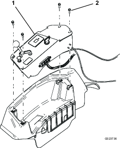
Remove the control panel (Figure 32).
-
Locate the wireless hour-meter jumper.
Note: The jumper is labeled.
-
Attach the wireless hour meter.
-
Tie the wireless hour meter to the existing harness to prevent excessive motion in the console.
-
Install the control panel.
Maintenance
Note: Determine the left and right sides of the machine from the normal operating position.
Caution
If you leave the key in the switch, someone could accidently start the engine and seriously injure you or other bystanders.
Remove the key from the switch before you do any maintenance.
Maintenance Safety
-
Before adjusting, cleaning, repairing, or leaving the machine, do the following:
-
Park the machine on a level surface.
-
Move the throttle switch to the low-idle position.
-
Lower the attachment.
-
Ensure that the traction is in neutral.
-
Engage the parking brake.
-
Shut off the engine and remove the key.
-
Wait for all moving parts to stop.
-
Allow machine components to cool before performing maintenance.
-
-
If possible, do not perform maintenance while the engine is running. Keep away from moving parts.
-
Use jack stands to support the machine or components when required.
-
Carefully release pressure from components with stored energy.
Recommended Maintenance Schedule(s)
| Maintenance Service Interval | Maintenance Procedure |
|---|---|
| After the first 8 hours |
|
| Before each use or daily |
|
| Every 100 hours |
|
| Every 200 hours |
|
| Every 300 hours |
|
| Every 400 hours |
|
| Every 800 hours |
|
Important: Refer to your engine owner's manual for additional maintenance procedures.
Pre-Maintenance Procedures
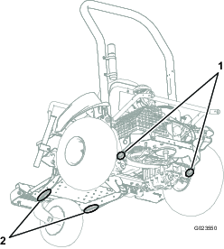
Lifting the Machine
Warning
Mechanical or hydraulic jacks may fail to support the machine and cause serious injury.
Use jack stands when supporting the machine.
Refer to Figure 33 for the support points.
Lubrication
Greasing the Machine
| Maintenance Service Interval | Maintenance Procedure |
|---|---|
| Every 100 hours |
|
Grease Type: No. 2 lithium grease
Grease each grease fitting located on the front wheel hub, the belt tensioner, and the attachment lift as follows:
-
Park the machine on a level surface, lower the attachment, move the control handles to the neutral-locked position, engage the parking brake, shut off the engine, and remove the key.
-
Wipe the grease fitting clean so that foreign matter cannot be forced into the bearing or bushing.
-
Attach a grease gun to the fitting, and pump grease into the fitting.
-
Wipe up any excess grease.
Engine Maintenance
Engine Safety
-
Shut off the engine before checking the oil or adding oil to the crankcase.
-
Do not change the governor speed or overspeed the engine.
Servicing the Engine Oil and Filter
Changing the Engine Oil
| Maintenance Service Interval | Maintenance Procedure |
|---|---|
| After the first 8 hours |
|
| Every 100 hours |
|
Toro Premium Engine Oil is available from your Authorized Toro Distributor.
Crankcase Capacity: 1.66 L (1.75 US qt) with filter change
Use 4-cycle engine oil that meets or exceeds the following requirements:
-
API service category: SJ, SL, SM, or higher
-
Viscosity: SAE 30; refer to the following chart for other viscosities (Figure 37):
Important: Using multi-viscosity oils, such as 10W-30, increases oil consumption. Check the oil level more frequently when using them.
-
Run the engine for a few minutes to warm the oil.
-
Park the machine on a level surface, lower the attachment, move the control handles to the neutral-locked position, engage the parking brake, shut off the engine, and remove the key.
-
Remove the drain plug (Figure 39) and let the oil drain into a suitable container. When the oil stops draining, install the drain plug.
Note: Insert a piece of paper or light cardboard into the drain hole to channel the oil away from the engine mounting plate (Figure 38).
-
Remove the dipstick and wipe it with a clean cloth (Figure 40).
-
Pour fresh oil into the fill tube.
-
Start the engine and let it run for about 3 minutes, and ensure that there are no leaks.
-
Stop the engine.
-
Check the oil level, and add oil if necessary.
-
Install the dipstick.
-
Dispose of the used oil according to local codes.
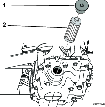
Changing the Engine Oil Filter
| Maintenance Service Interval | Maintenance Procedure |
|---|---|
| After the first 8 hours |
|
| Every 100 hours |
|
-
Run the engine for a few minutes to warm the oil.
-
Park the machine on a level surface, lower the attachment, move the control handles to the neutral-locked position, engage the parking brake, shut off the engine, and remove the key.
-
Drain the engine oil; refer to Servicing the Engine Oil and Filter.
-
Place a drain pan under the oil filter, and turn the filter counterclockwise to remove it (Figure 41).
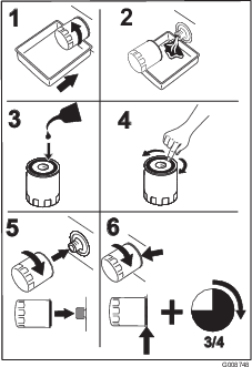
-
Apply a light coat of clean oil to the gasket of the new filter.
-
Install the new filter, turning it by hand until the gasket contacts the filter adapter; then tighten it 3/4 turn more.
Important: Do not overtighten the filter.
-
Check the oil level; refer to Checking the Level of the Engine Oil.
-
If necessary, add oil into the fill tube.
-
Start the engine and let it run for about 3 minutes, and ensure that there are no leaks.
-
Shut off the engine.
-
Check the oil level, and add oil if necessary.
Note: The filter holds some oil, so the oil level may decrease when installing a new filter.
-
Install the dipstick.
-
Dispose of the used oil according to local codes.
Servicing the Air Cleaner
Replacing the Air Filter
| Maintenance Service Interval | Maintenance Procedure |
|---|---|
| Every 200 hours |
|
Note: Changing the air filter before it is necessary only increases the chance of dirt entering the engine when the filter is removed.
-
Park the machine on a level surface, lower the attachment, move the control handles to the neutral-locked position, engage the parking brake, shut off the engine, and remove the key.
-
Release the latches securing the air-cleaner cover to the air-cleaner body (Figure 42).
-
Remove the cover from the air-cleaner body.
-
Remove the old filter, and install the new filter.
Note: Inspect the new filter for shipping damage, checking the sealing end of the filter and the body. Do not use a damaged element. Insert the new filter by applying pressure to the outer rim of the element to seat it in the canister. Do not apply pressure to the flexible center of the filter.
Note: Do not clean the used element, because it can damage the filter media.
-
Clean the dirt-ejection port located in the removable cover.
-
Install the cover so that the dirt-ejection port points downward.
-
Secure the latches.
-
Check the whole intake system for leaks, damage, or loose hose clamps.
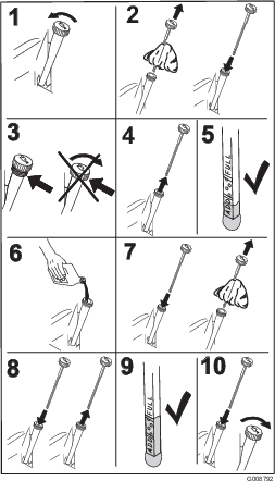
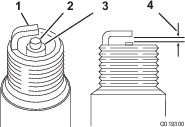
Servicing the Spark Plugs
| Maintenance Service Interval | Maintenance Procedure |
|---|---|
| Every 100 hours |
|
Type: NGK BPR4ES (or equivalent)
Gap: 0.76 mm (0.030 inch)
Note: The spark plugs usually last a long time; however, you should check them whenever the engine malfunctions.
-
Park the machine on a level surface, lower the attachment, move the control handles to the neutral-locked position, engage the parking brake, shut off the engine, and remove the key.
-
Clean the area around each of the spark plugs so that foreign matter cannot fall into the cylinders when you remove the spark plugs.
-
Disconnect the spark-plug wires from the spark plugs, and remove the plugs from the cylinder heads.
-
Check the condition of the side electrode, the center electrode, and the insulator to ensure that there is no damage.
Important: Replace the spark plugs if they are cracked, fouled, dirty, or otherwise malfunctioning. Do not clean the electrodes, because grit entering the cylinder may damage the engine.
-
For each spark plug, set the gap between the center electrode and the side electrode to 0.76 mm (0.030 inch); refer to Figure 44. Install each of the correctly gapped spark plugs with a gasket seal, and tighten the plugs to 22 N∙m (16 ft-lb).
Checking and Adjusting the Valve Clearance
| Maintenance Service Interval | Maintenance Procedure |
|---|---|
| Every 300 hours |
|
This procedure must be performed with the proper tools. See your authorized Kawasaki engine dealer for service, unless you have the proper equipment and adequate mechanical proficiency.
Cleaning and Lapping the Valve-Seating Surface
| Maintenance Service Interval | Maintenance Procedure |
|---|---|
| Every 300 hours |
|
This procedure must be performed with the proper tools. See your authorized Kawasaki engine dealer for service, unless you have the proper equipment and adequate mechanical proficiency.
Fuel System Maintenance
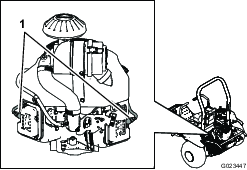
Replacing the Carbon-Canister Filter
| Maintenance Service Interval | Maintenance Procedure |
|---|---|
| Every 200 hours |
|
-
Park the machine on a level surface, lower the attachment, move the control handles to the neutral-locked position, engage the parking brake, shut off the engine, and remove the key.
-
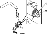
Remove the fasteners securing the seat assembly to the machine.
-
Disconnect the filter from the carbon canister (Figure 46).
-
Connect the new filter to the carbon canister.
-
Install the seat support plate and the seat.
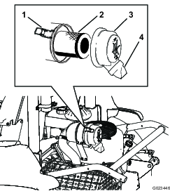
Replacing the Fuel Filter
| Maintenance Service Interval | Maintenance Procedure |
|---|---|
| Every 800 hours |
|
The fuel line has an in-line filter. Replace it as follows:
-
Park the machine on a level surface, lower the attachment, move the control handles to the neutral-locked position, engage the parking brake, shut off the engine, and remove the key.
-
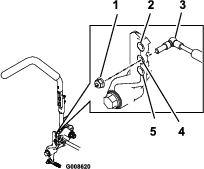
Loosen the hose clamp on the carburetor side of the filter, and remove the fuel line from the filter (Figure 47 and Figure 48).
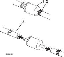
-
Place a drain pan under the filter, loosen the remaining hose clamp, and remove the filter.
-
Slide the hose clamps onto the ends of the fuel lines.
-
Push the fuel lines onto the new fuel filter, and secure them with the hose clamps.
Note: Install the new filter with the arrow on the filter body pointing away from the fuel tank (toward the carburetor).
Electrical System Maintenance
Electrical System Safety
-
Disconnect the battery before repairing the machine. Disconnect the negative terminal first and the positive last. Connect the positive terminal first and the negative last.
-
Charge the battery in an open, well-ventilated area, away from sparks and flames. Unplug the charger before connecting or disconnecting the battery.
-
Wear protective clothing and use insulated tools.
Jump-Starting the Machine
-
Remove any corrosion from the battery terminals, and ensure that the connections are tight before jump-starting the machine.
Important: Corrosion or loose connections can cause unwanted electrical voltage spikes at any time during the jump-starting procedure, which could damage the engine.Do not attempt to jump-start the machine if the battery terminals are loose or corroded.
Danger
Jump-starting a weak battery that is cracked or frozen, or has a low electrolyte level or an open/shorted battery cell, can cause an explosion resulting in serious personal injury.
Do not jump-start a weak battery if these conditions exist.
-
Ensure that the booster battery is a good, fully charged lead-acid battery with at least 12.6 V. Use properly sized jumper cables with short lengths to reduce the voltage drop between the systems. Make sure that the cables are color coded or labeled for the correct polarity.
Note: Be sure that the vent caps are tight and level. Place a damp cloth, if available, over the vent caps on each battery. Be sure that the machines do not touch and that both electrical systems are turned off and have the same rated system voltage. These instructions are for negative-ground systems only.
-
Connect the positive (+) cable to the positive (+) terminal of the discharged battery that is wired to the starter or solenoid as shown in Figure 49.
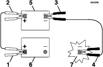
-
Connect the other end of the positive cable to the positive terminal of the booster battery.
-
Connect the black negative (–) cable to the other terminal (negative) of the booster battery.
-
Make the final connection on the engine block (not on the negative battery post) of the machine with the discharged battery, away from the battery, and stand back (Figure 50).
-
Start the engine, and remove the cables in the reverse order of connection.
Note: Disconnect the cable connected to the engine block (black cable) first.
Replacing the Fuses
Park the machine on a level surface, lower the attachment, move the control handles to the neutral-locked position, engage the parking brake, shut off the engine, and remove the key.
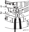
The fuse block (Figure 51) is located near the control panel.
To replace a fuse, remove it by simply pulling it out from the fuse block, and install a new fuse
Important: Always use a fuse of the same type and amperage as the one you are replacing; otherwise, you could damage the electrical system. Refer to the decal on the back of the seat for the function and amperage of each fuse.
Servicing the Battery
Charging the Battery
Warning
Charging the battery produces gases that can explode, seriously injuring you or bystanders.
Never smoke near the battery, and keep sparks and flames away from the battery.
Important: Always keep the battery fully charged. This is especially important to prevent battery damage when the temperature is below 0°C (32°F).
-
Park the machine on a level surface, lower the attachment, move the control handles to the neutral-locked position, engage the parking brake, shut off the engine, and remove the key.
-
Charge the battery for 10 to 15 minutes at 25 to 30 A, or 30 minutes at 10 A.
-
When the battery is fully charged, unplug the charger from the electrical outlet, and disconnect the charger leads from the battery posts (Figure 52).
-
Install the battery in the machine and connect the battery cables; refer to Installing the Battery.
Important: Do not run the machine with the battery disconnected; electrical damage may occur.
If the battery no longer holds a charge, replace it; refer to Removing the Battery and Installing the Battery.
Removing the Battery
-
Park the machine on a level surface, lower the attachment, move the control handles to the neutral-locked position, engage the parking brake, shut off the engine, and remove the key.
-
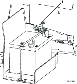
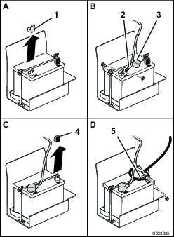
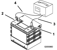
Remove the wing nuts and washers securing the battery hold-down (Figure 53).
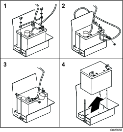
-
Disconnect the negative (black) ground cable from the battery post.
Warning
Incorrect battery cable routing could damage the machine and cables, causing sparks. Sparks can cause the battery gases to explode, resulting in personal injury.
-
Always disconnect the negative (black) battery cable before disconnecting the positive (red) cable.
-
Always connect the positive (red) battery cable before connecting the negative (black) cable.
Warning
Battery terminals or metal tools could short against metal machine components, causing sparks. Sparks can cause the battery gases to explode, resulting in personal injury.
-
When removing or installing the battery, do not allow the battery terminals to touch any metal parts of the machine.
-
Do not allow metal tools to short between the battery terminals and metal parts of the machine.
-
-
Slide the red terminal boot off the positive (+) battery terminal, and remove the positive (red) battery cable.
-
Remove the battery.
Installing the Battery
-
Place the battery in the tray.
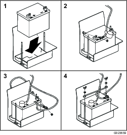
-
Install the positive (red) battery cable to the positive (+) battery terminal, and tighten the nut onto the bolt.
Important: The red cable may be covered by a wire loom. The positive cable is the one with the red boot.
-
Install the negative (black) ground cable to the negative (-) battery terminal, and tighten the nut onto the bolt.
-
Slide the red terminal boot onto the positive (+) battery post.
-
Install the hold-down, and secure it with the wing nuts and washers.
Checking and Cleaning the Battery
| Maintenance Service Interval | Maintenance Procedure |
|---|---|
| Every 100 hours |
|
Park the machine on a level surface, lower the attachment, move the control handles to the neutral-locked position, engage the parking brake, shut off the engine, and remove the key.
Keep the top of the battery clean. If the machine is stored in a location where temperatures are extremely high, the battery will discharge more rapidly than if the machine is stored in a cooler location.
Keep the top of the battery clean by washing it with a brush dipped in ammonia or a solution of sodium bicarbonate. Flush the top surface with water after cleaning. Do not remove the fill cap while cleaning the battery.
The battery cables must be tight on the terminals to provide good electrical contact.
If corrosion occurs at the battery terminals, disconnect the cables, negative (-) cable first, and scrape the clamps and terminals separately. Connect the cables, positive (+) cable first, and coat the terminals with petroleum jelly.
Drive System Maintenance
Checking the Tracking
-
Drive to a flat, open area, and move the control handles to the neutral-locked position.
-
Move the throttle midway between the FAST and SLOW positions.
-
Move both control handles all the way forward until they both hit the stops in the T-slot.
-
Check which way the machine tracks.
Adjusting the Tracking
-
Park the machine on a level surface, lower the attachment, move the control handles to the neutral-locked position, engage the parking brake, shut off the engine, and remove the key.
-
Depending on which way the machine tracks, do the following:
-
If it tracks to the right, loosen the bolts and adjust the left stop plate rearward until the machine tracks straight (Figure 55).
-
If it tracks to the left, loosen the bolts and adjust the right stop plate rearward until the machine tracks straight (Figure 55).
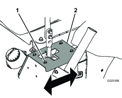
-
-
Tighten the bolts to secure the stop plate (Figure 55).
Important: Ensure that each control handle stops against the stop plate and not against the transmission internal stop.
Replacing the Drive Belt and the Tensioner Pulley
-
Park the machine on a level surface, lower the attachment, move the control handles to the neutral-locked position, engage the parking brake, shut off the engine, and remove the key.
-
Raise the rear of the machine and support it with jack stands; refer to Lifting the Machine.
Warning
Mechanical or hydraulic jacks may fail to support the machine and cause serious injury.
Use jack stands when supporting the machine.
-
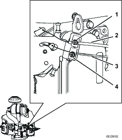
Use a ratchet in the square hole in the tensioner arm to counteract against the tensioner spring (Figure 56), and remove the belt from the tensioner pulley.
-
Unhook the tensioner spring from the tensioner arm and the frame (Figure 56).
-
Remove the nut that secures the tensioner assembly to the frame (Figure 57).
-
Remove the bolt securing the old tensioner pulley to the tensioner arm, and install a new pulley (Figure 58).
-
Remove the belt from the transmission pulleys and the engine pulley.
-
Install the new belt around the engine pulley and the 2 transmission pulleys.
-
Install the spring on the tensioner arm and the frame (Figure 56).
-
Use a ratchet in the square hole in the tensioner arm to temporarily stretch the tensioner spring, and align the belt to the tensioner pulley.
Controls System Maintenance
Adjusting the Control-Handle Position
There are 2 height positions for the control handles; high and low.
-
Park the machine on a level surface, lower the attachment, move the control handles to the neutral-locked position, engage the parking brake, shut off the engine, and remove the key.
-
Loosen the bolts and flange nuts that attach the handles to the levers (Figure 59).
-
Align the front-to-rear position of the handles by bringing them together to the neutral position, and sliding them until they are aligned (Figure 60).

-
Tighten the bolts and flange nuts to secure the handles to the levers.
Adjusting the Control-Handle Linkage
Turning the double nuts on the control-handle linkage allows you to fine-tune the adjustment so that the machine does not move in neutral. Make adjustments for neutral positioning only.
Warning
To adjust the control-handle linkage, the engine must be running and the drive wheels must be able to turn. Contact with moving parts or hot surfaces may cause personal injury.
Keep hands, feet, other body parts, and clothing away from rotating parts and hot surfaces.
-
Park the machine on a level surface, lower the attachment, move the control handles to the neutral-locked position, engage the parking brake, shut off the engine, and remove the key.
-
Raise all 3 wheels of the machine up off the floor, and support the machine with jack stands just high enough to allow the drive wheels to turn freely; refer to Lifting the Machine.
Warning
Mechanical or hydraulic jacks may fail to support the machine and cause serious injury.
Use jack stands when supporting the machine.
-
Press down on the seat, or place a weight on the seat, to press the interlock switch down.
-
Start the engine and move the throttle lever to the Fast position.
-
Remove the pressure (or weight) from the seat.
-
Disengage the parking brake.
-
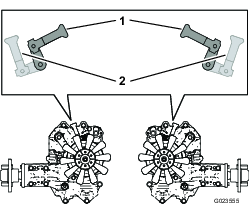
On 1 side of the machine, slowly turn the double nuts on the linkage (Figure 61) until the wheel on that side starts to rotate, then turn the double nuts in the opposite direction until the wheel rotates in the other direction.
Note: The control handles need to be in the neutral position while making any necessary adjustments.
-
Turn the double nuts back the other way until they are at the midpoint between the 2 positions.
-
Repeat steps 7 and 8 for the other side.
-
Shut off the engine.
-
Remove the jack stands, and carefully lower the machine to the ground.
-
Start the engine again, and ensure that the machine does not creep in neutral with the parking brake disengaged.
Adjusting the Control-Handle Dampers
You can adjust the top damper-mounting bolt to change the control-handle resistance.
-
Park the machine on a level surface, lower the attachment, move the control handles to the neutral-locked position, engage the parking brake, shut off the engine, and remove the key.
-
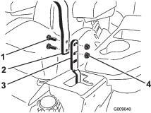
To access the damper-mounting bolts, remove the bolts that secure the stop plates to the frame (Figure 62).
-
Remove the locknut, move the damper-mounting bolt to the desired position, and install the locknut. Refer to Figure 63 for the mounting options.
Note: Torque the locknut to 22.6 N∙m (16.7 ft-lb). The bolt must protrude past the end of the locknut when it is tight.
-
Adjust the tracking; refer to Adjusting the Tracking.
Adjusting the Neutral-Lock Resistance
If you prefer a different amount of side-to-side resistance in the control handles when you move them into and out of the neutral-locked position, you can adjust it as follows:
-
Park the machine on a level surface, lower the attachment, move the control handles to the neutral-locked position, engage the parking brake, shut off the engine, and remove the key.
-
Loosen the jam nut (Figure 64).
-
Tighten or loosen the flanged nut to the desired feel.
-
For more resistance, tighten the flanged nut.
-
For less resistance, loosen the flanged nut.
-
-
Tighten the jam nut.
-
Repeat this procedure for the other control handle.
Adjusting the Engine Controls
Adjusting the Throttle Control
Proper throttle operation depends upon proper adjustment of the throttle control. Before adjusting the carburetor, ensure that the throttle control is operating properly.
-
Park the machine on a level surface, lower the attachment, move the control handles to the neutral-locked position, engage the parking brake, shut off the engine, and remove the key.
-
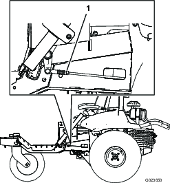
Loosen the clamp screw securing the throttle-cable housing to the engine (Figure 65).
-
Move the throttle control forward to the Fast position.
-
Pull up the cable housing of the throttle cable (Figure 65) until the throttle cable has almost no slack, and tighten the clamp screw.
-
Tighten the clamp screw and check the engine speed:
-
High idle: 2750 to 2950 rpm
-
Low idle: 1450 to 1650 rpm
-
Adjusting the Choke Control
-
Park the machine on a level surface, lower the attachment, move the control handles to the neutral-locked position, engage the parking brake, shut off the engine, and remove the key.
-
Loosen the clamp screw securing the choke-cable housing to the engine (Figure 65).
-
Push the choke control down to the OPEN position; refer to Choke Control.
-
Ensure that the choke valve on the carburetor is fully opened.
-
Pull up the cable housing of the choke cable (Figure 65) until the choke cable has almost no slack, and tighten the clamp screw.
-
Ensure that the choke valve moves to the fully closed position when you pull the choke control outward and to the fully opened position when you push the choke control downward.
Adjusting the Engine Governor Speed Control
Warning
The engine must be running during adjustment of the engine governor speed control. Contact with moving parts or hot surfaces may cause personal injury.
-
Ensure that the control handles are in the neutral-locked position, and engage the parking brake before performing this procedure.
-
Keep hands, feet, clothing, and other body parts away from any rotating parts, the muffler, and other hot surfaces.
Adjust the low-idle speed as follows:
-
Start the engine and let it run at half throttle for approximately 5 minutes to warm up.
-
Move the throttle control to the SLOW setting.
-
Push the spring end of the governor arm downward (Figure 66).
-
Adjust the stop screw on the carburetor (Figure 67) so that the idle speed is 1350 to 1550 rpm.
Note: Check the speed with a tachometer.
-
Allow the governor arm to return to the original position.
-
Loosen the jam nut on the low-idle speed setscrew.
-
Adjust the low-idle speed setscrew so that the idle speed is 1450 to 1650 rpm.
-
Tighten the jam nut.
Adjust the high-idle speed as follows:
Important: Do not adjust the high-idle speed with the air cleaner removed.
-
Start the engine and allow it to warm up thoroughly.
-
Loosen the jam nut on the high-idle speed setscrew a few turns.
-
Move the throttle control so that the idle speed is 2750 to 2950 rpm.
-
Tighten the high-idle speed setscrew so that it just touches the tab on the speed-control lever.
-
Tighten the jam nut.
Hydraulic System Maintenance
Hydraulic System Safety
-
Seek immediate medical attention if fluid is injected into skin. Injected fluid must be surgically removed within a few hours by a doctor.
-
Ensure that all hydraulic-fluid hoses and lines are in good condition and all hydraulic connections and fittings are tight before applying pressure to the hydraulic system.
-
Keep your body and hands away from pinhole leaks or nozzles that eject high-pressure hydraulic fluid.
-
Use cardboard or paper to find hydraulic leaks.
-
Safely relieve all pressure in the hydraulic system before performing any work on the hydraulic system.
Checking the Hydraulic System
Whenever you repair or replace a hydraulic component, you should replace the hydraulic-fluid filters and check the hydraulic system to ensure that it works properly.
Important: Make sure that the hydraulic reservoirs and the manifold filter are filled with fluid at all times when checking the hydraulic system.
-
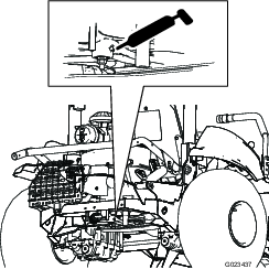
Park the machine on a level surface, lower the attachment, move the control handles to the neutral-locked position, engage the parking brake, shut off the engine, and remove the key.
-
Raise all 3 wheels of the machine up off the floor, and support the machine with jack stands just high enough to allow the drive wheels to turn freely; refer to Lifting the Machine.
Warning
Mechanical or hydraulic jacks may fail to support the machine and cause serious injury.
Use jack stands when supporting the machine.
-
Start the engine and set the throttle to allow the engine to run at low idle.
-
Move the control handles to the full-forward position, and watch for the drive wheels to turn smoothly.
-
Move the control handles to the full-reverse position, and watch for the drive wheels to turn smoothly.
-
Press the attachment switch until the lift-cylinder rod moves in and out several times.
If the cylinder rod does not move after 10 to 15 seconds, or if the pump makes abnormal sounds, shut off the engine immediately and determine the cause or problem.
Inspect for the following conditions, and make the necessary repairs or see your authorized Toro distributor:
-
The belt is removed or severely worn.
-
The fluid level is inadequate.
-
A hydraulic filter is loose.
-
The charge pump is worn.
-
The charge relief filter is worn.
-
There is an issue with the switch or the wiring.
-
The solenoid valve is plugged.
-
Changing the Hydraulic Fluid and Filters
| Maintenance Service Interval | Maintenance Procedure |
|---|---|
| After the first 8 hours |
|
| Every 400 hours |
|
Capacity:
-
Left side—1.9 L (2.0 US qt)
-
Right side—2.0 L (2.1 US qt)
Fluid Type: Toro Premium Transmission/Hydraulic Tractor Fluid or Mobilfluid® 424
-
Park the machine on a level surface, lower the attachment, move the control handles to the neutral-locked position, engage the parking brake, shut off the engine, and remove the key.
-
Place a drain pan under the left hydrostatic transmission.
-
Remove the drain plug on the pump side and the drain plug on the gear side (Figure 69), and allow the oil to drain completely.
-
Remove the filter cap, and pull the filter out of the transmission (Figure 70).
-
Install a new filter, and install the filter cap.
-
Repeat steps 2 through 5 for the right hydrostatic transmission.
-
Clean the area around the manifold filter, which is located on the right side of the machine.
-
Place a drain pan under the manifold filter (Figure 71).
-
Slowly loosen the manifold filter until fluid flows past the gasket and drips out.
-
Remove the filter when the fluid flow slows.
-
Lubricate the sealing gasket on the replacement filter with clean hydraulic fluid, and install it by hand until the gasket contacts the mounting surface.
-
Tighten the filter 3/4 turn further.
-
Fill each of the hydraulic reservoirs with fresh hydraulic fluid until the level is at the bottom of the sight windows in the reservoir brackets.
Important: Do not overfill the hydraulic system. Refer to Checking the Level of the Hydraulic Fluid.
Note: To allow the fluid to flow into the system more quickly, you can remove the plug (Figure 72) on top of each hydrostatic transmission. When fluid starts to come out of the hole, install the plug and continue filling the reservoir until the fluid is at the correct level.
Important: Ensure that the plugs are in place and secure before starting the engine.
-
Start and run the engine. Operate the lift cylinder until it extends and retracts.
-
Check to ensure that the machine can drive forward and backward.
-
Shut off the engine and check the fluid level in reservoir, add fluid if necessary.
-
Check the connections for leaks, and ensure that the hydraulic system works properly; refer to Checking the Hydraulic System.
-
Dispose of the used fluid properly.
Checking the Hydraulic Lines and Hoses
| Maintenance Service Interval | Maintenance Procedure |
|---|---|
| Before each use or daily |
|
Check the hydraulic lines and hoses daily for leaks, kinked lines, loose mounting supports, wear, loose fittings, weather deterioration, and chemical deterioration. Make all necessary repairs before operating.
Cleaning
Inspecting and Cleaning the Machine
| Maintenance Service Interval | Maintenance Procedure |
|---|---|
| Before each use or daily |
|
-
At the completion of operation, park the machine on a level surface, lower the attachment, move the control handles to the neutral-locked position, engage the parking brake, shut off the engine, and remove the key.
-
Thoroughly wash the machine with a garden hose—without a nozzle—so that excessive water pressure does not cause contamination and damage to the seals and bearings.
-
Make sure that the cooling fins and the area around the engine-cooling air intake are free of debris. After cleaning, inspect the machine for possible hydraulic-fluid leaks, damage, or wear to hydraulic and mechanical components.
Storage
Storing the Machine
-
Park the machine on a level surface, move the control handles to the neutral-locked position, engage the parking brake, shut off the engine, and remove the key.
-
Thoroughly clean the machine, the attachments, and the engine.
-
Check the tire pressure. Inflate the tires to 48 kPa (7 psi).
-
Check all fasteners for looseness; tighten as necessary.
-
Grease or oil all grease fittings and pivot points. Wipe off any excess lubricant.
-
Lightly sand and use touch-up paint on painted areas that are scratched, chipped, or rusted.
-
Change the engine oil and filter; refer to Servicing the Engine Oil and Filter.
-
Condition the fuel system as follows:
-
Add a petroleum-based stabilizer/conditioner to fuel in the tank. Follow the mixing instructions from the stabilizer manufacturer. Do not use an alcohol-based stabilizer (ethanol or methanol).
Toro fuel stabilizer is available from your Authorized Toro Distributor.
Important: Do not store fuel containing stabilizer/conditioner longer than the duration recommended by the fuel-stabilizer manufacturer.
Note: Fuel stabilizer/conditioner is most effective when mixed with fresh fuel and used at all times.
-
Run the engine for 5 minutes to distribute the conditioned fuel through the fuel system.
-
Shut off the engine, allow it to cool, and drain the fuel tank using a pump-type siphon. Dispose of fuel properly; recycle it according to local codes.
-
Start the engine and run it until it shuts off.
-
Choke the engine.
-
Start and run the engine until it does not start again.
-
-
Thoroughly clean and service the air-cleaner assembly. Refer to Servicing the Air Cleaner.
-
Seal the air cleaner inlet and the exhaust outlet with weatherproof masking tape.
-
Check the dipstick and fuel-tank cap to ensure that they are securely in place.
-
Service the battery and cables as follows:
-
Remove the battery terminals from the battery posts.
-
Clean the battery, terminals and posts with a wire brush and baking soda solution.
-
Coat the cable terminals and battery posts with Grafo 112X skin-over grease (Toro Part No. 505-47), or petroleum jelly to prevent corrosion.
-
Slowly charge the battery for 24 hours every 60 days to prevent lead sulfation of the battery.
Note: The specific gravity of a fully charged battery is 1.250.
Note: Store the battery in a cool environment to avoid quick deterioration of the charge in the battery. To prevent the battery from freezing, make sure that it is fully charged.
-
Troubleshooting
| Problem | Possible Cause | Corrective Action |
|---|---|---|
| The starter does not crank. |
|
|
| The engine does not start, starts hard, or fails to keep running |
|
|
| The engine loses power. |
|
|
| The engine overheats. |
|
|
| The machine pulls to the left or the right (with the control handles fully forward). |
|
|
| The machine does not drive. |
|
|
| The machine vibrates abnormally. |
|
|