Setup
Preparing the Machine
-
Park the machine on a level surface.
-
Engage the parking brake.
-
Shut off the engine and remove the key.
-
Disconnect the battery; refer to your Operator’s Manual.
-
Raise the cargo bed to the dump position and secure it with the prop rod.
Drilling the Holes for the Mounting Tubes
Installing the Front Mounting Tubes
Parts needed for this procedure:
| Front mounting tube | 2 |
| Flange-head bolt (5/16 x 3 inches) | 2 |
| Spacer (5/8 x 1 inch) | 2 |
| Flange nut (5/16 inch) | 4 |
| Carriage bolt (5/16 x 2 inches) | 2 |
Loosely install the 2 front mounting tubes using 2 flange-head bolts (5/16 x 3 inches), 2 spacers (5/8 x 1 inch), 4 flange nuts (5/16 inch), and 2 carriage bolts (5/16 x 2 inches) as shown in Figure 3.
Removing the Side Panels
For Gasoline Machines
Important: Before performing this procedure, check your machine to see if the holes for installation already exist. If not, proceed with this procedure.
Note: Retain all the hardware that you remove in this procedure.
-
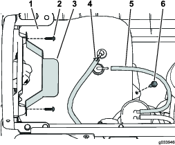
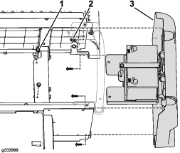
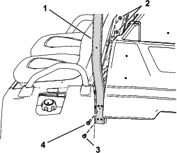
Remove the flange-head bolt securing the fuel tank to the tank tray (Figure 4).
-
Remove the screws securing the hold-down (Figure 4).
-
Disconnect the vent tube and fuel line from the tank (Figure 4).
Note: Prepare to capture and clean up any fuel that spills when you disconnect the fuel line from the tank.
Danger
In certain conditions, fuel is extremely flammable and highly explosive. A fire or explosion from fuel can burn you and others and can damage property.
-
Drain the fuel from the fuel tank when the engine is cold. Do this outdoors and in an open area. Wipe up any fuel that spills.
-
Never smoke when handling fuel, and stay away from an open flame or where a spark may ignite fuel fumes.
-
-
Remove the fuel tank from the tray.
-
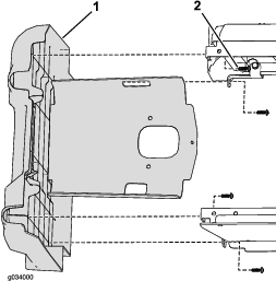
Remove the 2 flange-head bolts securing the tank tray to the frame (Figure 5).
-
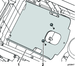
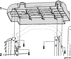
Remove the 4 screws securing the left side panel to the lower seat assembly (Figure 6).
-
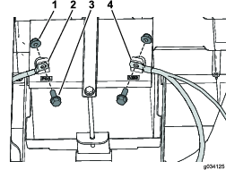
Remove the negative (–) cable from the battery and then the positive (+) cable (Figure 7).
-
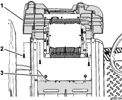
Remove the 2 flange-head bolts securing the battery tray to the frame (Figure 8).
-
Remove the 4 screws securing the right side panel to the lower seat assembly (Figure 8).
For Electric Machines
Important: Before performing this procedure, check your machine to see if the holes for installation already exist. If not, proceed with this procedure.
Note: Retain all the hardware that you remove in this procedure.
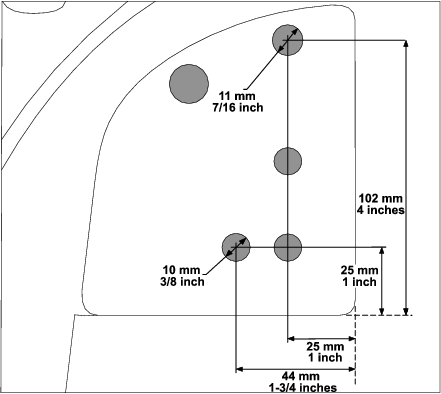
Drilling the Support Bracket
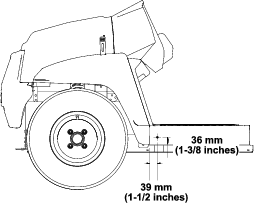
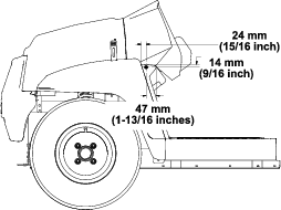
Drill the support bracket using the measurements shown in Figure 11.
When you drill the highest upper hole, ensure that you drill all the way through the outer bracket, frame tube, and firewall.
Caution
Use caution when drilling the holes into the right side of the frame on an electric machine.
If you drill too far, you could damage the batteries or other components.
Installing the Side Panels
For Gasoline Machines
-
Secure the right side panel using the previously removed 4 screws (Figure 8).
-
Secure the battery tray to the frame using the previously removed 2 flange-head bolts (Figure 8).
-
Secure the battery cables using the previously removed 2 bolts and 2 nuts and connect the battery terminals (Figure 7).
-
Secure the left side panel using the previously removed 4 screws (Figure 6).
-
Secure the tank tray to the frame using the previously removed 2 flange-head bolts (Figure 5).
-
Place the fuel tank in the tank tray.
-
Connect the fuel line and vent tube to the fuel tank (Figure 4).
-
Secure the hold-down using the previously removed screws (Figure 4).
-
Secure the fuel tank to the tank tray using the previously removed flange-head bolt (Figure 4).
-
Fill the fuel tank; refer to the Operator’s Manual.
For Electric Machines
Installing the Rear Mounting Tubes and Tube-Mounting Bracket
Parts needed for this procedure:
| Rear mounting tube | 2 |
| Tube-mounting bracket | 1 |
| Flange-head bolt (5/16 x 3 inches) | 2 |
| Flange nut (5/16 inch) | 2 |
| Flange-head bolt (3/8 x 1-3/4 inches) | 2 |
| Flange-head bolt (3/8 x 3-1/2 inches) | 2 |
| Locknut (3/8 inch) | 4 |
| Trim seal | 1 |
-
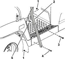
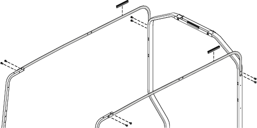
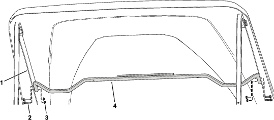
Loosely install the 2 rear mounting tubes using 2 flange-head bolts (3/8 x 3-1/2 inches), 2 flange-head bolts (3/8 x 1-3/4 inches), and 4 locknuts (3/8 inch) as shown in Figure 12.
-
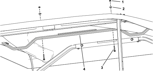
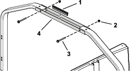
Secure the tube-mounting bracket to the rear mounting tubes using 2 flange-head bolts (5/16 x 3 inches) and 2 flange nuts (5/16 inch) as shown in Figure 13.
-
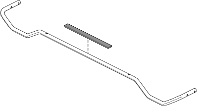
Install the trim seal onto the tube-mounting bracket (Figure 13).
-
Tighten the fasteners installed in step 1.
Torque the 5/16-inch fasteners to 20 to 25 N∙m (175 to 225 in-lb).
Torque the 3/8-inch fasteners to 37 to 45 N∙m (27 to 33 ft-lb).
Installing the Long Canopy Support Brackets
Parts needed for this procedure:
| Long canopy support bracket | 2 |
| Hex-washer head bolt (5/16 x 3/4 inch) | 8 |
| Trim seal | 2 |
Installing the Canopy
Parts needed for this procedure:
| Canopy | 1 |
| Flange-head bolt (1/4 x 1-3/4 inches) | 4 |
| Sealing washer | 4 |
| Locknut (1/4 inch) | 4 |
Important: If you are installing a mirror kit, install it before installing the canopy.
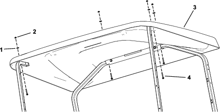
Secure the canopy to the front and rear mounting tubes using 4 flange-head bolts (1/4 x 1-3/4 inches), 4 sealing washers, and 4 locknuts (1/4 inch) as shown in Figure 15.
Installing the Canopy Support Bracket
Parts needed for this procedure:
| Canopy support bracket | 1 |
| Flange-head bolt (1/4 x 2-1/4 inches) | 2 |
| Locknut (1/4 inch) | 2 |
| Sealing washer | 2 |
| Trim seal | 1 |
| Spacer (1/4 inch) | 2 |
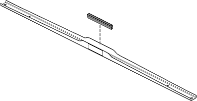
Installing the Canopy Support Tube
Parts needed for this procedure:
| Canopy support tube | 1 |
| Locknut (1/4 inch) | 6 |
| Sealing washer | 2 |
| Flange-head bolt (1/4 x 1-1/2 inches) | 2 |
| Foam pad | 1 |
| Flange-head bolt (1/4 x 1-1/4 inches) | 4 |
-
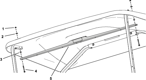
Apply the foam pad to the canopy support tube (Figure 18).
-
Secure the canopy support tube to the long canopy support brackets using 4 flange-head bolts (1/4 x 1-1/4 inches) and 4 locknuts (1/4 inch) as shown in Figure 19.
-
Using the canopy support tube as the template, drill 2 holes (6 mm or 1/4 inch) into the canopy.
-
Secure the canopy support tube to the canopy using 2 flange-head bolts (1/4 x 1-1/2 inches), 2 sealing washers, and 2 locknuts (1/4 inch) as shown in Figure 20.