Setup
Preparing for the Install
Important: The machine must have the 2/3 or full truck bed installed on the machine.
Important: Machines with serial numbers 239999999 and below must have the remote hydraulic control kit installed.Machines with serial numbers 240000000 and above must have the high flow hydraulic kit installed.
-
Park the machine on a level surface.
-
Engage the parking brake.
-
Shut off the engine and remove the key from the key switch.
-
Read and become familiar with the Operator’s Manual that you received with the core harvester.
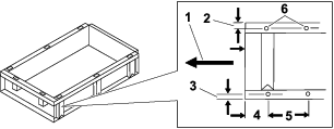
Drilling the Mounting Holes
Drilling the Mounting Holes on a Full Bed
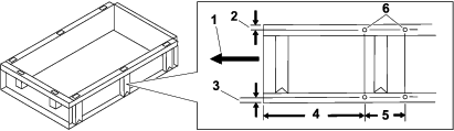
Drilling the Mounting Holes on a 2/3 Bed
Mounting the Harvester
Parts needed for this procedure:
| Mounting plate (HD/HDX) | 1 |
| Mounting plate (3000/4000) | 1 |
| Mounting bracket | 1 |
| Bolt (5/16 x 2-3/4 inches) | 2 |
| Washer (3/8 inch) | 4 |
| Lock washer (5/16 inch) | 2 |
| Nut (5/16 inch) | 2 |
| Bolt (3/8 x 1-3/4 inches) | 2 |
| Washer (7/16 inch) | 2 |
| Lock washer (3/8 inch) | 2 |
| Nut (3/8 inch) | 2 |
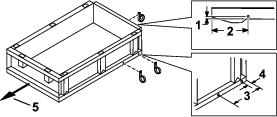
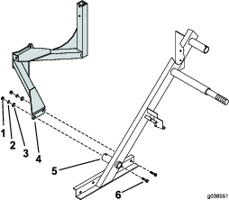
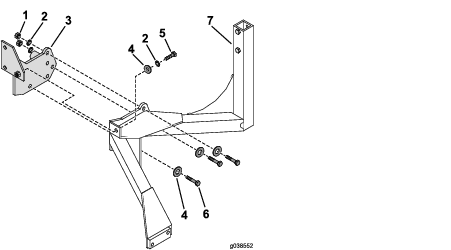
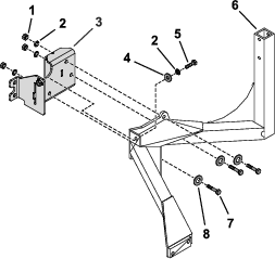
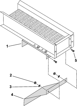
Installing the Mounting Bracket
-
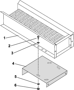
Use the 2 bolts (5/16 x 2-3/4 inches), washers, lock washers, and nuts to secure the upper portion of the mounting bracket to the harvester frame (Figure 4).

-
Use the 2 bolts (3/8 x 1-3/4 inches), washers, lock washers, and nuts to secure the lower portion of the mounting bracket to the harvester frame (Figure 5).
Mounting the Core Harvester to the Machine
Parts needed for this procedure:
| Bolt (1/2 x 1-1/4 inches) | 3 |
| Bolt (1/2 x 1 inch) | 1 |
| Flat washer (1/2 inch) | 4 |
| Lock washer (1/2 inch) | 4 |
| Nut (1/2 inch) | 3 |
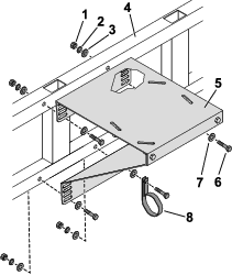
Mounting the Frame to the Mounting Plate
Mounting the Frame to the Mounting Plate
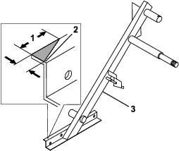
Modifying the Core-Harvester Frame
Important: Perform this procedure if necessary.
-
Ensure that there is clearance between the core-harvester frame and the front tire when you turn them from side to side.
-
If required, use a cutting tool to remove the corner on the core-harvester frame to eliminate the interference with the front tire (Figure 8).
Installing the Handle Extension
Parts needed for this procedure:
| Handle extension | 1 |
| Bolt (1/4 x 1-1/2 inches) | 1 |
| Lock washer (1/4 inch) | 1 |
| Nut (1/4 inch) | 1 |
-
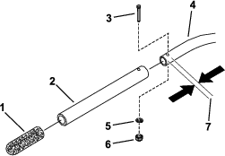
Remove and set aside the grip from the handle on the core harvester (Figure 9).
-
Drill a 9/16 hole, 2.5 cm (1 inch) from the end hole of the core-harvester handle (Figure 9).
-
Use the bolt (1/4 x 1-1/2 inches), lock washer, and nut to secure the handle extension to the core-harvester handle (Figure 9).
-
Slide the grip onto the handle extension (Figure 9)
Installing the Hose Retainer
Parts needed for this procedure:
| Hose retainer | 3 |
| Bolt (3/8 x 1 inch) | 3 |
| Lock washer (3/8 inch) | 3 |
| Nut (3/8 inch) | 3 |
| Hose retainer (2-1/2 inches) | 3 |
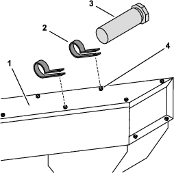
Use the 3 bolts (3/8 x 1 inch), washers, and lock washer to secure the hose retainer to the bed (Figure 10).
Installing the Manual Tube
Parts needed for this procedure:
| Manual tube | 1 |
| R-clamp | 2 |
-
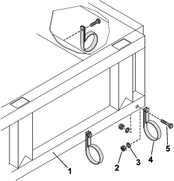
Remove and set aside the existing hardware on the core-harvester elevator shown in Figure 11.
-
Use the existing hardware to loosely install the 2 R-clamps to the core-harvester elevator (Figure 11).
-
Insert the manual tube into the R-clamps.
-
Tighten the loose hardware to secure the manual tube to the core-harvester elevator.
Mounting Brackets to the Conveyor
Parts needed for this procedure:
| Upper bracket | 1 |
| Lower bracket | 1 |
| Hose mount | 1 |
| Bolt (3/8 x 1 inch) | 8 |
| Lock washer (3/8 inch) | 8 |
| Flat washer (3/8 inch) | 8 |
| Nut (3/8 inch) | 8 |
| Hose retainer (2-1/2 inches) | 1 |
-
Use the existing hardware to secure the conveyor to the upper bracket (Figure 12).
-
Use the 2 bolts (3/8 x 1 inch), washers, and nuts to secure the lower bracket to the upper bracket (Figure 13).
-
Use the 6 bolts (3/8 x 1 inch), washers, and nuts to secure the conveyor to the side of the bed (Figure 14).
Checking the Inflation
-
Inflate the air shock on the machine to level the bed.
Important: Do not exceed 1034 kPa (150 psi) air pressure when you inflate the air shock.
-
Ensure that the castor tire on the core harvester is inflated to 69 to 82 kPa (10 to 12 psi)
Installing the Hydraulic Components—For Models Serial No. 240000001 and Above
Parts needed for this procedure:
| 90° fitting (5/8 x 1/2 inch) | 1 |
| Straight fitting | 2 |
| Hydraulic hose A—254 cm (100 inches, 8 FJ to 6 MP) | 1 |
| Hydraulic hose B—330 cm (130 inches, 8 MP to 6 MP) | 1 |
| Hose cover—122 cm (48 inches) | 1 |
| Hose cover—147 cm (58 inches) | 1 |
| Hose cover—224 cm (88 inches) | 1 |
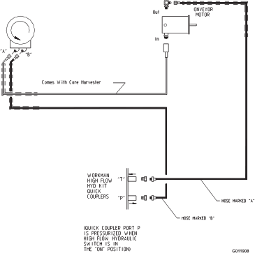
Connecting the Hydraulic Hoses
Note: The machine must have the high flow hydraulic control kit (Model No. 07228 or Model No. 07316) installed.
-
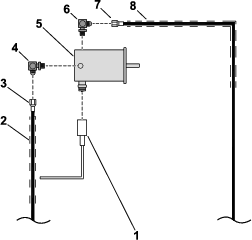
Install the hose cover 147 cm (58 inches) to the hydraulic hose A—254 cm (100 inches, 8 FJ to 6 MP) as shown in Figure 15.
-
Install one end of the 90° fitting (5/8 x 1/2 inch) to the hydraulic motor and the other end to the hydraulic hose A—254 cm (100 inches, 8 FJ to 6 MP) as shown in Figure 15.
-
Connect the hydraulic hose included with the core harvester to the IN port on the conveyor motor (Figure 15).
Connecting the Elevator Motor
-
Install the hose cover 122 cm (48 inches) over the hydraulic hose included with the core harvester (Figure 16).
-
Install the hose cover 224 cm (88 inches) over the hydraulic hose B—330 cm (130 inches, 8 MP to 6 MP) as shown in (Figure 16).
-
Connect the hydraulic hose included with the core harvester to port A on the elevator motor (Figure 16).
-
Connect the hydraulic hose B—330 cm (130 inches, 8 MP to 6 MP) from the port T quick coupler on the workman to port B on the elevator motor (Figure 16).
-
Slide the hose covers toward the elevator motor.
Connecting the Hydraulic Hoses to the Machine
Warning
Hydraulic fluid escaping under pressure can penetrate skin. Fluid injected into the skin must be surgically removed within a few hours by a doctor familiar with this form of injury, or gangrene may result.
-
Keep your body and hands away from pinhole leaks or nozzles that eject high-pressure hydraulic fluid.
-
Use cardboard or paper to find hydraulic leaks; never use your hands.
Important: Workman quick coupler (port P) is under pressure when the high flow-hydraulic switch is in the ON position.
-
Securely install the straight coupler (3/8 NPT) to the hydraulic hose 254 cm (100 inches, 8 FJ to 6 MP) as shown in Figure 17.
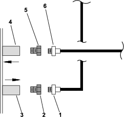
-
Securely install the straight coupler (3/8 NPT) to the hydraulic hose B—330 cm (130 inches, 8 MP to 6 MP) as shown in Figure 17.
-
Connect the hydraulic hose to the machine.
Important: Always cover the connectors when you disconnect them to prevent damaging the hydraulic system.
Installing the Hydraulic Components—For Models with Serial No. 239999999 and Below
Parts needed for this procedure:
| Hydraulic motor—Acquired separately (Part No. 92-4240) | 1 |
| Seal—Acquired separately (Part No. 92-4329) | 1 |
| Elbow—Acquired separately (Part No. 01-201-4210) | 2 |
| Barb fitting—Acquired separately (Part No. 01-201-4500) | 1 |
| Tee fitting—Acquired separately (Part No. 01-201-4510) | 1 |
| Fitting cap—Acquired separately (Part No. 01-201-4520) | 1 |
| Hydraulic hose—Acquired separately (Part No. 01-312-5610) | 1 |
| Hydraulic coupler | 1 |
| 90° fitting (5/8 x 1/2 inch) | 1 |
| Hydraulic hose A—254 cm (100 inches, 8 FJ to 6 MP) | 1 |
| Hydraulic hose B—330 cm (130 inches, 8 MP to 6 MP) | 1 |
| Hose cover—122 cm (48 inches) | 1 |
| Hose cover—147 cm (58 inches) | 2 |
| Hose cover—224 cm (88 inches) | 1 |
Connecting the Hydraulic Hoses
Note: The machine must have the remote hydraulic control kit installed.
Warning
Hydraulic fluid escaping under pressure can penetrate skin. Fluid injected into the skin must be surgically removed within a few hours by a doctor familiar with this form of injury, or gangrene may result.
-
Keep your body and hands away from pinhole leaks or nozzles that eject high-pressure hydraulic fluid.
-
Use cardboard or paper to find hydraulic leaks; never use your hands.
-
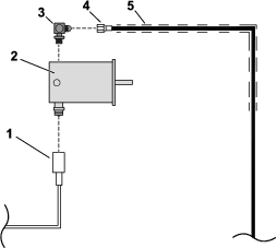
Remove the hydraulic motor (Part No. 832401) that is install on the core harvester.
-
Install the hydraulic motor (Part No. 92-4240).
-
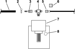
Install the hose cover 147 cm (58 inches) to the hydraulic hose (Part No. 01-312-5610) as shown in Figure 18.
-
Install the hose cover 147 cm (58 inches) to the hydraulic hose A—254 cm (100 inches, 8 FJ to 6 MP) as shown in Figure 18.
-
Install one end of the 90° fitting (5/8 x 1/2 inch) to the hydraulic motor (Part No. 92-4240) and the other end to the hydraulic hose (Part No. 01-312-5610) as shown in Figure 18.
-
Install one end of the Elbow fitting (Part No. 01-201-4210) to the hydraulic motor (Part No. 92-4240) and the other end to the hydraulic hose 254 cm (100 inches, 8 FJ to 6 MP) as shown in Figure 18.
-
Connect the hydraulic hose included with the core harvester to the IN port on the conveyor motor (Figure 18).
-
Slide the hose covers toward the hydraulic motor.
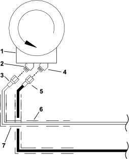
Connecting to the PTO
-
Install the tee fitting to the power takeoff (PTO) on the machine (Figure 19).
Note: Connect the tee fitting (Part No. 01-201-4510) to the hydraulic port if the machine does not have a PTO drive.
-
Slide the hose clamp over the filter-return hose (Figure 19).
-
Insert the barb fitting (Part No. 01-201-4500) into the filter-return hose (Figure 19).
-
Use the hose clamp to secure the barb fitting (Part No. 01-201-4500) to the filter-return hose (Figure 19).
-
Connect the hydraulic hose (Part No. 01-312-5610) to the tee fitting (Part No. 01-201-4510) as shown in Figure 19.
Important: Ensure that all the connectors are free of debris before you make the connection.
Important: Always cover the connectors when you disconnect them to prevent damage to the hydraulic system.
Connecting the Elevator Motor
-
Install the hose cover 122 cm (48 inches) over the hydraulic hose included with the core harvester (Figure 20).
-
Install the hose cover 224 cm (88 inches) over the hydraulic hose B—330 cm (130 inches, 8 MP to 6 MP) as shown in Figure 20.
-
Connect the hydraulic hose included with the core harvester to port A on the elevator motor (Figure 20).
Important: Ensure that all the connectors are free from debris before you make the connection.
-
Connect the hydraulic hose B—330 cm (130 inches, 8 MP to 6 MP) from the port B quick coupler on the workman to port B on the elevator motor (Figure 20).
-
Slide the hose covers toward the elevator motor.
Connecting the Hydraulic Hoses to the Machine
Warning
Hydraulic fluid escaping under pressure can penetrate skin. Fluid injected into the skin must be surgically removed within a few hours by a doctor familiar with this form of injury, or gangrene may result.
-
Keep your body and hands away from pinhole leaks or nozzles that eject high-pressure hydraulic fluid.
-
Use cardboard or paper to find hydraulic leaks; never use your hands.
Important: Workman quick coupler (port B) is under pressure when the remote hydraulic is in the ON position.
-
Ensure that the remote-hydraulic lever is set to the OFF position.
-
Install the quick coupler included with the core harvester to the hydraulic hose A—254 cm (100 inches, 8 FJ to 6 MP) that you connected to the motor (92-4240) as shown in Figure 21.
-
Install the quick coupler included with the kit to the hydraulic hose B—330 cm (130 inches, 8 MP to 6 MP)
-
Connect the hydraulic hose to the machine.
Important: Always cover the connectors when you disconnect them to prevent damage to the hydraulic system.
Checking the Hydraulic Fluid
Important: The hydraulic system on the machine operates on Dexron III automatic transmission fluid. The hydraulic fluid in the core harvester must be the same or compatible fluid. Damage occurs when you use non-compatible fluid.
-
Ensure that the hydraulic fluid in the core harvester is compatible with the hydraulic fluid in the machine.
-
Ensure that the packing brake is engaged and start the machine.
-
Operate the hydraulic system.
-
Check the level of the hydraulic fluid and add if required; refer to the Operator's Manual for the machine.
Checking for Interference
-
Ensure that the packing brake is engaged and start the machine.
-
Ensure that the conveyor is aimed toward the center of the bed.
-
Raise and lower the bed to ensure that the it does not interfere with the elevator.
-
Ensure that the hydraulic hoses are not pinch or pulled when you raise and lower the bed.
Schematics
Hydraulic Schematic for Workman Models Prior to Serial Number 239999999
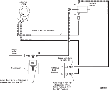
Hydraulic Schematic for Workman Models Serial Range 240000001 and Up