Warning
CALIFORNIA
Proposition 65 Warning
Use of this product may cause exposure to chemicals known to the State of California to cause cancer, birth defects, or other reproductive harm.
Safety
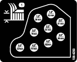
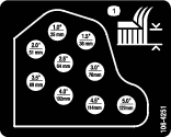
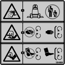
Safety and Instructional Decals
 |
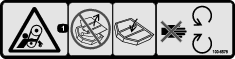
Safety decals and instructions are easily visible to the operator and are located near any area of potential danger. Replace any decal that is damaged or missing. |


Installation
Note: If the service cutting unit is used on Model 30411 or 30413, install the Deck Sensor Kit, Part No. 119-5307 on the cutting unit.
-
Park the machine on a level surface, disengage the PTO, lower the cutting unit, engage the parking brake, and set the traction pedal in the NEUTRAL position, the PTO switch is OFF.
-
Shut off the engine and remove the key from the switch.
-
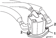
Remove the bolts securing the hydraulic motors to the cutting unit (Figure 1).
-
Lift the motors off the cutting unit and lay them on a surface that is clean and out of the way.
Note: Do not damage aluminium couplers.
-
Remove the elastomeric spider from inside each pulley coupler. Retain it for installing on the new cutting unit (Figure 2).
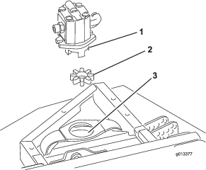
Note: Inspect spider hub for wear and replace if it is worn (Figure 2).
-
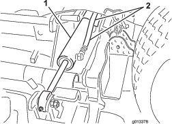
Disconnect the hydraulic hoses from the wing-deck-lift cylinders (Figure 3).
Important: When assembling the hydraulic hoses to the lift cylinders, ensure that the O–rings are in place and that the fittings are torqued to 23 to 26 N∙m (17 to 19 ft-lb).
-
Locate and unplug the cutting-unit wire harness from the traction unit wire harness (Figure 4).
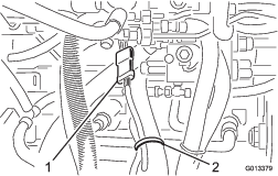
-
Remove any cable ties securing the cutting-unit wire harness to any traction unit components.
-
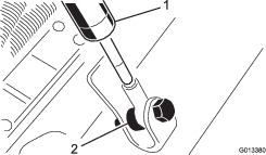
Remove the hairpin cotters securing the dampers to the cutting-unit lift arms (Figure 5).
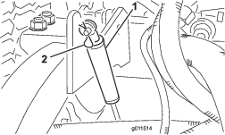
-
Remove the bolts, spacers, and flange nuts securing the opposite end of the dampers to the cutting unit (Figure 6).
Note: Make sure that the spacer is positioned in front of the damper-rod end when assembling to the cutting unit.
-
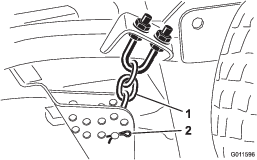
Remove the hair pin cotters and the clevis pins securing the height-of-cut chains to the rear of the cutting unit (Figure 7).
-
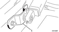
Remove the bolts, washers, and locknuts securing each lift arm mount to the castor-arm tubes (Figure 8).
Important: When assembling the lift arm mounts to the castor arm tubes, make sure they are positioned so that the slotted mounting holes are to the rear and the fasteners are torqued to (102 to 115 N∙m) 75 to 85 ft-lb.
-
Move the cutting unit away from the traction unit.
-
Slide the new cutting unit into position and mount it to the traction unit by reversing the procedure.
-
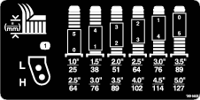
Verify the height-of-cut settings; refer to the Operator’s Manual.
-
Grease the cutting unit; refer to the Operator’s Manual.
-
Verify that the cutting-unit height sensors are set correctly; refer to the instructions for Part No. 119-5307.