Safety
Safety and Instructional Decals
 |
Safety decals and instructions are easily visible to the operator and are located near any area of potential danger. Replace any decal that is damaged or missing. |

Installation
Note: Lay out the harnesses on the machine to determine the mounting locations of the harness components. Use the included cable ties to retain any surplus cable. Also, if you need to shorten or lengthen a harness section, use the included wire splices. Heat the integrated heat-shrink tubing until it shrinks tight onto the wires.
Important: If you lengthen the harness, make sure to use the proper gauge of wire.
Preparing the Machine
-
Park the traction unit and the topdresser on a level surface and lower the attachments (if equipped).
-
Engage the parking brake, shut off the engine, and remove the key.
Installing the Kit on a ProPass Top Dresser
Installing the Switch Harness and the Switch on a Workman Utility Vehicle
-
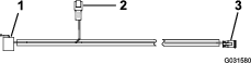
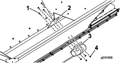
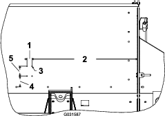
Route the switch harness shown in Figure 4 through the vehicle, starting at the front, along the existing harness.
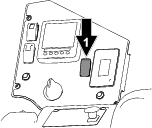
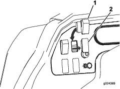
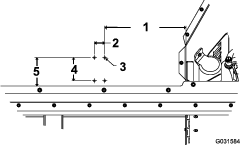
Note: The vibrator-harness connector should be in the rear of the vehicle near the high-flow hydraulics port (Figure 1).
-
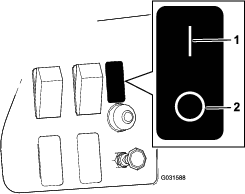
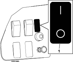
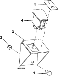
Insert the switch, with the rounded side up, into the hole in the dash panel and connect the harness to the switch (Figure 2 and Figure 4).
-
Secure the harness with cable ties, away from any sharp edges.
-
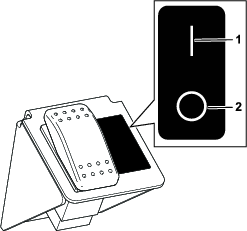
Place the decal on the dash next to the switch (Figure 3).
Installing the Power Harness
-
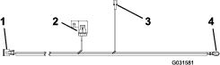
Connect the fuse-block connector (Figure 4) to the fuse block of the vehicle and install a 15 A fuse.
Note: If the fuse block is full, add a new fuse block, connect the fuse-block connector to the new fuse block, then add a 15 A fuse to the new fuse block.
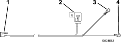
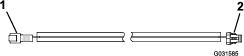
Note: As an option, you can connect the kit directly to the battery rather than to the fuse block of the vehicle; use the battery harness included with the kit (Figure 5).If you are using the optional battery harness, connect the positive terminal to the positive battery terminal.
-
Connect the grounding terminal to the ground block of the vehicle.
-
Plug the open connector (the switch-harness connector) on the power harness into the open connector (the power-harness connector) on the switch harness.
-
Secure the harness with cable ties, away from any sharp edges.
Installing the Vibrator
-
Drill 4 mounting holes (7 mm or 9/32 inch) on the side of the hopper. Refer to Figure 6 for the drilling dimensions.
Note: Locate 1 hole, then use the mounting plate as a template for drilling the remaining holes.
-
Secure the mounting plate and the vibrator to the hopper using 4 carriage bolts and 4 nuts as shown in Figure 7.
Note: Position the vibrator so that the cable is facing down.
-
Connect the vibrator harness to the vibrator.
-
Connect the switch harness to the other end of the vibrator harness.
Note: On a tow-behind machine, you can make the connection when attaching the top dresser to the traction unit.
-
Secure the harness with cable ties, away from any sharp edges.
Installing the Kit on an MH-400 Material Handler
Installing the Switch Harness and the Switch on a Tractor
Note: Lay out the harnesses on the machine to determine the mounting locations of the harness components. Use the included cable ties to retain any surplus cable. Also, if you need to shorten or lengthen a harness section, use the included wire splices. Heat the integrated heat-shrink tubing until it shrinks tight onto the wires.
Important: If you lengthen the harness, make sure to use the proper gauge of wire.
-
Route the wiring harness through the tractor.
Note: Make sure that the switch harness has enough length to reach the vibrator harness.
-
Remove a knockout plug from an available switch location on the dash.
If no switch locations are available, install the switch bracket as follows:
-
Find an empty space on the dash to accommodate the switch bracket, and drill 2 holes (7 mm or 9/32 inch) in the dash.
Note: Use the switch bracket as a guide for drilling the holes.
-
Mount the switch bracket to the dash using the 2 bolts and 2 flange nuts (Figure 9).
-
-
Insert the switch, with the rounded side up, into the hole in the dash or into the bracket.
-
Connect the switch harness to the switch (Figure 9 and Figure 11).
-
Place the decal next to the switch (Figure 9).
-
Secure the harness with cable ties, away from any sharp edges.
Installing the Power Harness
Install 1 of the power harnesses as follows:
-
To power the kit from the tractor fuse block, use the fuse-block harness Figure 10. Attach the fuse-block connector to the tractor fuse block and install a 15 A fuse.
Note: If the fuse block is full, add a new fuse block, connect the fuse-block connector to the new fuse block, then add a 15 A fuse to the new fuse block.
Note: You may need to change the terminal and/or the wire length, depending on the tractor model.
Important: If you lengthen the harness, make sure to use the proper gauge of wire.
To power the kit directly from the battery, use the battery harness (Figure 11).
Connect the positive terminal to the positive battery terminal.
-
Connect the grounding terminal to the ground block of the vehicle.
-
Plug the open connector (the switch-harness connector) on the power harness into the open connector (the power-harness connector) on the switch harness.
-
Secure the harness with cable ties, away from any sharp edges.
Installing the Vibrator
-
Drill 4 mounting holes (7 mm or 9/32 inch) on the side of the hopper. Refer to Figure 12 for the drilling dimensions.
Note: Locate 1 hole, then use the mounting plate as a template for drilling the remaining holes.
-
Secure the mounting plate and the vibrator to the vehicle using the 4 carriage bolts and 4 nuts as shown in Figure 13.
Note: Position the vibrator cable so that it is facing down.
-
Connect the vibrator harness to the vibrator.
Note: Route the vibrator harness so that it follows the hydraulic lines, as the MH-400 material handler can pivot upward.
-
Use cable ties to secure all the wires along the hydraulic lines all the way to the switch-harness connector.
Note: Ensure that the harness is kept away from any sharp edges.
-
Connect the switch harness to the other end of the vibrator harness.
Note: You can make the connection when attaching the material handler to the traction unit.
Installing the Kit on an MH-400 Material Handler with an Outcross 9060 Traction Unit
Parts needed for this procedure:
| Wire harness | 1 |
Installing the Wire Harness
Note: Following these instructions allows you to use the accessory switch that is already installed on the dashboard of the Outcross 9060 traction unit, wired through the 7-pin connection.
If the serial number of your MH-400 material handler is 400000000 or higher, plug the switch-harness connector on the kit harness into the MH-400 connector labeled SHAKER.
If the serial number of your MH-400 material handler is less than 400000000, modify the vibrator wire harness in the kit as follows:
-
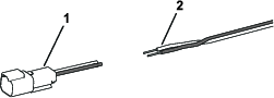
Cut off and discard the switch-harness connector and strip 10 mm (3/8 inch) of insulation off the wires (Figure 15).
-
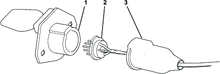
Access the 7-pin connector on the MH-400 material handler by pulling the boot back and removing the connector from the housing (Figure 16).
-
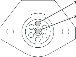
Loosen the screws in the pin 1 and pin 7 terminals (Figure 17).
-
Insert the wires through the small hole in the boot.
-
Install the black wire to the pin 1 terminal and the white wire to the pin 7 terminal (Figure 17).
-
Tighten the screws to secure the wires.
-
Assemble the 7-pin connector.
Installing the Vibrator
-
Drill 4 mounting holes (7 mm or 9/32 inch) on the side of the hopper. Refer to Figure 18 for the drilling dimensions.
Note: Locate 1 hole, then use the mounting plate as a template for drilling the remaining holes.
-
Secure the mounting plate and the vibrator to the vehicle using the 4 carriage bolts and 4 nuts as shown in Figure 19.
Note: Position the vibrator cable so that it is facing down.
-
Connect the vibrator harness to the vibrator.
Note: Route the vibrator harness so that it follows the hydraulic lines, as the MH-400 material handler can pivot upward.
-
Use cable ties to secure all the wires along the hydraulic lines all the way to the switch-harness connector.
Note: Ensure that the harness is kept away from any sharp edges.
-
Connect the switch harness to the other end of the vibrator harness.
Note: You can make the connection when attaching the material handler to the traction unit.