Installation
Mounting the Brush Brackets
Parts needed for this procedure:
| Left brush bracket | 1 |
| Right brush bracket | 1 |
| Flange head bolt (3/8 x 1 inch) | 2 |
| Bolt (M10 x 30 mm) | 2 |
| Level adjustment screw | 2 |
| Jam nut (5/16 inch) | 2 |
| Lock nut (5/16 inch) | 2 |
| Brush spring | 2 |
| Brush rod | 2 |
| Bolt (M6 x 40 mm) | 4 |
| Spacer | 4 |
| Locknut (M6) | 4 |
-
Position the machine on a level surface, engage the parking brake, remove the key (if equipped), disconnect the battery, and shut off the machine.
-
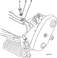
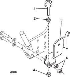
Remove the bolt and washer securing the left end of the front frame to the tab on top of the cutting unit (Figure 1).
-
Mount the left brush bracket to the front frame and tab as follows:
-
On Flex 1800/2100 models, secure the brush bracket to the front frame and tab with a flange head bolt (3/8 x 1 inch) as shown in Figure 2.
-
On Flex 18/21 models, secure the brush bracket to the front frame and tab with a new bolt (M10 x 30mm) and the washer that was previously removed (Figure 2).
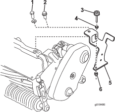
Note: The bracket is to be positioned so the hole in the bottom is to the front. The bracket should fit over the end of the front frame and tab.
-
-
Loosely mount the level adjustment screw to the brush bracket with a jam nut (5/16 inch) and a locknut (5/16 inch) as shown in Figure 2.
-
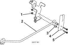
Mount a brush spring and brush rod to the brush bracket with (2) bolts (M6 x 40 mm), spacers and locknuts (M6) as shown in Figure 3.
Note: Ensure that the brush spring is mounted with the bump to the outside. The brush rod should be centered in the brush spring when it is rotated upward, into the storage position.
-
Repeat this procedure on the opposite side of the machine.
Note: There will be leftover locknuts.
Mounting the Brush Brackets
Parts needed for this procedure:
| Left brush bracket | 1 |
| Right brush bracket | 1 |
| Bolts (fully threaded, 5/16 x 1-1/2 inches) | 4 |
| Locknut (5/16 inch) | 4 |
| Level adjustment screw | 2 |
| Jam nut (5/16 inch) | 2 |
| Lock nut (5/16 inch) | 2 |
| Brush spring | 2 |
| Brush rod | 2 |
| Bolt (M6 x 40 mm) | 4 |
| Spacer | 4 |
| Locknut (M6) | 4 |
-
Position the machine on a level surface, engage the parking brake, remove the key (if equipped) and shut off the machine.
-
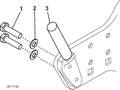
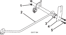
Remove the 2 bolts and washers securing the grass basket mounting rod to the left side plate (Figure 4). Discard the bolts but retain the washers.
-
Secure the grass basket mounting rod to the left side plate with 2 new, fully threaded bolts (5/16 x 1-1/2 inches) and the 2 washers that were previously removed (Figure 5).
-
Insert the left brush bracket onto the bolt and secure it with 2 locknuts (5/16 inch) as shown in Figure 5.
Note: The bracket is to be positioned so that the hole in the bottom is to the front.
-
Loosely mount the level adjustment screw to the brush bracket with a jam nut (5/16 inch) and a locknut (5/16 inch) as shown in Figure 5.
-
Mount a brush spring and brush rod to the brush bracket with 2 bolts (M6 x 40 mm), spacers, and locknuts (M6) as shown in Figure 6.
Note: Ensure that the brush spring is mounted with the bump to the outside. The brush rod should be centered in the brush spring when it is rotated upward, into the storage position.
-
Repeat this procedure on the opposite side of the machine.
Mounting the Brush
Parts needed for this procedure:
| Brush | 1 |
| Brush tab | 2 |
| Bolt (M8 x 60 mm) | 4 |
| Washer | 4 |
| Locknut (M8) | 4 |
| Flange-head bolt (M6 x 20 mm) | 4 |
| Flange nut (M6) | 4 |
-
If the brush is going to be used on an 18 inch cutting unit, measure and cut 1-1/2 inches off each end of the brush.
-
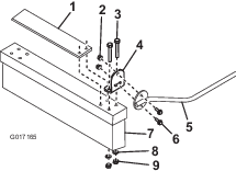
Mount a brush tab to each end of the brush with 2 bolts (M8 x 60 mm), washers, and locknuts (M8). Position the tabs as shown in Figure 7. Use the outer holes for installation on a 21 inch cutting unit and the inner holes for 18 inch cutting unit.
Note: The brush bristles are cut at an angle. Mount the brush so the longer bristles are closest to the machine when mowing.
-
Secure a brush rod mounting bracket to each brush tab with 2 flange head bolts (M6 x 20 mm) and flange nuts (M6) (Figure 7).
-
Adjust the operating height of the brush and level it by loosening the jam nuts, rotating the adjustment screws to the desired position and tightening the jam nuts.
Note: The ends of the brush bristles should be flat on the ground during the mowing operation. If the brush hops during operation, rotate the brush so that only the front bristles touch the surface and the rear bristles are less than 1/2 inch above the surface.
-
Rotate the brush upward and secure the rods into the brush springs when the brush is not required.