| Maintenance Service Interval | Maintenance Procedure |
|---|---|
| Before each use or daily |
|
Introduction
This machine is a ride-on, reel-blade lawn mower intended to be used by professional operators in commercial applications. It is primarily designed for cutting grass on well-maintained turf. Using this product for purposes other than its intended use could prove dangerous to you and bystanders.
Read this information carefully to learn how to operate and maintain your product properly and to avoid injury and product damage. You are responsible for operating the product properly and safely.
Visit www.Toro.com for more information, including safety tips, training materials, accessory information, help finding a dealer, or to register your product.
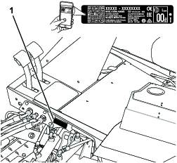
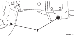
Whenever you need service, genuine Toro parts, or additional information, contact an Authorized Service Dealer or Toro Customer Service and have the model and serial numbers of your product ready. Figure 1 identifies the location of the model and serial numbers on the product. Write the numbers in the space provided.
Important: With your mobile device, you can scan the QR code (if equipped) on the serial number decal to access warranty, parts, and other product information.
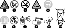
This manual identifies potential hazards and has safety messages identified by the safety-alert symbol (Figure 2), which signals a hazard that may cause serious injury or death if you do not follow the recommended precautions.

This manual uses 2 words to highlight information. Important calls attention to special mechanical information and Note emphasizes general information worthy of special attention.
This product complies with all relevant European directives. For details, please see the separate product specific Declaration of Conformity (DOC) sheet.
It is a violation of California Public Resource Code Section 4442 or 4443 to use or operate the engine on any forest-covered, brush-covered, or grass-covered land unless the engine is equipped with a spark arrester, as defined in Section 4442, maintained in effective working order or the engine is constructed, equipped, and maintained for the prevention of fire.
The enclosed engine owner’s manual is supplied for information regarding the US Environmental Protection Agency (EPA) and the California Emission Control Regulation of emission systems, maintenance, and warranty. Replacements may be ordered through the engine manufacturer.
Warning
CALIFORNIA
Proposition 65 Warning
Diesel engine exhaust and some of its constituents are known to the State of California to cause cancer, birth defects, and other reproductive harm.
Battery posts, terminals, and related accessories contain lead and lead compounds, chemicals known to the State of California to cause cancer and reproductive harm. Wash hands after handling.
Use of this product may cause exposure to chemicals known to the State of California to cause cancer, birth defects, or other reproductive harm.
Safety
This machine has been designed in accordance with EN ISO 5395 (when you complete the setup procedures) and ANSI B71.4-2017.
General Safety
This product is capable of amputating hands and feet and of throwing objects.
-
Read and understand the contents of this Operator’s Manual before starting the engine.
-
Use your full attention while operating the machine. Do not engage in any activity that causes distractions; otherwise, injury or property damage may occur.
-
Do not put your hands or feet near moving components of the machine.
-
Do not operate the machine without all guards and other safety protective devices in place and functioning properly on the machine.
-
Keep children, bystanders, and pets out of the operating area. Never allow children to operate the machine.
-
Shut off the engine, remove the key, wait for all movement to stop before you leave the operator’s position. Allow the machine to cool before adjusting, servicing, cleaning, or storing it.
Improperly using or maintaining this machine can result in injury.
To reduce the potential for injury, comply with these safety instructions
and always pay attention to the safety-alert symbol  , which means
Caution, Warning, or Danger—personal safety instruction. Failure
to comply with these instructions may result in personal injury or
death.
, which means
Caution, Warning, or Danger—personal safety instruction. Failure
to comply with these instructions may result in personal injury or
death.
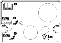
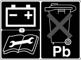
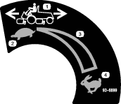
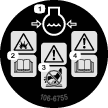
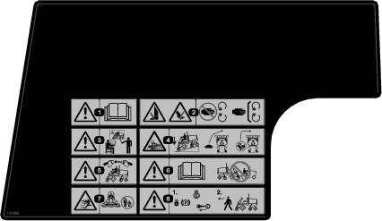
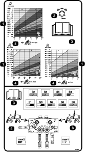
Safety and Instructional Decals
|
Safety decals and instructions are easily visible to the operator and are located near any area of potential danger. Replace any decal that is damaged or missing. |


Setup
Note: Determine the left and right sides of the machine from the normal operating position.
Checking Fluid Levels
Before starting the engine for the first time, check the following fluid levels:
-
Engine oil
Refer to Checking the Engine Oil.
-
Engine coolant
Refer to Checking the Cooling System.
-
Hydraulic oil
Refer to Checking the Hydraulic Fluid.
-
Rear axle lubricant
Refer to Checking the Rear Axle Lubricant.
Installing the Cutting Units
Parts needed for this procedure:
| Lift chain | 7 |
| Chain bracket | 7 |
| U-bolt | 7 |
| Nut | 14 |
| Screw | 7 |
| Washer | 7 |
| Nut | 7 |
| Large O-ring | 7 |
| Kickstand | 1 |
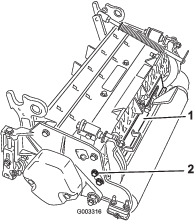
Removing the Tipper Assemblies
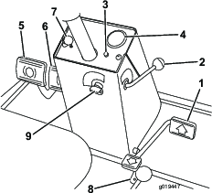
Remove the tipper assemblies (if so equipped) from the number 1, number 2, and number 3 lift arms to avoid interference with the carrier frames of the cutting units.
-
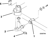
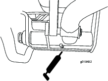
Remove the locknut and the washer securing the pivot rod to the number 2 lift arm (Figure 3). Remove the pivot rod and spring from the lift arm. Repeat the procedure on the number 1 and number 3 lift arms.
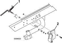
Note: The tipper bracket with the roller and the tipper support brackets are not required when operating the DPA cutting units (Figure 3).
-
Disconnect the lift chains from the cutting units, if attached.
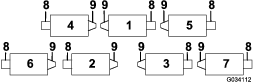
Mounting the Lift Brackets and Chains
Mount a chain bracket to each lift arm with a U-bolt and 2 nuts. Position the brackets as follows:
Note: Refer to Figure 4 to determine the lift arm number being described.
-
On lift arm numbers 1, 4, and 5, position the chain brackets and U-bolts 38.1 cm (15 inches) behind the center line of the pivot knuckle (Figure 5).
-
On lift arm numbers 1 and 5 the brackets should be rotated to the right 10 degrees from vertical (Figure 5).
-
On lift arm number 4 the bracket should be rotated to the left 10 degrees from vertical (Figure 5).
-
On lift arm numbers 2 and 3, position the brackets and U-bolts 38.1 cm (15 inches) behind the center line of the pivot knuckle (Figure 6).
Note: Rotate the brackets 45 degrees to the outboard side of the machine.
-
On lift arm number 6 and number 7, position the brackets and U-bolts 36.8 cm (14.5 inches) behind the center line of the pivot knuckle (Figure 7).
Note: Rotate the brackets 10 degrees to the outboard side of the machine.
-
Tighten all the U-bolt nuts to 52 to 65 N∙m (38 to 48 ft-lb).
-
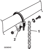
Mount a lift chain to each chain bracket with a screw, a washer, and a nut, positioning them as shown in Figure 8.
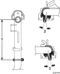
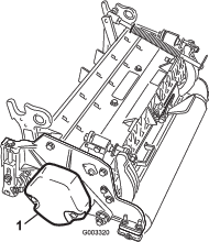
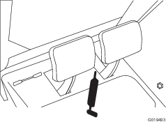
Using the Kickstand
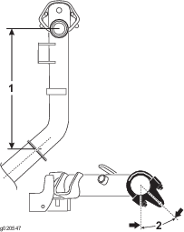
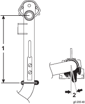
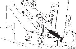
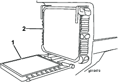
Whenever the cutting unit has to be tipped to expose the bedknife/reel, prop up the rear of the cutting unit with the kickstand to make sure that the nuts on the back end of the bedbar adjusting screws are not resting on the work surface (Figure 9).
Adjusting the Rear Shield
Under most conditions, best dispersion is attained when the rear shield is closed (front discharge). When conditions are heavy or wet, the rear shield may be opened.
To open the rear shield (Figure 10), loosen the cap screw securing the shield to the left side plate, rotate the shield to the open position, and tighten the cap screw.
Mounting the Counterweights
All cutting units are shipped with the counterweight mounted to the left end of the cutting unit. Use the following diagram to determine the position of the counterweights and reel motors.
Note: Some traction units have only 5 cutting units.
-
On cutting unit numbers 2, 4, and 6, remove the 2 cap screws securing the counterweight to the left end of the cutting unit.
Note: Remove the counterweight (Figure 12).
-
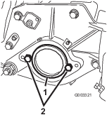
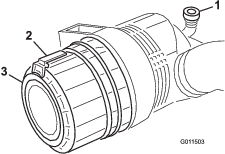
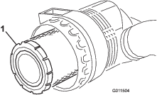
On the right end of the cutting unit, remove the plastic plug from the bearing housing (Figure 13).
-
Remove the 2 cap screws from the right side plate (Figure 13).
-
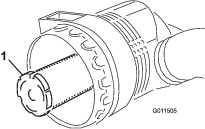
Install the counterweight to the right end of the cutting unit with the 2 screws previously removed.
-
Loosely install the 2 reel motor mounting cap screws to the left side plate of the cutting unit (Figure 13).
Installing the Cutting Units
Figure 14 shows the orientation of the hydraulic drive motor for each of the cutting unit locations. For any of the locations requiring the motor to be mounted on the right end of the cutting unit, install a counter weight on the left end of the cutting unit. For the locations requiring the motor to be mounted on the left end, install a counter weight on the right end of the cutting unit.
Note: The counterweight mounting cap screws are shipped installed on the right bearing housing of the cutting units. The cap screws on the left bearing housing are to be used for securing the hydraulic motor.
-
Remove the cutting units from the cartons. Assemble and adjust them per the cutting unit Operator's Manual.
-
Remove the protective plugs from each end of the cutting unit.
-
Lubricate and install a large O-ring into bearing housing groove on each end of cutting unit (Figure 15 & Figure 18).
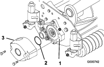
Note: Before installing the cutting unit motors or counterweights, lubricate the internal splines of the cutting unit reel shafts with grease.
-
Install a counter weight onto the appropriate end of each cutting unit with the cap screws provided (Figure 15).
-
Thoroughly grease the cutting unit reel bearings prior to installation on the traction unit. Grease should be evident at the inboard reel seals; refer to the cutting unit Operator's Manual for greasing procedure.
-
Insert a thrust washer onto the horizontal shaft of the pivot knuckle as shown in (Figure 16).
-
Insert the horizontal shaft of the pivot knuckle into the mounting tube of the carrier frame (Figure 16).
-
Secure the pivot knuckle to the carrier frame with a thrust washer, a flat washer, and a flange-head cap screw (Figure 16).
-
Insert a thrust washer onto vertical shaft of pivot knuckle (Figure 16).
-
If removed, insert the vertical shaft of the pivot knuckle into lift arm pivot hub (Figure 16). Guide the pivot knuckle in place between the two rubber centering bumpers in the under side of the lift arm steering plate.
-
Insert the lynch pin into the cross hole on the pivot knuckle shaft (Figure 16).
-
Remove nut securing turf compensation spring mounting bracket to cutting unit stabilizer ear (Figure 17). Install the tipper chain onto the cap screw and secure it with the nut that you previously removed.
-
Mount the motor to the drive end of the cutting unit and secure it with 2 cap screws (Figure 18).
Note: If fixed cutting unit position is required, insert the steering locking pin into the pivot knuckle mounting hole (Figure 16).
-
Hook the spring wire around the bottom of the steering locking pin (Figure 16).
Turf-Compensation Settings
The turf-compensation spring transfers the weight from the front to the rear roller. This helps to reduce a wave pattern in the turf, also known as marcelling or bobbing.
Important: Make spring adjustments with the cutting unit mounted to the traction unit, pointing straight ahead and lowered to the shop floor.
-
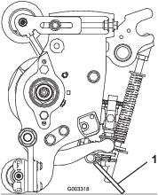
Make sure that the hairpin cotter is installed in the rear hole in the spring rod (Figure 19).
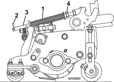
-
Tighten the hex nuts on the front end of the spring rod until the compressed length of the spring is 15.9 cm (6.25 inches); refer to Figure 19.
Note: When operating on rough terrain decrease the spring length by 12.7 mm (0.5 inch). Ground following will be slightly shorter.
Note: You must reset the turf-compensation setting if the HOC setting or the aggressiveness-of-cut setting is changed.
Making Alternate Cutting Unit Adjustments
The factory sets the tractor appropriately for most fairway mowing applications. Several adjustments for fine-tuning the machine for particular applications are included in the Cutting Unit Maintenance section as follows:
-
Adjusting the cutting unit lowering rate
Adjusts the speed at which the cutting units lower.
-
Adjusting the lifted height of the outer front cutting units
Adjusts the turnaround height of the outer front cutting units to provide greater clearance on contoured fairways.
-
Adjusting the travel of the front three cutting units
Adjusts the downward travel of the front three cutting units to allow for highly contoured fairways.
Adding Rear Ballast
Parts needed for this procedure:
| Calcium chloride (obtain separately) | 45 kg (100 lb) |
| Rear weight kit, part number 104-1478 (obtain separately) | 1 |
To comply with EN ISO 5395 and ANSI B71.4-2017, add 45 kg (100 lb) of calcium chloride ballast to the rear wheels and install the rear weight kit (Part No. 104-1478).
Important: If a puncture occurs in a tire with calcium chloride, remove the machine from the turf area as quickly as possible. To prevent possible damage to turf, immediately soak the affected area with water.
Applying the CE Decals
Parts needed for this procedure:
| Warning decal | 1 |
| CE decal | 1 |
| Year of production decal | 1 |
On machines requiring CE compliance, apply the year of production decal (Part No. 133-5615) near the serial plate, the CE decal (Part No. 93-7252) near the hood lock, and the CE warning decal (Part No. 115-2046) over the standard warning decal (Part No. 115-2045).
Product Overview
Traction Pedal
The traction pedal (Figure 20) controls forward and reverse operation. Press the top of the pedal to move the machine forward and the bottom of the pedal to move the machine backward. Ground speed is determined by how far you press the pedal. For maximum ground speed, fully press the pedal while the throttle is in the FAST position.
To stop the machine, reduce your foot pressure on the traction pedal and allow it to return to the center position.
Forward Speed Limiter
Preset the forward speed limiter (Figure 20) to limit the amount the traction pedal can be pressed in the forward direction to maintain a constant mowing speed.
Red Diagnostic Light
The red diagnostic light (Figure 20), located on steering tower, is used to convey several different messages. While starting the machine, the light illuminates when the glow plugs are on.
If the light blinks during operation, it may indicate any of the following:
-
The machine is being operated faster than the maximum speed value initially programmed into the ECU.
-
An electrical malfunction has been detected (open or shorted output.
-
A hydraulic leak has been detected (Only if Turfdefender leak detector is installed on machine)
-
A communications error has been detected (Only if Turfdefender leak detector is installed on machine)
Key Switch
The key switch (Figure 20) has 3 positions: OFF, ON/PREHEAT, and START.
Speedometer
The speedometer (Figure 20) indicates the ground speed at which the machine is traveling.
Brake Pedals
Two brake pedals (Figure 20) operate individual wheel brakes for turning assistance, parking, and to aid in obtaining better sidehill traction. Locking pin connects the pedals for parking brake operation and transport.
Parking Brake Latch
A knob on the left side of the console actuates the parking brake latch (Figure 20). To engage the parking brake, connect the pedals with the locking pin, push down on both pedals, and pull the parking brake latch out. To release the parking brake, press both pedals until the parking brake latch retracts.
Reverse Speed Limiter
Adjust the screw (Figure 20) to limit the amount that you can press the traction pedal in the rearward direction to limit speed.
Lower Mow/Raise Control Lever
This lever (Figure 21) raises and lowers the cutting units and also starts and stops the reels when you enable the reels in the mow mode. You cannot lower the cutting units when the mow/transport lever is in the transport position.
Fuel Gauge
The fuel gauge (Figure 21) indicates the level of fuel in the tank.
Engine Oil Pressure Warning Light
This light (Figure 21) indicates dangerously low engine oil pressure.
Throttle Control
Move the control (Figure 21) forward to increase engine speed, rearward to decrease speed.
Engine Coolant Temperature Warning Light
The light (Figure 21) illuminates and the engine shuts down when the coolant reaches a dangerously high temperature.
Glow Plug Indicator Light
When the indicator light (Figure 21) is lit, it indicates that the glow plugs are on.
Enable/Disable Switch
Use the enable/disable switch in conjunction with the lower mow/raise control lever to operate the cutting units (Figure 21).
Hour Meter
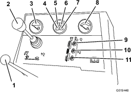
The hour meter (Figure 22) shows the total hours that the machine has been operated.

Backlap Knobs
The backlap knobs (Figure 23) are used in conjunction with the lower mow/raise control lever for backlapping the cutting units. Refer to Backlapping the Cutting Units.
Reel Speed Controls
Seat Controls
The seat-adjusting lever (Figure 25) allows you to adjust the seat forward and rearward. The seat-adjusting knob (Figure 25 adjusts the seat for your weight. To adjust the seat forward and rearward, pull the lever on the left side of the seat assembly outward. After moving the seat to the desired location, release the lever to lock the seat into position. To adjust the seat for your weight, turn the spring tension knob—clockwise to increase the spring tension, counterclockwise to decrease the spring tension.
Green Diagnostic Light
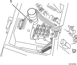
The machine is equipped with a diagnostic light that indicates if the electronic controller is functioning correctly. The green diagnostic light (Figure 26) is located under the control panel, next to the fuse block. When the electronic controller is functioning correctly and the key is moved to the ON position, the controller diagnostic light illuminates. The light blinks if the controller detects a malfunction in the electrical system. The light stops blinking and automatically resets when you turn the key to the OFF position.
When the controller diagnostic light blinks, one of the following problems has been detected by the controller:
-
One of the outputs has been shorted.
-
One of the outputs is open circuited.
Using the diagnostic display, determine which output is malfunctioning, refer to Checking the Interlock Switches.
If the diagnostic light is not illuminated when the key switch is in the ON position, this indicates that the electronic controller is not operating. Possible causes include the following:
-
Loop-back is not connected.
-
The light is burned out.
-
Fuses are blown.
-
There is no battery power.
Check the electrical connections, input fuses, and diagnostic light bulb to determine the malfunction. Ensure that the loop-back connector is secured to the wire harness connector.
Diagnostic ACE Display (Optional)
The machine is equipped with an electronic controller which controls most machine functions. The controller determines what function is required for various input switches (i.e. seat switch, key switch, etc.) and turns on the outputs to actuate solenoids or relays for the requested machine function.
For the electronic controller to control the machine as desired, each of the input switches, output solenoids, and relays must be connected and functioning properly.
The Diagnostic ACE display is a tool to help the user verify correct electrical functions of the machine.
Note: Specifications and design are subject to change without notice.
| Width of cut | 338 cm (133 inches) |
| Overall width—transport | 226 cm (89 inches) |
| Overall width—operational | 279 cm (110 inches) |
| Overall length | 305 cm (120 inches) |
| Height with ROPS installed | 213 cm (84 inches) |
| Weight* | 1792 kg (3,950 lb) |
| * With 5 blade cutting units and full fluid levels. | |
Attachments/Accessories
A selection of Toro approved attachments and accessories is available for use with the machine to enhance and expand its capabilities. Contact your Authorized Service Dealer or authorized Toro distributor or go to www.Toro.com for a list of all approved attachments and accessories.
To ensure optimum performance and continued safety certification of the machine, use only genuine Toro replacement parts and accessories. Replacement parts and accessories made by other manufacturers could be dangerous, and such use could void the product warranty.
Operation
Before Operation
Before Operation Safety
General Safety
-
Never allow children or untrained people to operate or service the machine. Local regulations may restrict the age of the operator. The owner is responsible for training all operators and mechanics.
-
Become familiar with the safe operation of the equipment, operator controls, and safety signs.
-
Always shut off the engine, remove the key, wait for all moving parts to stop, and allow the machine to cool before adjusting, servicing, cleaning, or storing the machine.
-
Know how to stop the machine and shut off the engine quickly.
-
Do not operate the machine without all guards and other safety protective devices in place and functioning properly on the machine.
-
Before mowing, always inspect the machine to ensure that the cutting units are in good working condition.
-
Inspect the area where you will use the machine and remove all objects that the machine could throw.
Fuel Safety
-
Use extreme care in handling fuel. It is flammable and its vapors are explosive.
-
Extinguish all cigarettes, cigars, pipes, and other sources of ignition.
-
Use only an approved fuel container.
-
Do not remove the fuel cap or fill the fuel tank while the engine is running or hot.
-
Do not add or drain fuel in an enclosed space.
-
Do not store the machine or fuel container where there is an open flame, spark, or pilot light, such as on a water heater or other appliance.
-
If you spill fuel, do not attempt to start the engine; avoid creating any source of ignition until the fuel vapors have dissipated.
Performing Daily Maintenance
Before starting the machine each day, perform the Each Use/Daily procedures listed in .
Filling the Fuel Tank
Fuel tank capacity: 57 liters (15 US gallons)
Use only clean, fresh diesel fuel or biodiesel fuels with low (<500 ppm) or ultra low (<15 ppm) sulfur content. The minimum cetane rating should be 40. Purchase fuel in quantities that can be used within 180 days to ensure fuel freshness.
Use summer grade diesel fuel (No. 2-D) at temperatures above -7° C (20° F) and winter grade (No. 1-D or No. 1-D/2-D blend) below that temperature. Use of winter grade fuel at lower temperatures provides lower flash point and cold flow characteristics which will ease starting and reduce fuel filter plugging.
Use of summer grade fuel above -7° C (20° F) will contribute toward longer fuel pump life and increased power compared to winter grade fuel.
Important: Do not use kerosene or gasoline instead of diesel fuel. Failure to observe this caution will damage the engine.
Biodiesel Ready
This machine can also use a biodiesel blended fuel of up to B20 (20% biodiesel, 80% petrodiesel). The petrodiesel portion should be low or ultra low sulfur. Observe the following precautions:
-
The biodiesel portion of the fuel must meet specification ASTM D6751 or EN14214.
-
The blended fuel composition should meet ASTM D975 or EN590.
-
Painted surfaces may be damaged by biodiesel blends.
-
Use B5 (biodiesel content of 5%) or lesser blends in cold weather.
-
Monitor seals, hoses, gaskets in contact with fuel as they may be degraded over time.
-
Fuel filter plugging may be expected for a time after converting to biodiesel blendsd.
-
Contact your distributor if you wish for more information on biodiesel.
-
Park the machine on a level surface, lower the cutting units, shut off the engine, engage the parking brake, and remove the key.
-
Using a clean rag, clean area around the fuel-tank cap.
-
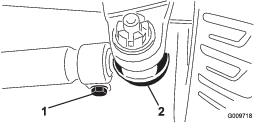
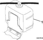
Remove the cap from the fuel tank (Figure 27).
-
Fill the tank with fuel until the level is to the bottom of the filler neck.
-
Install the fuel-tank cap tightly after filling the tank.
Note: If possible, fill the fuel tank after each use. This minimizes possible buildup of condensation inside the fuel tank.
During Operation
During Operation Safety
General Safety
-
The owner/operator can prevent and is responsible for accidents that may cause personal injury or property damage.
-
Wear appropriate clothing, including eye protection; long pants; substantial, slip-resistant footwear; and hearing protection. Tie back long hair and do not wear loose clothing or loose jewelry.
-
Do not operate the machine while ill, tired, or under the influence of alcohol or drugs.
-
Use your full attention while operating the machine. Do not engage in any activity that causes distractions; otherwise, injury or property damage may occur.
-
Before you start the engine, ensure that all drives are in neutral, the parking brake is engaged, and you are in the operating position.
-
Do not carry passengers on the machine and keep bystanders and pets away from the machine during operation.
-
Operate the machine only in good visibility to avoid holes or hidden hazards.
-
Avoid mowing on wet grass. Reduced traction could cause the machine to slide.
-
Keep your hands and feet away from the cutting units.
-
Look behind and down before backing up to be sure of a clear path.
-
Use care when approaching blind corners, shrubs, trees, or other objects that may obscure your vision.
-
Stop the cutting units whenever you are not mowing.
-
Slow down and use caution when making turns and crossing roads and sidewalks with the machine. Always yield the right-of-way.
-
Never run an engine in an area where exhaust gasses are enclosed.
-
Never leave a running machine unattended.
-
Before leaving the operating position (including to empty the catchers or to unclog the cutting units), do the following:
-
Park the machine on level ground.
-
Disengage the cutting units and lower the attachments.
-
Engage the parking brake.
-
Shut off the engine and remove the key.
-
Wait for all moving parts to stop.
-
-
Operate the machine only in good visibility and appropriate weather conditions. Do not operate the machine when there is the risk of lightning.
Rollover Protection System (ROPS) Safety
-
Do not remove any of the ROPS components from the machine.
-
Ensure that the seat belt is attached and that you can release it quickly in an emergency.
-
Always wear your seat belt.
-
Check carefully for overhead obstructions and do not contact them.
-
Keep the ROPS in safe operating condition by thoroughly inspecting it periodically for damage and keeping all the mounting fasteners tight.
-
Replace all damaged ROPS components. Do not repair or alter them.
Slope Safety
-
Slopes are a major factor related to loss of control and rollover accidents, which can result in severe injury or death. You are responsible for safe slope operation. Operating the machine on any slope requires extra caution.
-
Evaluate the site conditions to determine if the slope is safe for machine operation, including surveying the site. Always use common sense and good judgment when performing this survey.
-
Review the slope instructions, listed below, for operating the machine on slopes. Before you operate the machine, review the site conditions to determine whether you can operate the machine in the conditions on that day and at that site. Changes in the terrain can result in a change in slope operation for the machine.
-
Avoid starting, stopping, or turning the machine on slopes. Avoid making sudden changes in speed or direction. Make turns slowly and gradually.
-
Do not operate a machine under any conditions where traction, steering, or stability is in question.
-
Remove or mark obstructions such as ditches, holes, ruts, bumps, rocks, or other hidden hazards. Tall grass can hide obstructions. Uneven terrain could overturn the machine.
-
Be aware that operating the machine on wet grass, across slopes, or downhill may cause the machine to lose traction.
-
Use extreme caution when operating the machine near drop-offs, ditches, embankments, water hazards, or other hazards. The machine could suddenly roll over if a wheel goes over the edge or the edge caves in. Establish a safety area between the machine and any hazard.
-
Identify hazards at the base of the slope. If there are hazards, mow the slope with a pedestrian-controlled machine.
-
If possible, keep the cutting units lowered to the ground while operating on slopes. Raising the cutting units while operating on slopes can cause the machine to become unstable.
-
Starting the Engine
-
Sit on the seat, keep your foot off the traction pedal so that it is in NEUTRAL, engage the parking brake, set the engine-speed switch to the SLOW position, and ensure that the Enable/Disable switch is in the DISABLE position.
-
Turn the key to the ON/PREHEAT position. An automatic timer controls the preheat for approximately 6 seconds.
-
When the glow indicator dims, turn the key to the START position. Release the key immediately when the engine starts and allow it to return to the RUN position. Allow the engine to warm up (without load), then move the throttle control to the desired position.
Crank the engine for no longer than 15 seconds. Release the key when the engine starts. If additional preheat is required, turn the key to the OFF position and then to the ON/PREHEAT position. Repeat the process as required.
Shutting Off the Engine
Move the throttle control to the IDLE position, move the reel drive switch to DISENGAGE, and rotate the key to the OFF position.
Note: Remove the key to prevent accidental starting.
Important: Allow the engine to idle for 5 minutes before shutting it off after a full load operation. Failure to do so may lead to turbocharger trouble.
Note: Lower the cutting units to the ground. This relieves pressure from the lift circuit and eliminates the risk of the cutting units accidentally lowering to the ground.
Bleeding the Fuel System
-
Park the machine on a level surface, lower the cutting units, shut off the engine, engage the parking brake, and remove the key.
-
Ensure that the fuel tank is at least half full.
-
Unlatch and raise the hood.
-
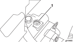
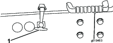
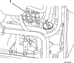
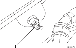
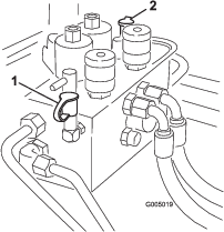
Open the vent plug on the fuel filter/water separator (Figure 28).
-
Turn the key to the ON position. The electric fuel pump will begin operation, thereby forcing air out around the vent plug. Leave the key in the ON position until a solid stream of fuel flows out around the plug. Tighten the plug and turn the key to the OFF position.
-
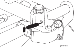
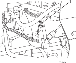
Open the air bleed screw on the fuel injection pump (Figure 29).
-
Turn the key to the ON position. The electric fuel pump will begin operation, thereby forcing air out around air bleed screw. Leave the key in the ON position until a solid stream of fuel flows out around the screw. Tighten the screw and turn key to the OFF position.
Note: Normally, the engine should start after you follow the above procedure. However, if the engine does not start, air may be trapped between the injection pump and the injectors; refer to Bleeding Air from the Injectors.
Checking the Interlock Switches
The purpose of the interlock switches is to prevent the engine from cranking or starting unless the traction pedal is in the NEUTRAL position, the Enable/Disable switch is in the DISABLE position, and the Lower Mow/Raise control is in the NEUTRAL position. In addition, the engine should shut off when you press the traction pedal while you are off the seat or if the parking brake is engaged.
Caution
If the safety-interlock switches are disconnected or damaged, the machine could operate unexpectedly, causing personal injury.
-
Do not tamper with the interlock switches.
-
Check the operation of the interlock switches daily and replace any damaged switches before operating the machine.
Verifying the Interlock-Switch Function
| Maintenance Service Interval | Maintenance Procedure |
|---|---|
| Before each use or daily |
|
-
Park the machine on a level surface, lower the cutting units, shut off the engine, engage the parking brake, and remove the key.
-
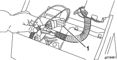
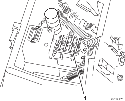
Open the control panel cover. Locate the wire harness and the loop-back connector. Carefully unplug the loop-back connector from the harness connector (Figure 30).
-
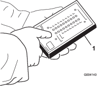
Connect the Diagnostic ACE display connector to the harness connector (Figure 31). Make sure that the correct overlay decal is positioned on Diagnostic ACE display.
-
Turn the key to the ON position, but do not start the machine.
Note: The red text on the overlay decal refers to input switches and the green text refers to outputs.
-
The “inputs displayed” LED, on lower right column of the Diagnostic ACE, should be illuminated. If “outputs displayed” LED is illuminated, press and release the toggle button on the Diagnostic ACE to change the LED to “inputs displayed”. Do not hold the button down.
-
The Diagnostic ACE will illuminate the LED associated with each of the inputs when that input switch is closed.
Individually, change each of the switches from open to closed (i.e., sit on seat, engage traction pedal, etc.), and note that the appropriate LED on Diagnostic ACE will blink on and off when corresponding switch is closed. Repeat on each switch that is possible to be changed by hand.
-
If switch is closed and appropriate LED does not turn on, check all wiring and connections to switch and/or check switches with an ohm meter. Replace any damaged switches and repair any damaged wiring.
The Diagnostic ACE also has the ability to detect which output solenoids or relays are turned on. This is a quick way to determine if a machine malfunction is electrical or hydraulic.
Verifying the Output Function
-
Park the machine on a level surface, lower the cutting units, shut off the engine, engage the parking brake, and remove the key.
-
Open the control panel cover. Locate the wire harness and connectors near the controller. Carefully unplug the loop-back connector from the harness connector.
-
Connect the Diagnostic ACE connector to the harness connector. Make sure that the correct overlay decal is positioned on the Diagnostic ACE.
-
Turn the key to the ON position, but do not start the machine.
Note: The red text on the overlay decal refers to input switches and the green text refers to outputs.
-
The “outputs displayed” LED, on lower right column of Diagnostic ACE, should be illuminated. If “inputs displayed”; LED is illuminated, press the toggle button on the Diagnostic ACE to change the LED to “outputs displayed.”
Note: It may be necessary to toggle between “inputs displayed” and “outputs displayed” several times to do the following step. To toggle back and forth, press toggle button once. This may be done as often as required. Do not hold the button.
-
Sit on the seat and attempt to operate the desired function of the machine. The appropriate output LEDs should illuminate to indicate that the ECU is turning on that function. (Refer to Hydraulic Solenoid Valve Functions to be certain of the specified output LEDs.)
Note: If any output LED is blinking, this indicates an electrical problem with that OUTPUT. Repair/replace defective electrical parts immediately. To reset a blinking LED, turn the key switch “Off”, then back “On” and clear the controllers fault memory; refer to Fault Memory and Retrieval.
If no output LEDs are blinking, but the correct output LEDs do not illuminate, verify that the required input switches are in the necessary positions to allow that function to occur. Verify correct switch function.
If the output LEDs are on as specified, but the machine does not function properly, this indicates a non-electrical problem. Repair as necessary.
Note: Due to electrical system constraints, the output LEDs for “Start”, “Preheat” and “ETR/ALT” may not blink even though an electrical problem may exist for those functions. If the machine problem appears to be with one of these functions, be certain to check the electrical circuit with a volt/ohm meter to verify that no electrical problem exists to these functions.
If each input switch is in the correct position and functioning correctly, but the output LEDs are not correctly illuminated, this indicates an ECU problem. If this occurs, contact your authorized Toro distributor for assistance.
Fault Memory and Retrieval
If the Controller senses a fault on one of the output solenoids, it will flash the machines diagnostic Lamp (Reel Diagnostic Lamp on console or Green Diagnostic Lamp under console) and store the fault into the Controller’s (ECU) memory. The fault can then be retrieved and viewed with the Diagnostic ACE handheld tool or a laptop/PC at anytime. The Controller will store 1 fault at a time and will not store another different fault until the first fault is cleared.
Retrieving Fault Information
Retrieving Stored Faults (Do not sit in seat)
-
Rotate the key to the OFF position.
-
Connect the Handheld Diagnostic Tool to the desired Controller Loop-back Connector (use the proper overlay).
-
Move the lower mow/raise control lever to the RAISE position and hold it there.
-
Rotate the key to the ON position, and continue to hold the lower mow/raise control lever in the RAISE position until the top left Diagnostic Tool light comes on (approximately 2 seconds).
-
Release the lower mow/raise control lever to the center position.
-
The Handheld Tool will now play back the fault retained in the Controller memory.
Important: The display will show eight (8) individual records with the fault displayed on the 8th record. Each record will be displayed for 10 seconds. Be sure to have the Diagnostic Tool display on Outputs to see fault. The Problem circuit will be flashing. Records will repeat until the key is turned off. The machine will not start in this mode.
Clearing the Fault Memory (Diagnostic Tool not required)
-
Rotate the key to the OFF position.
-
Turn Backlap Switch to the Front or Rear Backlap position.
-
Turn the Reel Control Switch to Enable position.
-
Move the lower mow/raise control lever to the Raise position and hold.
-
Turn the key to On, and continue to hold the lower mow/raise control lever in the RAISE position until the Reel Control Lamp starts to flash (approximately 2 seconds).
-
Release the lower mow/raise control lever and turn the key to the OFF position. The memory is now cleared.
-
Turn the Backlap Switch to the OFF position and the Enable Switch to the DISABLE position.
Important: Do not leave the Diagnostic ACE display connected to the machine. It is not designed to withstand the environment of the machine's everyday use. When you are finished using the Diagnostic ACE, disconnect it from the machine and connect the loop-back connector to the harness connector. The machine will not operate without the loop-back connector installed on the harness. Store the Diagnostic ACE in a dry, secure location indoors, not on the machine.
Operating Tips
Becoming Familiarized with the Machine
Before mowing grass, practice operating the machine in an open area. Start and shut off the engine. Operate in forward and reverse. Lower and raise the cutting units and engage and disengage the reels. When you feel familiar with the machine, practice operating up and down slopes at different speeds.
Warning System
If a warning light comes on during operation, stop the machine immediately and correct the problem before continuing operation. Serious damage could occur if you operate the machine when there is a malfunction.
Important: The Red Diagnostic Light on the steering tower indicates when the glow plugs are on. Do not start the engine until the glow plug cycle is complete.
Mowing
Start the engine and move the throttle to FAST so that the engine is running at maximum speed. Move the Enable/Disable switch to Enable and use the Lower Mow/Raise lever to control the cutting units (the front cutting units are timed to lower before the rear cutting units). To move forward and cut grass, press the traction pedal forward. Maintain a speed that does not result in the Reel Control Light being illuminated. Gradually increase or decrease the traction speed to maintain the proper clip.
Transporting the Machine
Move the Enable/Disable switch to lower mow/raise control lever Disable (mid position), lock the brake pedals together, and raise the cutting units to the transport position. Be careful when driving between objects so that you do not accidentally damage the machine or the cutting units. Use extra care when operating the machine on slopes. Drive slowly and avoid sharp turns on slopes to prevent rollovers. Lower the cutting units when going downhill for steering control.
After Operation
After Operation Safety
General Safety
-
Shut off the engine, remove the key, wait for all movement to stop before you leave the operator’s position. Allow the machine to cool before adjusting, servicing, cleaning, or storing it.
-
Clean grass and debris from the cutting units, drives, mufflers, cooling screens, and engine compartment to help prevent fires. Clean up oil or fuel spills.
-
Shut off the fuel while storing or transporting the machine.
-
Disengage the drive to the attachment whenever you are transporting or not using the machine.
-
Maintain and clean the seat belt(s) as necessary.
-
Do not store the machine or fuel container where there is an open flame, spark, or pilot light, such as on a water heater or on other appliances.
Hauling the Machine
-
Use full-width ramps for loading the machine onto a trailer or truck.
-
Tie the machine down securely.
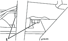
Identifying the Tie-Down Points
Pushing or Towing the Machine
In an emergency, you can move the machine by actuating the bypass valve in the variable displacement hydraulic pump, and then pushing or towing the machine.
Important: Do not push or tow the machine faster than 3 to 4.8 km/h (2 to 3 mph) because internal transmission damage may occur. The bypass valve must be open whenever you push or tow the machine.
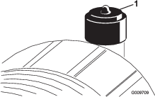
-
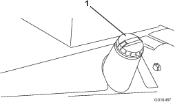
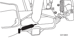
The bypass valve is located on top of variable displacement pump (Figure 34). Rotate the valve 90°, in either direction, to open and allow oil to bypass internally.
Note: You can now move the machine slowly without damaging the transmission.
-
Close the bypass valve before starting the engine.
Important: Running the engine with the bypass valve open will cause the transmission to overheat.
Note: Do not exceed 7 to 11 N∙m (5 to 8 ft-lb) torque to close the valve.
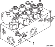
Hydraulic Solenoid Valve Functions
Use the list below to identify and describe the different functions of the solenoids in the hydraulic manifold. Each solenoid must be energized to allow function to occur.
| Solenoid | Function |
|---|---|
| MSV1 | Front reel circuit |
| MSV2 | Rear reel circuit |
| SV4 | Lift front wing cutting units |
| SV3 | Lift front center cutting unit |
| SV5 | Lift rear cutting units |
| SV1 | Pressurize raise/lower hydraulic circuit |
| SV2 | Direction: ON = Raise, OFF = Lower |
| SV 6 | Left rear wing cutting unit |
| SV 7 | Right rear wing cutting unit |
| SV8 | Load holding |
Maintenance
Note: Determine the left and right sides of the machine from the normal operating position.
Maintenance Safety
-
Before adjusting, cleaning, servicing, or leaving the machine, do the following:
-
Park the machine on a level surface.
-
Move the throttle switch to the low-idle position.
-
Disengage the cutting units.
-
Lower the cutting units.
-
Ensure that the traction is in neutral.
-
Engage the parking brake.
-
Shut off the engine and remove the key.
-
Wait for all moving parts to stop.
-
Allow machine components to cool before performing maintenance.
-
-
If possible, do not perform maintenance while the engine is running. Keep away from moving parts.
-
Use jack stands to support the machine or components when required.
-
Carefully release pressure from components with stored energy.
-
Keep all parts of the machine in good working condition and all hardware tightened.
-
Replace all worn or damaged decals.
-
To ensure safe, optimal performance of the machine, use only genuine Toro replacement parts. Replacement parts made by other manufacturers could be dangerous, and such use could void the product warranty.
Recommended Maintenance Schedule(s)
| Maintenance Service Interval | Maintenance Procedure |
|---|---|
| After the first 8 hours |
|
| After the first 50 hours |
|
| After the first 200 hours |
|
| Before each use or daily |
|
| Every 25 hours |
|
| Every 50 hours |
|
| Every 100 hours |
|
| Every 150 hours |
|
| Every 200 hours |
|
| Every 400 hours |
|
| Every 800 hours |
|
| Every 1,000 hours |
|
| Every 2,000 hours |
|
| Every 2 years |
|
Lubrication
Greasing the Bearings and Bushings
| Maintenance Service Interval | Maintenance Procedure |
|---|---|
| Every 50 hours |
|
Lubricate all grease fittings for the bearings and bushings with No. 2 lithium grease.
The grease fitting locations and quantities are as follows:
-
Cutting unit carrier frame and pivot (2) (Figure 35)
-
Rear axle tie rod (2) (Figure 36)
-
Steering cylinder ball joints (2) (Figure 36)
-
King pin bushings (2) (Figure 36) — The top fitting on the king pin should only be lubricated annually (2 pumps).
-
Front lift cylinders (3) (Figure 37 and Figure 38)
-
Rear lift cylinder pivot (2) (Figure 39)
-
Lift arm pivot (3) (Figure 40)
-
Rear axle pivot (Figure 41)
-
Rear lift arm pivots (2) (Figure 42)
-
Brake pedal shaft (1) (Figure 43)
Engine Maintenance
Engine Safety
-
Shut off the engine before checking the oil or adding oil to the crankcase.
-
Do not change the governor speed or overspeed the engine.
Servicing the Air Cleaner
| Maintenance Service Interval | Maintenance Procedure |
|---|---|
| Every 400 hours |
|
Check the air-cleaner body for damage which could cause an air leak. Replace it if it is damaged. Check the whole intake system for leaks, damage, or loose hose clamps.
Service the air-cleaner filter only when the service indicator (Figure 44) requires it. Changing the air filter before it is necessary only increases the chance of dirt entering the engine when you remove the filter.
Important: Ensure that the cover is seated correctly and seals with the air cleaner body.
-
Pull the latch outward and rotate the air cleaner cover counterclockwise (Figure 45).
-
Remove the cover from the air cleaner body. Before removing the filter, use low pressure air (275 kPa [40 psi], clean and dry) to help remove large accumulations of debris packed between outside of primary filter and the canister. Avoid using high pressure air which could force dirt through the filter into the intake tract.
This cleaning process prevents debris from migrating into the intake when the primary filter is removed.
-
Remove and replace the primary filter (Figure 46).
Cleaning of the used element is not recommended due to the possibility of damage to the filter media. Inspect the new filter for shipping damage, checking the sealing end of the filter and the body. Do not use a damaged element. Insert the new filter by applying pressure to the outer rim of the element to seat it in the canister. Do not apply pressure to the flexible center of the filter.
Important: Never attempt to clean the safety filter (Figure 47). Replace the safety filter with a new one after every three primary filter services.
-
Clean the dirt ejection port located in the removable cover. Remove the rubber outlet valve from the cover, clean the cavity and replace the outlet valve.
-
Install the cover orienting the rubber outlet valve in a downward position—between approximately 5:00 to 7:00 when viewed from the end.
-
Reset the indicator (Figure 44) if it shows red.
Checking the Engine Oil
| Maintenance Service Interval | Maintenance Procedure |
|---|---|
| Before each use or daily |
|
The engine is shipped with oil in the crankcase; however, check the oil level before and after the engine is first started.
Use high-quality engine oil that meets the following specifications:
-
API Classification Level Required: CH-4, CI-4 or higher.
-
Preferred oil: SAE 15W-40: above -18°C (0°F)
-
Alternate oil: SAE 10W-30 or 5W-30 (all temperatures)
Note: Toro Premium Engine oil is available from your distributor in either 15W-40 or 10W-30 viscosity. See the Parts Catalog for part numbers.
Note: The best time to check the engine oil is when the engine is cool before it has been started for the day. If it has already been run, allow the oil to drain back down to the sump for at least 10 minutes before checking. If the oil level is at or below the Add mark on the dipstick, add oil to bring the oil level to the Full mark. Do not overfill the engine. If the oil level is between the Full and Add marks, no oil addition is required.
-
Park the machine on a level surface, lower the cutting units, shut off the engine, engage the parking brake, and remove the key.
-
Release the hood latch and open the hood (Figure 48).
-
Remove the dipstick (Figure 49), wipe it clean, install the dipstick into the tube, and pull it out again.
Check the oil level on the dipstick; the oil level should be up to the Full mark on the dipstick.
-
If the oil is below the safe range, remove the fill cap (Figure 50) and add oil until the level reaches the Full mark.
Important: Do not overfill the engine.
-
Install the oil fill cap and dipstick.
-
Close the hood and secure it with the latches.
Servicing the Engine Oil and Filter
| Maintenance Service Interval | Maintenance Procedure |
|---|---|
| After the first 50 hours |
|
| Every 150 hours |
|
Capacity: 7.0 L (7.5 US qt) with filter
Change the oil and filter initially after the first 50 hours of operation, thereafter change oil and filter every 150 hours.
Adjusting the Throttle
-
Position the throttle lever forward so that it stops against the seat base slot.
-
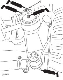
Loosen the throttle cable connector on the lever arm at the injection pump (Figure 53).
-
Hold the injection pump lever arm against the high idle stop and tighten the cable connector.
Note: When tightened, the cable connector must be free to swivel.
-
Torque the locknut, used to set the friction device on the throttle lever, to 4 to 6 N∙m (40 to 55 in-lb). The maximum force required to operate the throttle lever should be 80 N (20 lb).
Fuel System Maintenance
Draining the Fuel Tank
| Maintenance Service Interval | Maintenance Procedure |
|---|---|
| Every 2 years |
|
Park the machine on a level surface, lower the cutting units, engage the parking brake, shut off the engine, and remove the key.
Drain and clean the fuel tank every 2 years. Also, drain and clean the tank if the fuel system becomes contaminated or if the machine is to be stored for an extended period. Use clean fuel to flush out the tank.
Checking the Fuel Lines and Connections
| Maintenance Service Interval | Maintenance Procedure |
|---|---|
| Every 400 hours |
|
Check the fuel lines and connections for deterioration, damage, or loose connections.
Servicing the Water Separator
| Maintenance Service Interval | Maintenance Procedure |
|---|---|
| Before each use or daily |
|
| Every 400 hours |
|
-
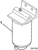
Park the machine on a level surface, lower the cutting units, engage the parking brake, shut off the engine, and remove the key.
-
Place a clean container under the fuel filter.
-
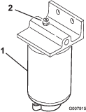
Loosen the drain plug on the bottom of the filter canister and open the vent on the top of the canister mount.
-
Clean the area where the filter canister mounts.
-
Remove the filter canister and clean the mounting surface.
-
Lubricate the gasket on the filter canister with clean oil.
-
Install the filter canister by hand until the gasket contacts the mounting surface, then rotate it an additional 1/2 turn.
-
Tighten the drain plug on the bottom of the filter canister and close the vent on the top of the canister mount.
Bleeding Air from the Injectors
Note: Perform this procedure only when the fuel system has been purged of air through normal priming procedures and the engine does not start; refer to Bleeding the Fuel System.
-
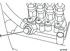
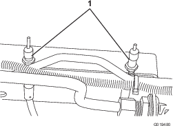
Loosen the pipe connection to the No. 1 nozzle and holder assembly.
-
Move the throttle to the FAST position.
-
Turn the key to the RUN position and watch for fuel to flow around the connector. Turn the key to the OFF position when you see a steady flow of fuel.
-
Tighten the pipe connector securely.
-
Repeat steps 1 through 4 on the remaining nozzles.
Note: You can remove the fan shroud from the machine to simplify cleaning.
-
Install the rear screen and secure the latches.
Important: Do not use water to clean the engine, as damage may occur.
Electrical System Maintenance
Electrical System Safety
-
Disconnect the battery before repairing the machine. Disconnect the negative terminal first and the positive last. Connect the positive terminal first and the negative last.
-
Charge the battery in an open, well-ventilated area, away from sparks and flames. Unplug the charger before connecting or disconnecting the battery. Wear protective clothing and use insulated tools.
Servicing the Battery
| Maintenance Service Interval | Maintenance Procedure |
|---|---|
| Every 25 hours |
|
The battery electrolyte level must be properly maintained and the top of the battery kept clean. If the machine is stored in a location where temperatures are extremely high, the battery will run down more rapidly than if the machine is stored in a location where temperatures are cool.
Danger
Battery electrolyte contains sulfuric acid which is a deadly poison and causes severe burns.
-
Do not drink electrolyte and avoid contact with skin, eyes or clothing. Wear safety glasses to shield your eyes and rubber gloves to protect your hands.
-
Fill the battery where clean water is always available for flushing the skin.
-
Charge the battery in a well-ventilated place so that the gasses produced while charging can dissipate.
-
Since the gases are explosive, keep open flames and electrical sparks away from the battery; do not smoke.
-
Nausea may result if the gases are inhaled.
-
Unplug the charger from the electrical outlet before connecting to or disconnecting the charger leads from the battery posts.
Maintain the cell level with distilled or demineralized water. Do not fill the cells above the bottom of the split ring inside each cell. Install the filler caps with the vents pointing to the rear (toward the fuel tank).
Keep the top of the battery clean by washing it periodically with a brush dipped in ammonia or bicarbonate of soda solution. Flush the top surface with water after cleaning. Do not remove the filler caps while cleaning.
The battery cables must be tight on the terminals to provide good electrical contact.
If corrosion occurs at the terminals, disconnect the cables, negative (–) cable first, and scrape the clamps and terminals separately. Connect the cables, positive (+) cable first, and coat the terminals with petroleum jelly.

Drive System Maintenance
Checking the Tire Pressure
| Maintenance Service Interval | Maintenance Procedure |
|---|---|
| Before each use or daily |
|
The tires are over-inflated for shipping. Therefore, release some of the air to reduce the pressure. Correct air pressure in the front and rear tires is 103 to 138 kPa (15 to 20 psi).
Danger
Low tire pressure decreases machine side hill stability. This could cause a rollover, which may result in personal injury or death.
Do not under-inflate the tires.
Checking the Torque of the Wheel Nuts and Bolts
| Maintenance Service Interval | Maintenance Procedure |
|---|---|
| After the first 8 hours |
|
| Every 200 hours |
|
Torque the wheel nuts and bolts to 115 to 135 N∙m (85 to 100 ft-lb).
Warning
Failure to maintain proper torque of the wheel nuts and bolts could result in personal injury.
Maintain the proper torque on the wheel nuts and bolts.
Checking the Planetary Gear Drive Oil
| Maintenance Service Interval | Maintenance Procedure |
|---|---|
| Every 400 hours |
|
Check the oil level every 400 hours of operation. Use high quality SAE 85W-140 gear oil as a replacement.
-
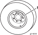
With the machine on a level surface, position the wheel so that 1 check plug (Figure 59) is at the 12 o'clock position and the other is at the 3 o'clock position.
-
Remove the plug at the 3 o’clock position (Figure 59). The oil level should be at the bottom of the check plug hole.
-
If the oil level is low, remove the plug at the 12 o’clock position and add oil until it begins to flow out of the hole at the 3 o’clock position.
-
Install both plugs.
-
Repeat steps 1 through 4 on the opposite planetary gear assembly.
Changing the Planetary Gear Drive Oil
| Maintenance Service Interval | Maintenance Procedure |
|---|---|
| After the first 200 hours |
|
| Every 800 hours |
|
Change the oil initially after 200 hours operation. Thereafter, change the oil every 800 hours. Use high quality SAE 85W-140 gear oil as replacement.
-
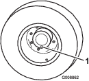
With the machine on level surface, position a wheel so that one of the check/drain plugs is at the lowest (6 o’clock) position (Figure 60).
-
Place a drain pan under the planetary hub, remove the plug, and allow the oil to drain.
-
Place a drain pan under the brake housing, remove the drain plug, and allow the oil to drain (Figure 61).
-
When all of the oil has drained from both locations, install the plug in the brake housing.
-
Rotate the wheel until the open plug hole in the planetary is at the 12 o'clock position.
-
Install the plug.
-
Repeat the procedure on the opposite planetary/brake assembly.
Checking the Rear Axle Lubricant
| Maintenance Service Interval | Maintenance Procedure |
|---|---|
| Every 400 hours |
|
The rear axle is shipped from the factory filled with SAE 85W-140 gear oil. Check the level before first starting the engine and every 400 hours thereafter. Capacity is 2.3 L (80 fl oz). Visually inspect for leaks daily.
-
Park the machine on a level surface, lower the cutting units, shut off the engine, engage the parking brake, and remove the key.
-
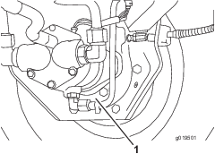
Remove a check plug (Figure 62) from 1 end of axle and make sure lubricant is up to the bottom of the hole. If the level is low, remove the fill plug (Figure 62) and add enough oil to bring the level up to the bottom of the check plug holes.
Changing the Rear Axle Lubricant
| Maintenance Service Interval | Maintenance Procedure |
|---|---|
| After the first 200 hours |
|
| Every 800 hours |
|
Change the oil initially after the first 200 hours of operation and every 800 hours of operation thereafter.
-
Park the machine on a level surface, lower the cutting units, shut off the engine, engage the parking brake, and remove the key.
-
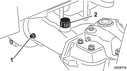
Clean the area around the 3 drain plugs: 1 on each end and 1 in the center (Figure 63).
-
Remove the 3 oil level check plugs and the main axle vent cap to ease in draining of the oil.
-
Remove the drain plugs and allow the oil to drain into the pans.
-
Install the plugs.
-
Remove a check plug and fill the axle with approximately 2.3 L (80 fl oz) of 85W-140 gear oil or until oil is up to the bottom of the hole.
-
Install the check plug.
Checking the Rear Wheel Toe-In
| Maintenance Service Interval | Maintenance Procedure |
|---|---|
| Every 800 hours |
|
After every 800 operating hours or annually, check the rear wheel toe-in.
-
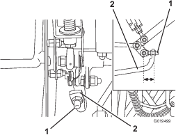
Measure the center-to-center distance (at axle height) at the front and rear of the steering tires. The front measurement must be 3 mm (1/8 inch) less than the rear measurement.
-
To adjust the distance, remove the cotter pin and nut from either tie rod ball joint. Remove the tie rod ball joint from the axle case support (Figure 64).
-
Loosen the clamps at both ends of the tie rods (Figure 64).
-
Rotate the detached ball joint inward or outward 1 complete revolution. Tighten the clamp at the loose end of the tie rod.
-
Rotate the entire tie rod assembly the same direction (inward or outward) 1 complete revolution. Tighten the clamp at the connected end of the tie rod.
-
Install the ball joint in the axle case support and tighten the nut finger tight. Measure the toe-in.
-
Repeat the procedure if necessary.
-
Tighten the nut and install a new cotter pin when the adjustment is correct.
Adjusting the Traction Drive for Neutral
The machine must not creep when you release the traction pedal. If it does creep, an adjustment is required.
-
Park the machine on a level surface, lower the cutting units, shut off the engine, press only the right brake pedal and engage the parking brake.
-
Jack up left side of machine until the front tire and the rear tire are off the shop floor. Support the machine with jack stands to prevent it from falling accidentally.
-
Start the engine and allow it to run at low idle.
-
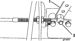
Adjust the jam nuts on the pump rod end to move the pump control tube forward to eliminate forward creep or rearward to eliminate rearward creep (Figure 65).
-
After wheel rotation ceases, tighten the jam nuts to secure the adjustment.
-
Shut off the engine and release the right brake. Remove the jack stands and lower the machine to the shop floor. Test drive the machine to ensure that it does not creep.
Cooling System Maintenance
Cooling System Safety
-
Swallowing engine coolant can cause poisoning; keep out of reach from children and pets.
-
Discharge of hot, pressurized coolant or touching a hot radiator and surrounding parts can cause severe burns.
-
Always allow the engine to cool at least 15 minutes before removing the radiator cap.
-
Use a rag when opening the radiator cap, and open the cap slowly to allow steam to escape.
-
Removing Debris
| Maintenance Service Interval | Maintenance Procedure |
|---|---|
| Before each use or daily |
|
Remove debris from the rear screen, oil cooler, and radiator daily (more frequently in dirty conditions).
Important: Never spray water onto a hot engine as damage to the engine may occur.
-
Park the machine on a level surface, lower the cutting units, shut off the engine, engage the parking brake, and remove the key.
-
Open the hood.
-
Clean the engine area thoroughly of all debris.
-
Close the hood.
-
Unlatch and remove the rear screen (Figure 66).
-
Clean the screen thoroughly.
-
Unscrew the knobs and pivot the oil cooler rearward (Figure 67).
-
Clean both sides of the oil cooler and radiator area thoroughly with compressed air. Do not use water.
-
Open the hood and blow the debris out toward the back of the machine.
-
Pivot the oil cooler back into position and tighten the knobs.
Checking the Cooling System
| Maintenance Service Interval | Maintenance Procedure |
|---|---|
| Before each use or daily |
|
The capacity of the cooling system is 9.4 L (10 US qt).
-
Clean the debris off the screen, the oil cooler, and the front of the radiator daily (more often if conditions are extremely dusty and dirty); refer to Removing Debris.
The cooling system is filled with a 50/50 solution of water and permanent ethylene glycol antifreeze. Check the level of the coolant in the radiator and the expansion tank at the beginning of each day before starting the engine.
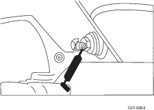
Carefully remove the radiator cap and the expansion tank cap (Figure 68).
-
Check the level of coolant in the radiator and in the expansion tank (Figure 68).
The radiator should be filled to the top of the filler neck and the expansion tank filled to the Full mark.
-
Fill the expansion tank to the Full mark and the radiator to the top of the filler neck. Do not overfill the expansion tank.
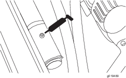
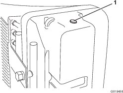
Note: If air is trapped in the system, remove the vent plug (Figure 69) from the top of the radiator side tank to allow trapped air to escape. Install the vent plug using PTFE thread sealant.
-
Install the radiator cap and the expansion tank cap.
-
Close the hood and secure the latches.
Maintaining the Cooling System
| Maintenance Service Interval | Maintenance Procedure |
|---|---|
| Every 100 hours |
|
| Every 2 years |
|
Capacity: 9.4 L (10 US qt)
Protect the cooling system with a 50/50 solution of water and permanent ethylene glycol anti-freeze. Do not use only water in the cooling system.
-
After every 100 operating hours, inspect and tighten the hose connections. Replace any deteriorated hoses.
-
After every 2 years, drain and flush the cooling system. Add anti-freeze; refer to Checking the Cooling System.
Brake Maintenance
Adjusting the Service Brakes
Adjust the service brakes when there is more than 2.5 cm (1 inch) of free travel of the brake pedal, or when the brakes do not work effectively. Free travel is the distance the brake pedal moves before braking resistance is felt.
-
Disengage the locking pin from the brake pedals so that both pedals work independently of each other.
-
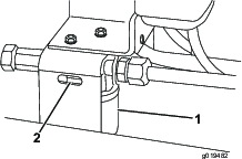
To reduce the amount of free travel of the brake pedals, tighten the brakes by loosening the front nut on the threaded end of the brake cable (Figure 70). Then tighten rear nut to move cable backward until brake pedals have 1.2 to 2.5 cm (1/2 to 1 inch) of free travel. Tighten the front nuts after the brakes are adjusted correctly.
Belt Maintenance
Checking the Alternator Belt
| Maintenance Service Interval | Maintenance Procedure |
|---|---|
| Every 100 hours |
|
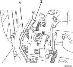
Check condition and tension of alternator belt after every 100 hours of operation (Figure 71). Replace belt as required. Check the tension as follows:
-
Open the hood.
-
Check the tension by pressing the belt midway between the alternator and the crankshaft pulleys with 97 N (22 lb) of force. The belt should deflect 1.1 cm (7/16 inch). If the deflection is incorrect, proceed to step 3. If it is correct, continue operation.
-
Loosen the bolt securing the brace to the engine and the bolt securing the alternator to the brace.
-
Insert a pry bar between the alternator and the engine and pry out on the alternator.
-
When proper tension is achieved, tighten the alternator and brace bolts to secure the adjustment.
-
Tighten the locknut to secure the adjustment.
Hydraulic System Maintenance
Hydraulic System Safety
-
Seek immediate medical attention if fluid is injected into skin. Injected fluid must be surgically removed within a few hours by a doctor.
-
Ensure that all hydraulic-fluid hoses and lines are in good condition and all hydraulic connections and fittings are tight before applying pressure to the hydraulic system.
-
Keep your body and hands away from pinhole leaks or nozzles that eject high-pressure hydraulic fluid.
-
Use cardboard or paper to find hydraulic leaks.
-
Safely relieve all pressure in the hydraulic system before performing any work on the hydraulic system.
Checking the Hydraulic Fluid
| Maintenance Service Interval | Maintenance Procedure |
|---|---|
| Before each use or daily |
|
-
Park the machine on a level surface, lower the cutting units, shut off the engine, engage the parking brake, and remove the key.
-
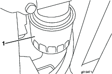
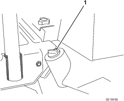
Clean the area around the filler neck and cap of the hydraulic tank (Figure 72). Remove the cap from the filler neck.
-
Remove the dipstick from the filler neck and wipe it with a clean rag. Insert the dipstick into the filler neck, then remove it and check the level of the fluid. The fluid level should be within 6 mm (1/4 inch) of the mark on the dipstick.
-
If the level is low, add the appropriate fluid to raise the level to the full mark.
-
Install the dipstick and cap onto the filler neck.
Hydraulic Fluid Specifications
The reservoir is filled at the factory with high-quality hydraulic fluid. Check the level of the hydraulic fluid before you first start the engine and daily thereafter; refer to Checking the Hydraulic Fluid.
Recommended hydraulic fluid: Toro PX Extended Life Hydraulic Fluid; available in 19 L (5 US gallon) pails or 208 L (55 US gallon) drums.
Note: A machine using the recommended replacement fluid requires less frequent fluid and filter changes.
Alternative hydraulic fluids: If Toro PX Extended Life Hydraulic Fluid is not available, you may use another conventional, petroleum-based hydraulic fluid having specifications that fall within the listed range for all the following material properties and that it meets industry standards. Do not use synthetic fluid. Consult with your lubricant distributor to identify a satisfactory product.
Note: Toro does not assume responsibility for damage caused by improper substitutions, so use products only from reputable manufacturers who will stand behind their recommendation.
| Material Properties: | ||
| Viscosity, ASTM D445 | cSt @ 40°C (104°F) 44 to 48 | |
| Viscosity Index ASTM D2270 | 140 or higher | |
| Pour Point, ASTM D97 | -37°C to -45°C (-34°F to -49°F) | |
| Industry Specifications: | Eaton Vickers 694 (I-286-S, M-2950-S/35VQ25 or M-2952-S) | |
Note: Many hydraulic fluids are almost colorless, making it difficult to spot leaks. A red dye additive for the hydraulic fluid is available in 20 ml (0.67 fl oz) bottles. A bottle is sufficient for 15 to 22 L (4 to 6 US gallons) of hydraulic fluid. Order Part No. 44-2500 from your authorized Toro distributor.
Important: Toro Premium Synthetic Biodegradable Hydraulic Fluid is the only synthetic biodegradable fluid approved by Toro. This fluid is compatible with the elastomers used in Toro hydraulic systems and is suitable for a wide-range of temperature conditions. This fluid is compatible with conventional mineral oils, but for maximum biodegradability and performance, the hydraulic system should be thoroughly flushed of conventional fluid. The oil is available in 19 L (5 US gallons) pails or 208 L (55 US gallons) from your authorized Toro distributor.
Hydraulic Fluid Capacity
32 L (8.5 US gallons); refer to Hydraulic Fluid Specifications
Changing the Hydraulic Fluid
| Maintenance Service Interval | Maintenance Procedure |
|---|---|
| Every 800 hours |
|
| Every 2,000 hours |
|
If the fluid becomes contaminated, contact a Toro distributor to flush the hydraulic system. Contaminated hydraulic fluid looks milky or black when compared to clean fluid.
-
Park the machine on a level surface, lower the cutting units, shut off the engine, engage the parking brake, and remove the key.
-
Open the hood.
-
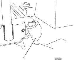
Remove the drain plug from the bottom of the reservoir (Figure 73) and let the hydraulic fluid flow into a drain pan.
-
Install and tighten the plug when the hydraulic fluid stops draining.
-
Fill the reservoir with hydraulic fluid; refer to Hydraulic Fluid Specifications and Hydraulic Fluid Capacity.
Important: Use only the hydraulic fluids specified. Other fluids could cause system damage.
-
Install the reservoir cap. Start the engine and use all the hydraulic controls to distribute the hydraulic fluid throughout the system.
-
Check for leaks.
-
Shut off the engine.
-
Check the level of the fluid and add enough to raise the level to the full mark on the dipstick.
Important: Do not overfill the reservoir.
Replacing the Hydraulic Filter
| Maintenance Service Interval | Maintenance Procedure |
|---|---|
| Every 800 hours |
|
| Every 1,000 hours |
|
The hydraulic system filter head is equipped with a service interval indicator. With the engine running, view the indicator—it should be in the green zone. When the indicator is in the red zone, change the filter element.
Use the Toro replacement filter (Part No. 94-2621).
Important: Use of any other filter may void the warranty on some components.
-
Park the machine on a level surface, lower the cutting units, shut off the engine, engage the parking brake, and remove the key.
-
Clean the area around the filter mounting area. Place a drain pan under the filter and remove the filter (Figure 74).
-
Lubricate the new filter gasket and fill the filter with hydraulic fluid.
-
Ensure that the filter mounting area is clean. Screw the filter on until the gasket contacts the mounting plate. Then, tighten the filter 1/2 turn.
-
Start the engine and let it run for about 2 minutes to purge air from the system.
-
Shut off the engine and remove the key, and check for leaks.
Checking the Hydraulic Lines and Hoses
| Maintenance Service Interval | Maintenance Procedure |
|---|---|
| Before each use or daily |
|
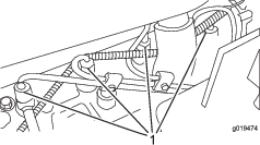
Check the hydraulic lines and hoses for leaks, kinked lines, loose mounting supports, wear, loose fittings, weather deterioration, and chemical deterioration. Make all necessary repairs before operating.
Using the Hydraulic System Test Ports
The test ports are used to test pressure in the hydraulic circuits. Contact your authorized Toro distributor for assistance.
-
Test Port A (Figure 75) is used to assist in troubleshooting the hydraulic circuit for the lift cylinders.
-
Test Port B (Figure 76) is used to assist in troubleshooting the hydraulic circuit for the front cutting units.
-
Test Port C (Figure 76) is used to assist in troubleshooting the hydraulic circuit for the rear cutting units.
-
Test Port D is located on the bottom of the hydrostatic transmission (Figure 77) and is used to measure the charge pressure of the transmission.
-
Test Port E is used to measure traction forward pressure (Figure 77).
-
Test Port F is used to measure traction reverse pressure (Figure 77).
-
Test Port G is used to measure steering circuit pressure (Figure 77).
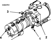
Cutting Unit System Maintenance
Blade Safety
-
A worn or damaged blade or bedknife can break, and a piece could be thrown toward you or bystanders, resulting in serious personal injury or death.
-
Inspect the cutting units periodically for excessive wear or damage.
-
Use care when checking the cutting units. Wrap the blades or wear gloves, and use caution when servicing the reels and bedknives. Only replace or sharpen the reels and bedknives; never straighten or weld them.
-
On machines with multiple cutting units, take care when rotating a reel; it can cause the reels in the other cutting units to rotate.
Checking the Reel-to-Bedknife Contact
| Maintenance Service Interval | Maintenance Procedure |
|---|---|
| Before each use or daily |
|
Check the reel-to-bedknife contact even if the quality of cut had been acceptable previously. There must be light contact across the full length of the reel and bedknife; refer to Adjusting Reel to Bedknife in the cutting unit operator’s manual.
Backlapping the Cutting Units
Note: When backlapping, the front units all operate together, and the rear units operate together.
-
Park the machine on a level surface, lower the cutting units, shut off the engine, engage the parking brake, and move the Enable/Disable switch to disable position.
-
Unlock and raise the seat to expose the controls.
-
Locate the reel speed selector knobs and backlap knobs (Figure 78). Rotate the desired backlap knob(s) to the backlap position and the desired reel speed selector knob(s) to position 1.
Note: Backlapping speed may be increased by moving the reel speed selector knob toward 13. Each position increases the speed approximately 100 rpm. After changing the selector, wait 30 seconds for the system to stabilize at the new speed.
-
Make initial reel to bedknife adjustments appropriate for backlapping on all cutting units which are to be backlapped.
-
Start the engine and run it at idle speed.
-
Select either front, rear, or both backlap knobs to determine which reels will be backlapped.
-
Move the Enable/Disable switch to the Enable position. Move the Lower Mow/Lift control forward to start the backlapping operation on the designated reels.
-
Apply lapping compound with a long-handled brush (Toro Part No. 29-9100). Never use a short-handled brush.
-
If the reels stall or become erratic while backlapping, stop backlapping by moving the Lower Mow/Lift control lever rearward. Once the reels have stopped, move the desired reel speed selector knob(s) one position closer to 13. Resume backlapping by moving the Lower Mow/Lift control lever forward.
-
To make an adjustment to the cutting units while backlapping, stop the cutting units by moving the Lower Mow/Raise lever rearward; move the Enable/Disable switch to Disable and shut off the engine. After adjustments have been completed, repeat steps 5 through 9.
-
When the cutting unit is adequately sharpened, a burr will form on the front edge of the knife. Using a file, carefully remove the burr without dulling the cutting edge.
-
Repeat the procedure for all cutting units to be backlapped.
When you are finished with the backlap operation, return the backlap knobs to the forward flow position, lower the seat, and wash all lapping compound off the cutting units. Adjust the reel-to-bedknife contact as needed.
Note: If you do not return the backlap knobs to the forward flow position after backlapping, the cutting units will not raise or function properly.
Adjusting the Cutting Unit Lowering Rate
The machine is set up at the factory for most fairway mowing applications.
The following adjustments are available for fine-tuning of the machine to the application:
The cutting unit lift circuits are equipped with adjustable valves to ensure that the cutting units lower at the desired rate. Adjust them as follows:
-
Run the machine until it warms up to operating temperature.
-
Locate the valves, on the lift manifold, for adjusting the desired cutting unit(s); refer to the chart and Figure 79.
Valve Cutting Unit Affected FC1 #1 (front center) FC4 #4 and #5 (front wings) FC5 #2 and #3 (rear) FC6 #6 (rear left) FC7 #7 (rear right) 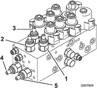
-
Loosen the locking nuts on the valves.
-
Using a hex key, rotate the appropriate valve clockwise to slow down the drop rate of the cutting units.
-
Verify the lift rate adjustment by raising and lowering cutting units several times. Adjust it as required.
-
Tighten the locking nut to secure the adjustment.
Adjusting the Lifted Height of the Outer Front Cutting Units (Enable Position)
You can increase the turnaround height of the front outer cutting units (#4 and #5) and rear cutting units (#6 and #7) to provide additional ground clearance on contoured fairways.
Note: The RM CONFIG time delay should not be changed from the original setting of 0 when using this method to adjust the turnaround height.
To increase/adjust the turn around height of the cutting units proceed as follows:
-
Park the machine on a level surface, lower the cutting units, shut off the engine, engage the parking brake, and remove the key.
-
Loosen the carriage bolt nut securing the lift arm switch bracket to the #4, 6, or 7 lift arms (Figure 80).
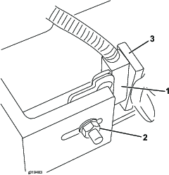
-
Move the lift switch bracket up in the slot to the desired position.
-
Set the distance between the lift arm switch and the flag on the lift arm to approximately 1.6 mm (0.062 inch).
-
Tighten carriage bolt nut.
Adjusting the Travel of the Front 3 Cutting Units
Additional downward travel of the front 3 cutting units may be desirable in highly contoured locations. If any of the front 3 cutting units lift off the ground when cresting a hill, you can lower the front carrier frame by removing the mounting bolts and positioning frame in the bottom set of holes in the main frame (Figure 81). Contact your authorized Toro distributor for assistance.
Note: Moving the carrier frame down decreases the amount of clearance between the cutting units and the ground in turnaround and transport positions and may require adjusting the lift chain length on the cutting unit.
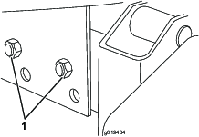
Storage
Storage Safety
-
Shut off the engine, remove the key, wait for all movement to stop before you leave the operator’s position. Allow the machine to cool before adjusting, servicing, cleaning, or storing it.
-
Do not store the machine or fuel container where there is an open flame, spark, or pilot light, such as on a water heater or on other appliances.
Preparing the Traction Unit
-
Park the machine on a level surface, lower the cutting units, engage the parking brake, shut off the engine, and remove the key.
-
Thoroughly clean the traction unit, cutting units, and the engine.
-
Check the tire pressure; refer to Checking the Tire Pressure.
-
Check all fasteners for looseness; tighten them as necessary.
-
Grease or oil all grease fittings and pivot points. Wipe up any excess lubricant.
-
Lightly sand and use touch-up paint on painted areas that are scratched, chipped, or rusted. Repair any dents in the metal body.
-
Service the battery and cables as follows; refer to Electrical System SafetyID000-448-328:
-
Remove the battery terminals from the battery posts.
-
Clean the battery, terminals, and posts with a wire brush and baking-soda solution.
-
Coat the cable terminals and battery posts with Grafo 112X skin-over grease (Toro Part No. 505-47) or petroleum jelly to prevent corrosion.
-
Slowly charge the battery every 60 days for 24 hours to prevent lead sulfation of the battery.
-
Preparing the Engine
-
Drain the engine oil from the oil pan and install the drain plug.
-
Remove and discard the oil filter. Install a new oil filter.
-
Fill the engine with specified motor oil.
-
Start the engine and run it at idle speed for approximately 2 minutes.
-
Shut off the engine and remove the key.
-
Flush the fuel tank with fresh, clean fuel.
-
Secure all of the fuel-system fittings.
-
Thoroughly clean and service the air-cleaner assembly.
-
Seal the air-cleaner inlet and the exhaust outlet with weatherproof tape.
-
Check the antifreeze protection and add a 50/50 solution of water and ethylene glycol antifreeze as needed for the expected minimum temperature in your area.