Introduction

Read this information carefully to learn how to operate and maintain your product properly and to avoid injury and product damage. You are responsible for operating the product properly and safely.

Visit www.Toro.com for more information, including safety tips, training materials, accessory information, help finding a dealer, or to register your product.

Whenever you need service, genuine Toro parts, or additional information, contact an Authorized Service Dealer or Toro Customer Service and have the model and serial numbers of your product ready. Figure 1 identifies the location of the model and serial numbers on the product. Write the numbers in the space provided.

g003440

This manual identifies potential hazards and has safety messages identified by the safety-alert symbol (Figure 2), which signals a hazard that may cause serious injury or death if you do not follow the recommended precautions.

g000502

This manual uses 2 words to highlight information. Important calls attention to special mechanical information and Note emphasizes general information worthy of special attention.

Safety

Safety and Instructional Decals

Graphic

Safety decals and instructions are easily visible to the operator and are located near any area of potential danger. Replace any decal that is damaged or missing.

decal106-5517

Setup

Assembling the Lift Arm/Attachment Adapter to the Rear Broom

Parts needed for this procedure:

Rear broom assembly
Drawbar assembly1
Bolt (3/8 x 1 inch)1
Bolt (1/2 x 1-3/4 inches)1
Flange nut (1/2 inch)1
Hex nut (1/2 inch)1
Flange nut (3/8 inch)1
Lift arm/attachment adapter assembly1
Pivot bar1
Large cotter3
Bolt (3/8 x 1-1/4 inches)1
Locknut (3/8 inch)1
Thick washer (1/2 inch)3
Locknut (7/16 inch)1
Bolt (1/2 x 5-1/2 inches)
Locknut (1/2 inch)1
Spacers2
Clevis pin (1/2 x 5 inches)2
Thick washer (1/2 inch)2
Long cotter pin1
  1. Loosely mount the drawbar assembly to the front hole in the rear broom assembly with a large bolt (1/2 x 1-3/4 inches), flange nut (1/2 inch), hex nut (1/2 inch), and a small bolt (3/8 x 1 inch) and flange nut (3/8 inch) as shown in Figure 3.

    g274944
  2. Align the lift arm with the bracket on the attachment adapter (Figure 4) and connect them using the pivot bar as illustrated in Figure 5.

    Note: When moving the attachment adapter, use the handle provided on the back of the adapter (Figure 4).

    g266520
    g266521
  3. Secure the pivot bar (Figure 5) with 3 cotter pins, a bolt (3/8 x 1-1/4 inches), and a locknut (3/8 inch).

  4. Connect the drawbar assembly to the attachment adapter with a bolt (1/2 x 5-1/2 inches), spacers, locknut (1/2 inch), clevis pin (1/2 x 5 inches), 2 thick washers (1/2 inch), and a cotter pin.

    Note: When moving the attachment adapter, use the handle provided on the back of the adapter.

    g275098

Mounting the Rear Broom to the Traction Unit

Parts needed for this procedure:

Bolt (3/8 x 2-1/2 inches) 2
Washer (3/8 x 7/8 inch) 4
Spacer 2
Locknut (3/8 inch) 2
  1. Remove any attachment from the rear of the machine.

  2. Lower the traction unit adapter and back the traction unit into position in front of the attachment adapter.

    Note: Make sure the locking lever is pivoted to the left (unlocked position) as viewed from the rear of the machine.

  3. Slide the attachment adapter onto the traction adapter.

    Important: The long arm of the lift arm assembly must be under the traction unit rear frame assembly (Figure 7).

    Caution

    You could pinch your fingers between the attachment and traction unit adapters.

    Always lift and move the attachment using the handle on the back of the attachment adapter (Figure 7).

  4. Pivot the locking lever to the right to lock the adapters together.

  5. Secure the top link of each chain to the outside of the lift arm (Figure 7) using a bolt (3/8 x 2-1/2 inches), 2 washers (3/8 x 7/8 inch), a spacer, and a locknut (3/8 inch).

    g220791

    Note: For proper operation of the rake, the chains must be slack when the rake is in the lowered (operating) position.

    Note: Make sure that all the finishing rakes overlap properly, laying flat with none of the chains tangled or twisted.

Removing the Rear Broom from the Traction Unit

  1. Pivot the locking lever to the left (as viewed from the rear of the machine) to unlock the adapters (Figure 8).

    g005342
  2. Lower the traction unit adapter.

  3. Grasp the adapter handle and lift the attachment adapter while pivoting it back onto the attachment (Figure 8).

    Note: If the attachment adapter becomes stuck to the traction unit adapter, insert a pry bar into the pry slot to disengage the parts (Figure 9).

    g003783

Adjusting the Link Assembly

  1. With the rake mounted and secured on the traction unit, raise the attachment.

  2. Measure the gap between the heavy washer and the shoulder of the lift yoke on the attachment adapter as shown in Figure 10.

    Note: The link is adjusted correctly if you measure a gap—1.5 to 2 mm (0.060 to 0.080 inch) between the heavy washer and the lift-yoke shoulder (Figure 10).

    g220790
  3. If the gap is not correct, loosen the jam nut and tighten or loosen the adjustment nut on the link assembly as needed to change the gap (Figure 10).

Product Overview

g003463

Operation

Adjusting the Rear Broom Angle

You can change the angle of the broom to increase or decrease its aggressiveness in the sand. Mount the broom pivot to the bottom holes in the attachment adapter brackets for less aggressive raking or the top holes for more aggressive raking (Figure 12).

g003416

Adjusting the Broom Head Angle

You can change the angle of the broom heads in respect to the ground.

  1. Loosen the nut and bolt securing the broom head pivot brackets (Figure 14).

  2. Remove the 2 adjustment bolts and nuts from the broom head pivot brackets (Figure 14).

  3. Install and secure the adjustment bolts and nuts into the desired location as shown in Figure 14, Figure 15, and Figure 16.

    g003418
    g003419
    g003420

Setting the Transport Position

Complete the following procedure to increase the height of the broom when transporting:

  1. Lower the broom and lift assembly as far down as possible.

  2. Disconnect the chains from the lift arms and reconnect them higher.

    Note: To ensure the proper operation of the broom, the chains must be returned to the original slack position before operating.

Attachments/Accessories

A selection of Toro approved attachments and accessories is available for use with the machine to enhance and expand its capabilities. Contact your Authorized Service Dealer or authorized Toro distributor or go to www.Toro.com for a list of all approved attachments and accessories.

To ensure optimum performance and continued safety certification of the machine, use only genuine Toro replacement parts and accessories. Replacement parts and accessories made by other manufacturers could be dangerous, and such use could void the product warranty.

In particular, you can obtain the following for this attachment:

  • Wing weights, for use in heavy, wet conditions or on embankments

  • Stiff bristled brooms

Important: When installing new brooms, ensure that you install them with the shorter bristles towards the front of the attachment.

Operating Tips

Read this section before raking a trap. Many conditions affect the which adjustments are necessary; the texture and depth of the sand, moisture content, weeds, the amount of compaction can all vary from course to course and trap to trap. Make the adjustments on the broom for optimum results in your particular area.

Raking Speed

Practice raking in a large and level trap. Practice starting and stopping, turning, raising and lowering the broom, and entering and leaving the trap. Practice operating at a moderate engine speed and a slow ground speed. If your ground speed is too slow, a ridge may form in the sand from the gap between the brushes. If your ground speed is too fast, the brushes may bounce leaving an undesirable appearance.

Raking Information

If the sand is deep enough, you can rake up to the edge of the trap in level areas. If the sand feathers out to the turf, stay far enough away from the edge to avoid disturbing the underlying soil. Do not rake too close to a short steep bank; this causes the sand to flow down into the bottom of the trap. Some touch up with a hand rake may be necessary on steep banks, small pockets, etc. When operating the broom in wet, heavy sand and the desired appearance is not obtained, optional stiffer bristle brushes may be obtained. On steeper grades, when additional ground contact is required, an optional wing weight kit is available.

Raking Pattern

The recommended pattern for raking a trap is shown in Figure 16. This pattern avoids unnecessary overlap, holds compaction to a minimum and leaves a neat, attractive pattern on the sand. Enter the trap straight into the long dimension, where the bank is the least severe. Drive through the center of the trap almost to the end, turn to either direction as sharp as you can, and rake back next to the first pass. Spiral outward as shown in the drawing, and leave the trap at a right angle in a level area. Leave steep, short banks and small pockets for touch-up with a hand rake.

g003409

Entering and Leaving the Trap

When entering the trap, do not lower the broom until the broom is actually over the sand. This will avoid cutting the turf or dragging grass clippings or other debris into the trap. Lower the broom while the machine is moving. When leaving the trap, start raising the broom when the front wheel leaves the trap. As the machine moves out, the broom will be lifting and will not drag sand out onto the grass. Practice this to get the correct timing.

Maintenance

Inspecting and Cleaning the Broom and Traction Unit

Maintenance Service IntervalMaintenance Procedure
After each use
  • Clean the machine
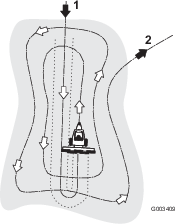
  • Clean the machine thoroughly after use. Because sand is extremely abrasive, the sand should be flushed off after each use. If the machine is cleaned frequently, (before the sand has a chance to cake), it can be cleaned with a stream of water from a hose with the nozzle removed. A high pressure stream could drive the sand into wear areas where it could act as a grinding compound.

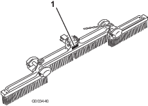
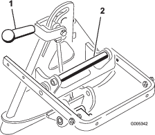
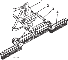
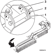
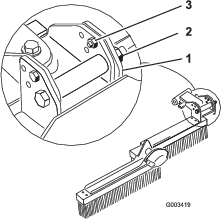
    Important: After using the broom do not allow it to rest on the bristles. The weight of the attachment will permanently distort the shape of the bristles and ruin the brooms. Always tip the broom up onto the attachment adapter after detaching the rear broom from the traction unit.

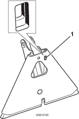
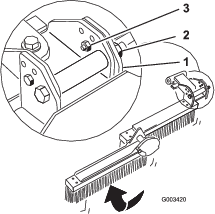
    Greasing the Attachment Adapter

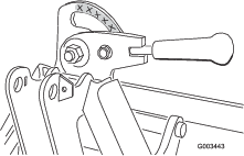
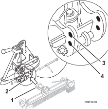
    If the locking lever on the attachment adapter does not pivot freely and easily, apply a light coat of grease to the area shown in Figure 17.

    g003443