Introduction

This cutting unit is designed for cutting turf on greens and small fairways of golf courses. Using this product for purposes other than its intended use could prove dangerous to you and bystanders.

Read this information carefully to learn how to operate and maintain your product properly and to avoid injury and product damage. You are responsible for operating the product properly and safely.

Visit www.Toro.com for product safety and operation training materials, accessory information, help finding a dealer, or to register your product.

Whenever you need service, genuine Toro parts, or additional information, contact an Authorized Service Dealer or Toro Customer Service and have the model and serial numbers of your product ready. Figure 1 identifies the location of the model and serial numbers on the product. Write the numbers in the space provided.

Important: With your mobile device, you can scan the QR code on the serial number plate (if equipped) to access warranty, parts, and other product information.

g279643

This manual identifies potential hazards and has safety messages identified by the safety-alert symbol (Figure 2), which signals a hazard that may cause serious injury or death if you do not follow the recommended precautions.

g000502

This manual uses 2 words to highlight information. Important calls attention to special mechanical information and Note emphasizes general information worthy of special attention.

This product complies with all relevant European directives. For details, please see the Declaration of Incorporation (DOI) at the back of this publication.

Safety

This machine has been designed in accordance with EN ISO 5395 and ANSI B71.4–2017.

General Safety

This product is capable of amputating hands and feet. Always follow all safety instructions to avoid serious personal injury.

  • Read and understand the contents of this Operator’s Manual before starting the machine.

  • Use your full attention while operating the machine. Do not engage in any activity that causes distractions; otherwise, injury or property damage may occur.

  • Do not put your hands or feet near moving components of the machine.

  • Do not operate the machine without all guards and other safety protective devices in place and functioning properly on the machine.

  • Keep clear of any discharge opening.

  • Keep bystanders and children out of the operating area. Never allow children to operate the machine.

  • Before you leave the operator’s position, do the following:

    • Park the machine on a level surface.

    • Lower the cutting unit(s).

    • Disengage the drives.

    • Engage the parking brake (if equipped).

    • Shut off the engine and remove the key (if equipped).

    • Wait for all movement to stop.

Improperly using or maintaining this machine can result in injury. To reduce the potential for injury, comply with these safety instructions and always pay attention to the safety-alert symbolGraphic
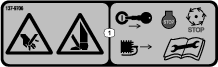
, which means Caution, Warning, or Danger—personal safety instruction. Failure to comply with these instructions may result in personal injury or death.

Cutting Unit Safety

  • The cutting unit is only a complete machine when installed on a traction unit. Read the traction unit Operator’s Manual carefully for complete instructions on the safe use of the machine.

  • Stop the machine, remove the key (if equipped), and wait for all movement to stop before inspecting the attachment after striking an object or if there is an abnormal vibration in the machine. Make all necessary repairs before resuming operation.

  • Keep all parts in good working condition and all hardware tightened. Replace all worn or damaged decals.

  • Use only accessories, attachments, and replacement parts approved by Toro.

Blade Safety

A worn or damaged blade can break, and a piece of the blade could be thrown toward you or bystanders, resulting in serious personal injury or death.

  • Inspect the blade periodically for wear or damage.

  • Use care when checking the blades. Wrap the blades or wear gloves, and use caution when servicing the blades. Only replace or sharpen the blades; never straighten or weld them.

  • On multi-bladed machines, take care as rotating 1 blade can cause other blades to rotate.

Safety and Instructional Decals

Graphic

Safety decals and instructions are easily visible to the operator and are located near any area of potential danger. Replace any decal that is damaged or missing.

decal137-9706

Setup

Installing the Roller

The cutting unit is shipped without a front roller. Obtain a roller from your authorized Toro distributor and install it on the cutting unit, as follows:

  1. Remove the plow bolt and flange locknut securing one of the height-of-cut arms to the cutting unit side plate (Figure 3).

    g278288
  2. Loosen the roller-mounting screws in the height-of-cut arms (Figure 3).

  3. Slide the roller shaft into the height-of-cut arm on the opposite end of the cutting unit (Figure 3).

  4. Slide the height-of-cut arm onto the roller shaft (Figure 3).

  5. Loosely secure the roller to the cutting unit with the height-of-cut arm and fasteners previously removed (Figure 3).

  6. Center the roller between the height-of-cut arms.

  7. Tighten the roller-mounting screws (Figure 3).

  8. Adjust to the desired height-of-cut and tighten the height-of-cut arm mounting fasteners.

Installing the Ball Studs

Install a ball stud on each end of the front roller (Figure 4).

g279642

Installing the Hoop Link, Offset Link, or Chain Link

For cutting units mounting on a traction unit with a serial number prior to 240000001, obtain and install the proper lift link as follows:

Note: The 2 bolts used to mount the lift link are shipped installed on the cutting unit.

  • For Greensmaster 3120 and 3150 traction units, install the hoop link supplied with the traction unit.

    Install the hoop link to the top of the cutting unit with 2 bolts. Torque the bolts to 34 to 40 N∙m (25 to 30 ft-lb) (Figure 5).

    g020064
  • For the Greensmaster 3250-D traction units, install the offset link supplied with the traction unit.

    Install the offset link (Figure 6) to the top of the cutting unit with 2 bolts. Torque the bolts to 34 to 40 N∙m (25 to 30 ft-lb).

    Important: Position the lift hook offset toward the front of the cutting unit.

    g020065
  • Optionally for the Greensmaster 3250-D traction units, you can install the chain Link and mounting bracket available from your authorized Toro distributor.

    Install the chain link (Figure 7) to the top of the cutting unit with the mounting bracket and 2 bolts. Torque the bolts to 34 to 40 N∙m (25 to 30 ft-lb).

    Note: When mounting the cutting unit to the traction unit, hook the wider end of the chain link to the lift arm.

    g011932

Repositioning the Counter Weights

The cutting units are shipped with the counter weight mounted to the left end and the motor mount to the right end of the cutting unit. To change the cutting unit to different positions, proceed as follows:

Important: Whenever you need to tip the cutting unit on its side, ensure that you prop it up to avoid damaging the bedbar-adjusting bolts; refer to Supporting the Cutting Unit

  1. Remove the 2 bolts securing the counter weight to the left end of the cutting unit. Remove the counter weight (Figure 9).

  2. Remove the 2 Allen head bolts securing the motor mount to the left end of the cutting unit. Remove the motor mount (Figure 8).

  3. Apply grease to the inside diameter of the drive spline (Figure 8).

  4. On the left end of the cutting unit, apply a light coating of oil to the O-ring and install the motor mount with the 2 Allen head bolts previously removed (Figure 8). Torque the bolts to 16 to 20 N∙m (12 to 15 ft-lb).

    g016515
  5. On the right end of the cutting unit, apply a light coating of oil to the O-ring and install the counter weight with the bolts previously removed (Figure 9). Torque the bolts to 16 to 20 N∙m (12 to 15 ft-lb).

    g016506

Adjusting the Cutting Unit

  1. Support the cutting unit; refer to Supporting the Cutting Unit.

  2. Adjust the bedknife to the reel.

  3. Adjust the rear roller height.

  4. Adjust the height of cut.

  5. Adjust the cut-off bar.

Refer to Adjusting the Cutting Unit for complete instructions for performing these adjustments.

Product Overview

Model NumberWeight
0465230 kg (65 lb)
0465431 kg (68 lb)
0465632 kg (71 lb)

Attachments/Accessories

A selection of Toro approved attachments and accessories is available for use with the machine to enhance and expand its capabilities. Contact your Authorized Service Dealer or authorized Toro distributor or go to www.Toro.com for a list of all approved attachments and accessories.

To ensure optimum performance and continued safety certification of the machine, use only genuine Toro replacement parts and accessories. Replacement parts and accessories made by other manufacturers could be dangerous, and such use could void the product warranty.

Operation

Refer to your traction unit Operator’s Manual for detailed operation instructions. Before using the cutting unit each day, adjust the bedknife; refer to Adjusting the Bedknife-to-Reel Contact. Test the quality of cut by cutting a test swath before using the cutting unit to ensure that the finished cut is correct.

Adjusting the Cutting Unit

Adjusting the Bedknife-to-Reel Contact

Adjusting the Bedknife Daily

Prior to mowing each day, or as required, verify proper bedknife-to-reel contact. Perform this procedure even though the quality of cut is acceptable.

  1. Lower the cutting units onto a hard surface, shut off the engine, and remove the ignition key.

  2. Slowly rotate the reel in a reverse direction, listening for reel-to-bedknife contact.

    • If no contact is evident, adjust the bedknife as follows:

      1. Turn the bedbar adjusting screws clockwise (Figure 10), 1 click at a time, until you feel and hear light contact.

        Note: The bedbar adjusting screws have detents corresponding to 0.018 mm (0.0007 inch) bedknife movement for each indexed position.

        g026076
      2. Insert a long strip of cutting performance paper between the reel and bedknife, perpendicular to the bedknife (Figure 11), then slowly rotate the reel forward; it should cut the paper; if not, repeat steps 1 and 2 until it does.

    • If excessive contact/reel drag is evident, backlap, reface the front of the bedknife, or grind the cutting unit to achieve the sharp edges needed for precision cutting (Refer to the Toro Manual for Sharpening Reel and Rotary Mowers, Form No. 09168SL).

    Important: Light contact is preferred at all times. If you do not maintain light contact, the bedknife/reel edges will not sufficiently self-sharpen, and dull cutting edges will result after a period of operation. If you maintain excessive contact, bedknife/reel wear will be accelerated, uneven wear can result, and the quality of cut may decline.

    Note: As the reel blades continue to run against the bedknife, a slight burr will appear on the front cutting edge surface along the full length of the bedknife. Occasionally run a file across the front edge to remove this burr to improve cutting.After extended running, a ridge will eventually develop at both ends of the bedknife. Round off these notches or file them flush with the cutting edge of the bedknife to ensure smooth operation.

Adjusting the Bedknife to the Reel

Use this procedure during initial cutting-unit setup and after grinding, backlapping, or disassembling the reel. This is not a daily adjustment.

  1. Position the cutting unit on a flat, level work surface.

  2. Tip the cutting unit to expose the bedknife and reel.

    Note: Ensure that the nuts on the back of the bedbar adjusting bolts are not resting on the work surface (Figure 18).

  3. Rotate the reel so that 1 of the blades crosses the bedknife edge between the first and second bedknife bolt heads located on the right side of the cutting unit.

  4. Make an identifying mark on the blade where it crosses the bedknife edge.

    Note: This will make later adjustments easier.

  5. Insert a 0.05 mm (0.002 inch) shim (Toro Part No. 125-5611) between the blade and the bedknife edge at the point marked in step 4.

  6. Turn the right bedbar adjusting bolt (Figure 10) until you feel light pressure on the shim when sliding it side-to-side. Remove the shim.

  7. For the left side of the cutting unit, slowly rotate the reel so that the closest blade crosses the bedknife edge between the first and second bolt heads.

  8. Repeat steps 4 through 6 for the left side of the cutting unit and left bedbar adjusting bolt.

  9. Repeat steps 5 and 6 until there is light pressure at the contact points on both the left and right sides of the cutting unit.

  10. To obtain light contact between the reel and bedknife, turn each bedbar adjusting bolt clockwise 3 clicks.

    Note: Each click on the bedbar adjusting bolt moves the bedknife 0.018 mm (0.0007 inches). Do not overtighten the adjusting bolts.Turning the adjusting bolt clockwise moves the bedknife edge closer to the reel. Turning the adjusting bolt counterclockwise moves the bedknife edge away from the reel.

  11. Insert a long strip of cutting performance paper (Toro Part No. 125-5610) between the reel and bedknife, perpendicular to the bedknife (Figure 11), then slowly rotate the reel forward; it should cut the paper; if not, turn each bedbar adjusting bolt clockwise 1 clicks and repeat this step until it cuts the paper.

    g000487

Note: If excessive contact/reel drag is evident, backlap, reface the front of the bedknife, or grind the cutting unit to achieve the sharp edges needed for precision cutting (Refer to the Toro Manual for Sharpening Reel and Rotary Mowers, Form No. 09168SL).

Adjusting the Rear-Roller Height

Depending on your desired height-of-cut range, you need to adjust the rear-roller brackets (Figure 12 or Figure 13) to the low or high position:

  • Position the spacer above the sideplate-mounting flange (factory setting) when the height-of-cut settings range from 1.5 mm to 6 mm (1/16 inch to 1/4 inch) as shown in Figure 12.

    g014404
  • Position the spacer below the sideplate-mounting flange when the height-of-cut settings range from 3 mm to 25 mm (1/8 inch to 1 inch) as shown in Figure 13.

    g014405
  1. Raise the rear of the cutting unit and place a block under the bedknife.

  2. Remove the 2 nuts securing each roller bracket and spacer to each sideplate mounting flange.

  3. Lower the roller and bolts from the sideplate mounting flanges and spacers.

  4. Place the spacers onto the bolts above or below the roller brackets, as required (Figure 12 or Figure 13).

  5. Secure the roller bracket and spacers to the underside of the mounting flanges with the nuts previously removed.

Note: The position of the rear roller to the reel is controlled by the machining tolerances of the assembled components and paralleling is not required.

Adjusting the Height of Cut

Use the following chart to determine which bedknife is best suited for the desired height of cut.

BedknifePart No.Height-of-Cut
Edgemax Micro-cut (Standard)115-18801.5 to 4.7 mm (0.062 to 0.188 inch)
Edgemax Tournament (Optional)115-18813.1 to 12.7 mm (0.125 to 0.500 inch)
Micro-cut (Optional)93-42621.5 to 4.7 mm (0.062 to 0.188 inch)
Tournament (Optional)93-42633.1 to 12.7 mm (0.125 to 0.500 inch)
Extended Micro-cut (Optional)108-43031.5 to 4.7 mm (0.062 to 0.188 inch)
Extended Tournament (Optional)108-43023.1 to 12.7 mm (0.125 to 0.500 inch)
Low-cut (Optional)93-42644.7 to 25.4 mm (0.188 to 1.00 inch)
High-cut (Optional)94-63927.9 to 25.4 mm (0.312 to 1.00 inch)
Fairway (Optional)63-86109.5 to 25.4 mm (0.375 to 1.00 inch)
Fairway EdgeMax (optional)137-08799.5 to 25.4 mm (0.375 to 1.00 inch)

Note: For heights of cut greater than 9.5 mm (0.375 inch), install the high-height-of-cut kit.

Adjusting the Height-of-Cut Gauge

Before adjusting the height of cut, set the height-of-cut gauge as follows:

  1. Loosen the nut on the gauge bar and set the adjusting bolt to the desired height of cut (Figure 14).

    Note: The distance between the bottom of the bolt head and the face of bar is the height of cut.

    g000489
  2. Tighten the nut.

Adjusting the Height of Cut

  1. Loosen the locknuts securing the height-of-cut arms to the cutting-unit side plates (Figure 15).

    g278482
  2. Hook the bolt head of the height-of-cut gauge onto the right side of the cutting edge of the bedknife and rest the rear end of the bar onto the rear of the roller (Figure 16).

    g004003
  3. Rotate the adjusting bolt until the roller contacts the front of the gauge bar.

  4. Repeat steps 2 and 3 for the left side.

  5. Adjust both ends of the roller until the entire roller is parallel to the bedknife.

    Important: When set properly, the rear and front rollers will contact the gauge bar and the bolt will be snug against the bedknife. This ensures that the height of cut is identical at both ends of the bedknife.

  6. Tighten the nuts to secure the adjustment enough to remove play from the washer.

  7. Verify that the height-of-cut setting is correct; repeat this procedure if necessary.

Adjusting the Cut-Off Bar

Adjust the cut-off bar to ensure that the clippings are cleanly discharged from the reel area, as follows:

Note: The bar is adjustable to compensate for changes in turf conditions. Adjust the bar closer to the reel when the turf is extremely dry. By contrast, adjust the bar further away from the reel when the turf conditions are wet. The bar should be parallel to the reel to ensure optimum performance. Adjust it after the reel is sharpened on a reel grinder.

  1. Loosen the bolts securing the top bar (Figure 17) to the cutting unit.

    g014643
  2. Insert a 1.5 mm (0.060 inch) feeler gauge between the top of the reel and the bar then tighten the bolts.

    Important: Ensure that the bar and reel are equal distance apart across the complete reel.

    Note: Adjust the gap as needed for your turf conditions.

Maintenance

Note: Determine the left and right sides of the machine from the normal operating position.

Supporting the Cutting Unit

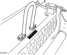
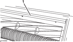
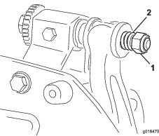
Whenever you need to tip the cutting unit to expose the bedknife/reel, prop up the rear of the cutting unit to ensure that the nuts on the back end of the bedbar-adjusting bolts are not resting on the work surface (Figure 18).

g016511

Relief-Grinding the Reel

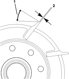
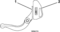
The new reel has a land width of 0.76 to 1.27 mm (0.030 to 0.050 inch) and a 30 degree relief grind.

When the land width gets larger than 3 mm (0.120 inch) wide, do the following:

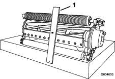
  1. Apply a 30 degree relief grind on all reel blades until the land width is 0.76 to 1.27 mm (0.030 to 0.050 inch) wide (Figure 19.

    g278332
  2. Spin grind the reel to achieve <0.025 mm (0.001 inch) reel run-out.

    Note: This causes the land width to grow slightly.

Note: To extend the longevity of the sharpness of the edge of the reel and the bedknife—after grinding the reel and/or the bedknife—check the reel to bedknife contact again after cutting 6 greens, as any burrs will be removed, which may create improper reel to bedknife clearance and thus accelerate wear.

Servicing the Bedbar

Only a properly trained mechanic should service the bedbar and bedknife to prevent damage to the reel, bedbar, or bedknife. Ideally, take the cutting unit to your authorized Toro distributor for service. Refer to the Service Manual for your traction unit for complete instructions, special tools, and diagrams for servicing the bedknife. Should you ever need to remove or assemble the bedbar yourself, instructions are provided below, as are the specifications for servicing the bedknife.

Important: Always follow the bedknife procedures detailed in your Service Manual when servicing the bedknife. Failure to install and grind the bed knife correctly can lead to damage to the reel, bedbar, or bedknife.
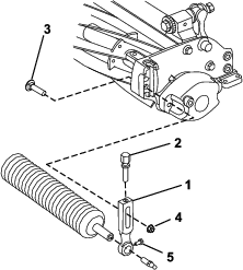
Removing the Bedbar

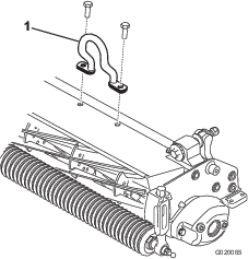
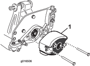
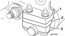
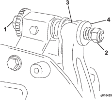
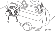
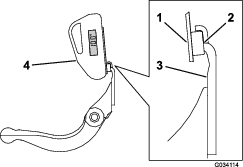
  1. Turn the bedbar adjusting screw, counterclockwise, to back the bedknife away from the reel (Figure 20).

    g016429
  2. Back out the spring-tension nut until the washer is no longer tensioned against the bedbar (Figure 20).

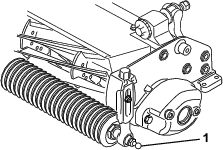
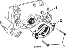
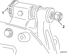
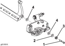
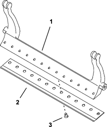
  3. On each side of the machine, loosen the locknut securing the bedbar bolt (Figure 21).

    g014409
  4. Remove each bedbar bolt allowing the bedbar to be pulled downward and removed from the cutting unit (Figure 21).

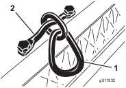
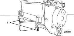
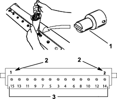
    Account for the 2 nylon washers and 1 steel washer on each end of the bedbar (Figure 22).

    g020056

Assembling the Bedbar

  1. Install the bedbar, positioning the mounting ears between the washers and the bedbar-adjusting screw (Figure 20).

  2. Secure the bedbar to each side plate with the bedbar bolts (nuts on bolts) and 3 washers (6 total).

  3. Position a nylon washer on each side of the side-plate boss. Place a steel washer outside each of the nylon washers (Figure 22).

  4. Torque the bedbar bolts to 27 to 36 N∙m (240 to 320 inch-lb).

  5. Tighten the locknuts until you remove the end play from steel washers, but you are able to rotate them by hand. The washers on the inside may have a gap.

    Important: Do not overtighten the locknuts or they will deflect the side plates.

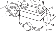
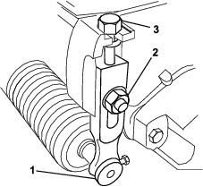
  6. Tighten the spring tension nut until the spring is collapsed, then back it off 1/2 turn (Figure 23).

    g016470
  7. Adjust the bedknife to the reel; refer to Adjusting the Bedknife-to-Reel Contact.

Checking the Top Grind Angle

The angle that you use to grind your bedknives is very important.

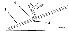
Use the angle indicator and the angle-indicator mount to check the angle that your grinder produces and then correct for any grinder inaccuracy.

  1. Place the angle indicator on the bottom side of the bedknife as shown in Figure 24.

    g034113
  2. Press the Alt Zero button on the angle indicator.

  3. Place the angle-indicator mount on the edge of the bedknife so that the edge of the magnet mates with the edge of the bedknife (Figure 25).

    Note: The digital display should be visible from the same side during this step as it was in step 1.

    g034114
  4. Place the angle indicator on the mount as shown in Figure 25.

    Note: This is the angle that your grinder produces, and should be within 2 degrees of the recommended top grind angle.

Reel Grinding Specifications

Reel Diameter (New)128.5 mm (5.06 inches)
Service Limit - Reel Diameter114.3 mm (4.50 inches)
Reel Shaft Diameter (OD)34.9 mm (1.375 inches)
Blade Relief Angle30°
Blade Relief Angle Range28–32°
Blade Land Width1 mm (0.040 inch)
Blade Land Width Range0.8 to 1.2 mm (0.030 to 0.050 inch)
Service Limit - Reel Diameter Taper0.25 mm (0.010 inch)

Installing the Bedknife

  1. Remove the rust, scale, and corrosion from the bedbar surface and apply a thin layer of oil to the bedbar surface.

  2. Clean the screw threads.

  3. Apply never-seize compound to the screws and install the bedknife to the bedbar.

    g255045
  4. Torque the 2 outer screws to 1 N∙m (10 in-lb).

  5. Working form the center of the bedknife, torque the screws to 23 to 28 N∙m (200 to 250 in-lb).

    g255046
  6. Grind the bedknife.

Backlapping the Cutting Unit

Danger

Contact with the reel or other moving parts can result in personal injury.

Keep your fingers, hands, and clothing away from the reels or other moving parts.

  • Stay away from the reel while backlapping.

  • Never use a short handled paint brush for backlapping. Part No. 29-9100 Handle assembly complete or individual parts are available from your local authorized Toro distributor.

  1. Position the machine on a clean, level surface, lower the cutting units, stop the engine, engage the parking brake, and remove the ignition key.

  2. Remove the reel motors from the cutting units and disconnect and remove the cutting units from the lift arms.

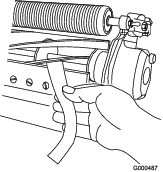
  3. Connect the backlapping machine to the cutting unit by inserting a piece of 3/8 inch square stock into the splined coupling in the end of the cutting unit.

    Note: Additional instructions and procedures on Backlapping are available in your traction unit Operator’s Manual and the Toro Sharpening Reel and Rotary Mowers Manual, Form Number 80-300PT.

    Note: For a better cutting edge, run a file across the front face of the bedknife and reel when the lapping operation is completed. This will remove any burrs or rough edges that may have built up on the cutting edge.