


Maintenance
Note: Determine the left and right sides of the machine from the normal operating position.
Maintenance Safety
Warning
While maintenance or adjustments are being made, someone could start the engine. Accidental starting of the engine could seriously injure you or other bystanders.
Remove the key from the ignition switch, engage parking brake, and pull the wire(s) off the spark plug(s) before you do any maintenance. Also push the wire(s) aside so it does not accidentally contact the spark plug(s).
Warning
The engine can become very hot. Touching a hot engine can cause severe burns.
Allow the engine to cool completely before service or making repairs around the engine area.
-
Park machine on level ground and allow the machine to cool. Never allow untrained personnel to service machine.
-
Disengage the spray or close the spreader gate, set the parking brake, stop engine and remove key or disconnect spark plug wire. Wait for all movement to stop before adjusting, cleaning or repairing.
-
Disconnect battery or remove spark plug wire before making any repairs. Disconnect the negative terminal first and the positive last. Reconnect positive first and negative last.
-
Relieve the spray pressure from the system before servicing.
-
Empty the tank and/or hopper before tilting the machine for maintenance and before storing.
-
Keep the machine, guards, shields and all safety devices in place and in safe working condition. Frequently check for worn or deteriorating components and replace them with the manufacturer’s recommended parts when necessary.
Warning
Removal or modification of original equipment, parts and/or accessories may alter the warranty, controllability, and safety of the machine. Unauthorized modifications to the original equipment or failure to use original Exmark parts could lead to serious injury or death. Unauthorized changes to the machine, engine, fuel or venting system, may violate applicable safety standards such as: ANSI, OSHA and NFPA and/or government regulations such as EPA and CARB.
Warning
Hydraulic fluid escaping under pressure can penetrate skin and cause injury. Fluid accidentally injected into the skin must be surgically removed within a few hours by a doctor familiar with this form of injury or gangrene may result.
-
If equipped, make sure all hydraulic fluid hoses and lines are in good condition and all hydraulic connections and fittings are tight before applying pressure to hydraulic system.
-
Keep body and hands away from pinhole leaks or nozzles that eject high pressure hydraulic fluid.
-
Use cardboard or paper, not your hands, to find hydraulic leaks.
-
Safely relieve all pressure in the hydraulic system by placing the motion control levers in neutral and shutting off the engine before performing any work on the hydraulic system.
-
-
Use jack stands to support components when required.
Caution
Raising the machine for service or maintenance relying solely on mechanical or hydraulic jacks could be dangerous. The mechanical or hydraulic jacks may not be enough support or may malfunction allowing the machine to fall, which could cause injury.
Do not rely solely on mechanical or hydraulic jacks for support. Use adequate jack stands or equivalent support.
-
Carefully release pressure from components with stored energy.
-
Keep hands and feet away from moving parts. If possible, Do Not make adjustments with the engine running. If the maintenance or adjustment procedure require the engine to be running and components moving, use extreme caution.
Warning
Contact with moving parts or hot surfaces may cause personal injury.
Keep your fingers, hands, and clothing clear of rotating components and hot surfaces.
-
Check all bolts frequently to maintain proper tightness.
Recommended Maintenance Schedule(s)
| Maintenance Service Interval | Maintenance Procedure |
|---|---|
| After the first 5 hours |
|
| After the first 100 hours |
|
| Before each use or daily |
|
| Every 50 hours |
|
| Every 80 hours |
|
| Every 100 hours |
|
| Every 500 hours |
|
| Monthly |
|
| Yearly |
|
Periodic Maintenance
Check Engine Oil Level
| Maintenance Service Interval | Maintenance Procedure |
|---|---|
| Before each use or daily |
|
-
Stop engine and wait for all moving parts to stop. Make sure unit is on a level surface.
-
Check with engine cold.
-
Clean area around dipstick. Remove dipstick and wipe oil off. Reinsert the dipstick according to the engine manufacturer's recommendations. Remove the dipstick and read the oil level.
-
If the oil level is low, wipe off the area around the oil fill cap, remove cap and fill to the “FULL” mark on the dipstick. Exmark 4-Cycle Premium Engine Oil is recommended; refer to the Engine Owner's manual for an appropriate API rating and viscosity. Do Not overfill.
Important: Do Not operate the engine with the oil level below the “LOW” (or “ADD”) mark on the dipstick, or over the “FULL” mark.
Check Battery Charge
| Maintenance Service Interval | Maintenance Procedure |
|---|---|
| Monthly |
|
Allowing batteries to stand for an extended period of time without recharging them will result in reduced performance and service life. To preserve optimum battery performance and life, recharge batteries in storage when the open circuit voltage drops to 12.4 volts.
Note: To prevent damage due to freezing, battery should be fully charged before putting away for winter storage.
Charge batteries in an open well ventilated area, away from spark and flames. Unplug charger before connecting or disconnecting from battery. Wear protective clothing and use insulated tools.
Danger
Charging or jump starting the battery may produce explosive gases. Battery gases can explode causing serious injury.
-
Keep sparks, flames, or cigarettes away from battery.
-
Ventilate when charging or using battery in an enclosed space.
-
Make sure venting path of battery is always open once battery is filled with acid.
-
Always shield eyes and face from battery.
Danger
Battery electrolyte contains sulfuric acid, which is poisonous and can cause severe burns. Swallowing electrolyte can be fatal or if it touches skin can cause severe burns.
-
Wear safety glasses to shield eyes, and rubber gloves to protect skin and clothing when handling electrolyte.
-
Do Not swallow electrolyte.
-
In the event of an accident, flush with water and call a doctor immediately.
Caution
If the ignition is in the “ON” position there is potential for sparks and engagement of components. Sparks could cause an explosion or moving parts could accidentally engage causing personal injury.
Be sure ignition switch is in the “OFF” position before charging the battery.
Check the voltage of the battery with a digital voltmeter. Locate the voltage reading of the battery in the table and charge the battery for the recommended time interval to bring the charge up to a full charge of 12.6 volts or greater.
Important: Make sure the negative battery cable is disconnected and the battery charger used for charging the battery has an output of 16 volts and 7 amps or less to avoid damaging the battery (see chart for recommended charger settings).
| Voltage Reading | Percent Charge | Maximum Charger Settings | Charging Interval |
|---|---|---|---|
| 12.6 or greater | 100% | 16 volts/7 amps | No Charging Required |
| 12.4 – 12.6 | 75–100% | 16 volts/7 amps | 30 Minutes |
| 12.2 – 12.4 | 50–75% | 16 volts/7 amps | 1 Hour |
| 12.0–12.2 | 25–50% | 14.4 volts/4 amps | 2 Hours |
| 11.7–12.0 | 0–25% | 14.4 volts/4 amps | 3 Hours |
| 11.7 or less | 0% | 14.4 volts/2 amps | 6 Hours or More |
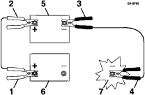
Recommended Jump Starting Procedure
-
Check the weak battery for terminal corrosion (white, green, or blue “snow”), it must be cleaned off prior to jump starting. Clean and tighten connections as necessary.
Caution
Corrosion or loose connections can cause unwanted electrical voltage spikes at anytime during the jump starting procedure.
Do Not attempt to jump start with loose or corroded battery terminals or damage to the engine may occur.
Danger
Jump starting a weak battery that is cracked, frozen, has low electrolyte level, or an open/shorted battery cell, can cause an explosion resulting in serious personal injury.
Do Not jump start a weak battery if these conditions exist.
-
Make sure the booster is a good and fully charged lead acid battery at 12.6 volts or greater. Use properly sized jumper cables (4 to 6 AWG) with short lengths to reduce voltage drop between systems. Make sure the cables are color coded or labeled for the correct polarity.
Caution
Connecting the jumper cables incorrectly (wrong polarity) can immediately damage the electrical system.
Be certain of battery terminal polarity and jumper cable polarity when hooking up batteries.
Note: The following instructions are adapted from the SAE J1494 Rev. Dec. 2001 – Battery Booster Cables – Surface Vehicle Recommended Practice (SAE – Society of Automotive Engineers).
Warning
Batteries contain acid and produce explosive gases.
-
Shield the eyes and face from the batteries at all times.
-
Do Not lean over the batteries.
Note: Be sure the vent caps are tight and level. Place a damp cloth, if available, over any vent caps on both batteries. Be sure the vehicles do not touch and that both electrical systems are off and at the same rated system voltage. These instructions are for negative ground systems only.
-
-
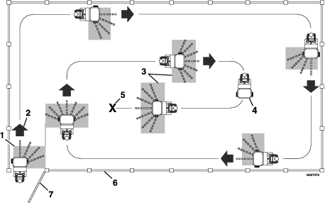
Connect the positive (+) cable to the positive (+) terminal of the discharged battery that is wired to the starter or solenoid as shown in .
-
Connect the other end of the positive cable to the positive terminal of the booster battery.
-
Connect the black negative (–) cable to the other terminal (negative) of the booster battery.
-
MAKE THE FINAL CONNECTION ON THE ENGINE BLOCK OF THE STALLED VEHICLE (NOT TO THE NEGATIVE POST) AWAY FROM THE BATTERY. STAND BACK.
-
Start the vehicle and remove the cables in the reverse order of connection (the engine block (black) connection is the first to disconnect).
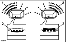
Check Safety Interlock System
| Maintenance Service Interval | Maintenance Procedure |
|---|---|
| Before each use or daily |
|
Important: It is essential that the operator safety mechanisms be connected and in proper operating condition prior to use.
Note: If the machine does not pass this test, do not operate. Contact your authorized Exmark Service Dealer.
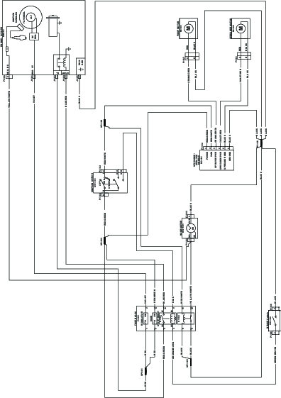
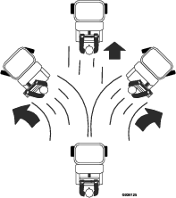
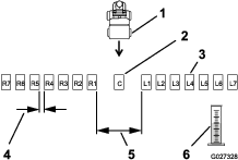
Check the Normal Engine Starting Circuit
| System | |||
| Parking Brake | Outcome | ||
| State of System | Engaged | Starter should crank | |
 |  |
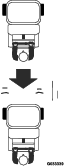
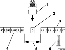
Check Engine Starting Circuit Chart
Note: In the Check Engine Starting Circuit Chart, the state of system item that is bold is being checked.
| System | |||
| Parking Brake | Outcome | ||
| State of System | Disengaged | Starter should not crank | |
 |  |
Check for Loose Hardware
| Maintenance Service Interval | Maintenance Procedure |
|---|---|
| Before each use or daily |
|
-
Stop engine, wait for all moving parts to stop, and remove key. Engage parking brake.
-
Visually inspect machine for any loose hardware or any other possible problem. Tighten hardware or correct the problem before operating.
Service Air Cleaner
| Maintenance Service Interval | Maintenance Procedure |
|---|---|
| Before each use or daily |
|
| Every 100 hours |
|
-
Stop engine, wait for all moving parts to stop, and remove key. Engage parking brake.
-
See the Engine Owner's Manual for maintenance instructions.
Change Engine Oil
| Maintenance Service Interval | Maintenance Procedure |
|---|---|
| After the first 5 hours |
|
| Every 100 hours |
|
-
Stop engine, wait for all moving parts to stop, and remove key. Engage parking brake.
-
Drain oil while engine is warm from operation.
-
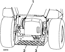
The oil drain valve is located on the left side of the engine.
Place pan under machine to catch oil. Rotate the valve hex nut to open and allow oil to drain and close the oil drain valve when complete.
-
Clean around oil fill cap and remove cap. Fill to specified capacity and replace cap.
-
Use oil recommended in the Check Engine Oil Level section. Do Not overfill. Start the engine and check for leaks. Stop engine and recheck oil level.
-
Wipe up any spilled oil from engine deck mounting surfaces.
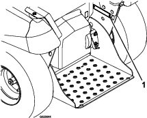
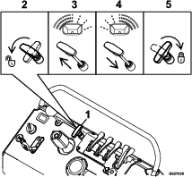
Check Transaxle Oil Overflow Tank Level
| Maintenance Service Interval | Maintenance Procedure |
|---|---|
| Every 50 hours |
|
-
Stop engine and wait for all moving parts to stop, and remove key. Engage parking brake.
-
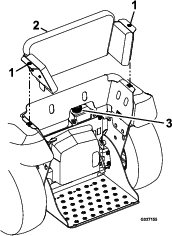
Turn the two knee pad quick release screws a quarter turn and pull upward to remove.
-
Clean area around oil overflow tank and remove cap. Oil level should be just over the bottom port in tank; if not, add Exmark Premium Hydro Oil.. Replace tank cap and tighten until snug. Do Not overtighten.
Check Tire Pressures
| Maintenance Service Interval | Maintenance Procedure |
|---|---|
| Every 50 hours |
|
-
Stop engine, wait for all moving parts to stop, and remove key. Engage parking brake.
-
Check tire pressure in drive tires.
-
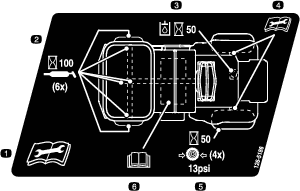
Inflate all tires to 13 psi (90 kPa).
Check Axle Bolt Torque
| Maintenance Service Interval | Maintenance Procedure |
|---|---|
| Yearly |
|
Torque the two axle bolts for the front wheels and the two axle bolts for the rear wheels to 35 ft-lb (48 N-m). Torque the setscrews at the rear hubs to 105 in-lb (12 N-m).
Important: If the wheel(s) are removed for maintenance, apply medium-grade thread-locking compound to the threads of the bolts before installing the wheel(s).
Important: If the rear wheel(s) are removed for maintenance, apply a copper-based, anti-seizing compound on the rear axle shafts.
Important: Do Not use anti-seize compound on the wheel bolts.
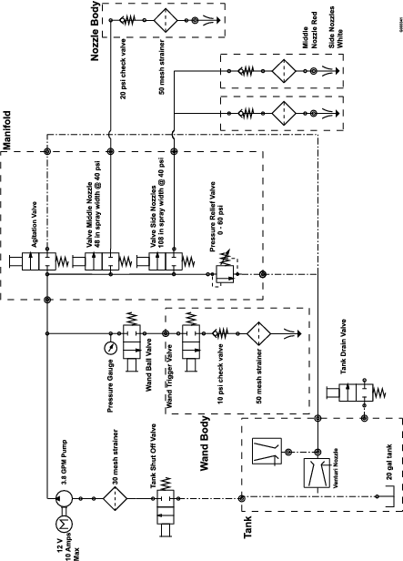
Check Sprayer System
| Maintenance Service Interval | Maintenance Procedure |
|---|---|
| Every 50 hours |
|
-
Stop engine, wait for all moving parts to stop, and remove key. Engage parking brake.
-
Check all hoses, nozzles, and fittings for leaks.
-
Check nozzle strainers and in-line strainers.
-
Replace as needed.
Check Fuel Strainer, Filter, and Tank
| Maintenance Service Interval | Maintenance Procedure |
|---|---|
| Before each use or daily |
|
-
Stop engine, wait for all moving parts to stop, and remove key. Engage parking brake.
-
Check the fuel strainer, filter, and tank for leaks. See Engine Owner's Manual.
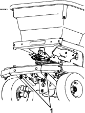
Lubricate Grease Fittings
| Maintenance Service Interval | Maintenance Procedure |
|---|---|
| Every 100 hours |
|
Note: See chart for service intervals.
-
Stop engine, wait for all moving parts to stop, and remove key. Engage parking brake.
-
Lubricate fittings with NLGI grade #2 multi-purpose gun grease.
Refer to the following chart for fitting locations and lubrication schedule.
Lubrication Chart
Fitting Locations Initial Pumps Number of Places Service Interval 1. Steering Pivots 1–2 6 Every 100 hours 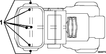
Check Spark Plugs
| Maintenance Service Interval | Maintenance Procedure |
|---|---|
| Every 100 hours |
|
Remove spark plugs, check condition and reset gaps, or replace with new plugs. See Engine Owner's Manual.
Clean Fuel Strainer, Filter, and Tank
| Maintenance Service Interval | Maintenance Procedure |
|---|---|
| Monthly |
|
-
Stop engine, wait for all moving parts to stop, and remove key. Engage parking brake.
-
Clean the fuel strainer, filter, and tank. See Engine Owner's Manual.
Wheel Mount Screw Torque Specification
| Maintenance Service Interval | Maintenance Procedure |
|---|---|
| After the first 100 hours |
|
| Every 500 hours |
|
Torque the screw on the wheel transaxle shaft to 35 ft-lb (48 N-m).
Check Spark Arrester
| Maintenance Service Interval | Maintenance Procedure |
|---|---|
| Every 50 hours |
|
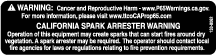
Warning
Hot exhaust system components may ignite gasoline vapors even after the engine is stopped. Hot particles exhausted during engine operation may ignite flammable materials. Fire may result in personal injury or property damage.
Do Not refuel or run engine unless spark arrester is installed.
-
Stop engine, wait for all moving parts to stop, and remove key. Engage parking brake.
-
Wait for muffler to cool.
-
If any breaks in the screen, welds, or deflector are observed, replace arrester.
-
If plugging of the screen is observed, remove arrester and shake loose particles out of the arrester and clean screen with a wire brush (soak in solvent if necessary). Reinstall arrester and deflector onto exhaust outlet.
Copper-Based Anti-seize
Copper based anti-seize is used in the following location:
On the rear axle shafts.
-
Apply each time the rear wheel(s) has been removed and reinstalled.
-
Apply yearly or before storage.
Adjustments
Steering Adjustment
-
Stop engine, wait for all moving parts to stop, and remove key. Engage parking brake.
-
Check the tire pressure (see Check Tire Pressures section).
-
Center and secure the steering control by placing a long bolt into the outside holes on the steering control and through the control column.
-
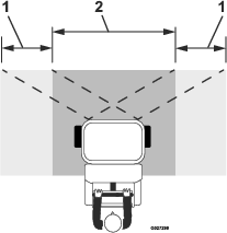
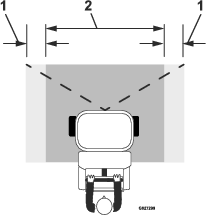
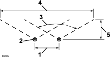
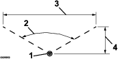
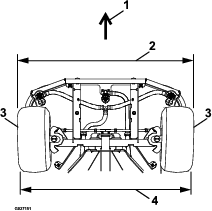
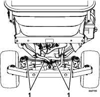
Measure the distance between the two front tires. Take one measurement from the front and rear as shown in Figure 34.
-
The front measurement should be approximately 1/4 inch (6.4 mm) larger than the rear measurement. If adjustment is needed:
-
Remove the front cover.
-
Loosen the jam nuts at the rod ends.
-
Rotate the steering rod to lengthen or shorten the linkage. Adjust both the LH and RH steering linkages equally.
Note: The factory center-to-center distance between the rod ball joint ends on the steering linkage is 9.21 inches (23.3 cm).
-
Tighten the jam nuts.
-
Reinstall the front cover.
-
-
Remove the long bolt from the steering control.
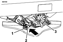
Spreader Pattern Control Cable Adjustment
To adjust the spreader pattern control cable:
-
Stop engine, wait for all moving parts to stop, and remove key. Engage parking brake.
-
Close the granular gate.
-
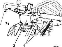
Make sure the spread pattern control handle is pushed down and locked at the control panel.
-
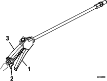
Loosen the jam nut at the end of the cable.
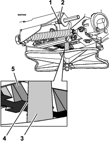
-
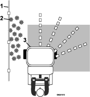
Pull the linkage rod until there is 1/8 inch (3.2 mm) gap between the ramp tooth and the impeller shaft.
-
Tighten the jam nut.
Cleaning
Clean Engine and Exhaust System Area
| Maintenance Service Interval | Maintenance Procedure |
|---|---|
| Before each use or daily |
|
Caution
Excessive debris around engine cooling air intake and exhaust system area can cause engine, exhaust area, and hydraulic system to overheat which can create a fire hazard.
Clean all debris from engine and exhaust system area.
-
Stop engine, wait for all moving parts to stop, and remove key. Engage parking brake.
-
Clean all debris from rotating engine air intake screen, around engine shrouding, and exhaust system area.
-
Wipe up any excessive grease or oil around the engine and exhaust system area.
-
Clean muffler heat shields of all debris, dirt, and oil.
Remove Engine Shrouds and Clean Cooling Fins
| Maintenance Service Interval | Maintenance Procedure |
|---|---|
| Every 80 hours |
|
-
Stop engine, wait for all moving parts to stop, and remove key. Engage parking brake.
-
Remove cooling shrouds from engine and clean cooling fins. Also clean dust, dirt, and oil from external surfaces of engine which can cause improper cooling.
-
Make sure cooling shrouds are properly reinstalled. Operating the engine without cooling shrouds will cause engine damage due to overheating.
Clean Debris From Machine
| Maintenance Service Interval | Maintenance Procedure |
|---|---|
| Before each use or daily |
|
-
Stop engine, wait for all moving parts to stop, and remove key. Engage parking brake.
-
Clean off any oil, debris, or build-up on the machine, especially the nozzles, tank opening, impeller, spray wand and its holder, around engine and exhaust area.
Important: You can wash the machine with mild detergent and water. Do not pressure wash the machine. Avoid excessive use of water, especially near the control panel, under the cushion, around the engine, hydraulic pumps, motors, and drive axle seals.
Waste Disposal
Chemical Disposal
Improper chemical disposal can pollute the environment and cause health issues.
Follow the disposal directions on the chemical manufacturer’s label. Dispose of chemicals and containers in accordance to local/state/federal laws.
Motor Oil Disposal
Engine oil and hydraulic oil are both pollutants to the environment. Dispose of used oil at a certified recycling center or according to your state and local regulations.
Battery Disposal
Danger
Battery electrolyte contains sulfuric acid, which is poisonous and can cause severe burns. Swallowing electrolyte can be fatal or if it touches skin can cause severe burns.
-
Wear safety glasses to shield eyes, and rubber gloves to protect skin and clothing when handling electrolyte.
-
Do Not swallow electrolyte.
-
In the event of an accident, flush with water and call a doctor immediately.
Federal law states that batteries should not be placed in the garbage. Management and disposal practices must be within relevant federal, state, or local laws.
If a battery is being replaced or if the unit containing the battery is no longer operating and is being scrapped, take the battery to a local certified recycling center. If no local recycling is available return the battery to any certified battery reseller.