| Maintenance Service Interval | Maintenance Procedure |
|---|---|
| Before each use or daily |
|
Introduction
This rotary-blade lawn mower is intended to be used by residential homeowners or professional, hired operators. It is designed primarily for cutting grass on well-maintained lawns on residential or commercial properties. Using this product for purposes other than its intended use could prove dangerous to you and bystanders.
Read this information carefully to learn how to operate and maintain your product properly and to avoid injury and product damage. You are responsible for operating the product properly and safely.
Visit www.Toro.com for more information, including safety tips, training materials, accessory information, help finding a dealer, or to register your product.
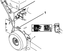
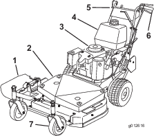
Whenever you need service, genuine Toro parts, or additional information, contact an Authorized Service Dealer or Toro Customer Service and have the model and serial numbers of your product ready. Figure 1 identifies the location of the model and serial numbers on the product. Write the numbers in the space provided.
Important: With your mobile device, you can scan the QR code on the serial number decal (if equipped) to access warranty, parts, and other product information.
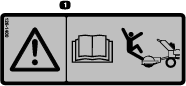
This manual identifies potential hazards and has safety messages identified by the safety-alert symbol (Figure 2), which signals a hazard that may cause serious injury or death if you do not follow the recommended precautions.

This manual uses 2 words to highlight information. Important calls attention to special mechanical information and Note emphasizes general information worthy of special attention.
It is a violation of California Public Resource Code Section 4442 or 4443 to use or operate the engine on any forest-covered, brush-covered, or grass-covered land unless the engine is equipped with a spark arrester, as defined in Section 4442, maintained in effective working order or the engine is constructed, equipped, and maintained for the prevention of fire.
The enclosed engine owner's manual is supplied for information regarding the US Environmental Protection Agency (EPA) and the California Emission Control Regulation of emission systems, maintenance, and warranty. Replacements may be ordered through the engine manufacturer.
Warning
CALIFORNIA
Proposition 65 Warning
The engine exhaust from this product contains chemicals known to the State of California to cause cancer, birth defects, or other reproductive harm.
Battery posts, terminals, and related accessories contain lead and lead compounds, chemicals known to the State of California to cause cancer and reproductive harm. Wash hands after handling.
Use of this product may cause exposure to chemicals known to the State of California to cause cancer, birth defects, or other reproductive harm.
Safety
This machine has been designed in accordance with ANSI B71.4-2017.
General Safety
This product is capable of amputating hands and feet and of throwing objects. Always follow all safety instructions to avoid serious personal injury.
-
Read, understand, and follow the instructions and warnings in this Operator’s Manual and on the machine and attachments before starting the engine.
-
Do not put your hands or feet near moving parts of or under the machine. Keep clear of any discharge opening.
-
Do not operate the machine without all guards and other safety protective devices in place and functioning properly on the machine.
-
Keep bystanders and children out of the operating area. Do not allow children to operate the machine. Allow only people who are responsible, trained, familiar with the instructions, and physically capable to operate the machine.
-
Stop the machine, shut off the engine, remove the ignition key (if equipped), and wait for all moving parts to stop before servicing, fueling, or unclogging the machine.
Improperly using or maintaining this machine can result in injury.
To reduce the potential for injury, comply with these safety instructions
and always pay attention to the safety-alert symbol  , which means
Caution, Warning, or Danger—personal safety instruction. Failure
to comply with these instructions may result in personal injury or
death.
, which means
Caution, Warning, or Danger—personal safety instruction. Failure
to comply with these instructions may result in personal injury or
death.
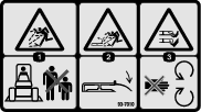
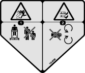
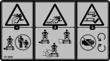
Safety and Instructional Decals
|
Safety decals and instructions are easily visible to the operator and are located near any area of potential danger. Replace any decal that is damaged or missing. |

.png)


Product Overview
Become familiar with all the controls before you start the engine and operate the machine.
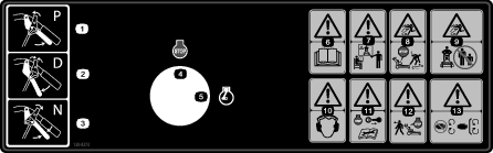
Control Panel
Throttle Control
The throttle control has 2 positions: FAST and SLOW (Figure 4).
Operator-Presence Control (OPC) Levers
When you squeeze the OPC levers (Figure 4) against the handles, the OPC system senses that you are in the normal operating position. When you release the OPC levers, the OPC system senses that you left the normal operating position, and the system shuts off the engine if either the gear-shift lever is not in the NEUTRAL position or the blade-control switch (power takeoff) is engaged.
Gear-Shift Lever
The gear-shift levels allows you to shift to 5 FORWARD positions, NEUTRAL position, and REVERSE position (Figure 4).
Note: It has an in-line shift pattern.
Important: Do not shift while the machine is moving, as you may damage the transmission.
Drive Levers
Release the drive levers to engage the forward traction operation. Squeeze the right drive lever to turn right or squeeze the left drive lever to turn left (Figure 4).
Neutral/Parking-Brake Lock
Squeeze the drive levers and move the locks rearward to the NEUTRAL-LOCK position. Squeeze the drive levers and move the locks forward to engage the parking brake (Figure 4).
Blade-Control Lever (Power Takeoff)
The blade-control lever, in conjunction with the OPC levers, engages and disengages power to the mower blades (Figure 4).
Recoil-Start Handle
Pull the recoil-start handle to start the engine (Figure 3).
Fuel-Shutoff Valve
Close the fuel-shutoff valve when transporting or storing the machine.
Key Switch
The key switch, used in conjunction with the recoil starter to start and shut off the engine, has 2 positions: RUN and OFF (Figure 4).
Choke
Use the choke to start a cold engine.
Note: Specifications and design are subject to change without notice.
| Width with deflector down | 116 cm (46 inches) |
| Length | 198 cm (78 inches) |
| Height | 104 cm (41 inches) |
| Weight | 182 kg (402 lb) |
| Width with deflector down | 118 cm (47 inches) |
| Length | 203 cm (80 inches) |
| Height | 104 cm (41 inches) |
| Weight | 210 kg (462 lb) |
| Width with deflector down | 161 cm (63-1/2 inches) |
| Length | 199 cm (78 inches) |
| Height | 104 cm (41 inches) |
| Weight | 227 kg (500 lb) |
Attachments/Accessories
A selection of Toro approved attachments and accessories is available for use with the machine to enhance and expand its capabilities. Contact your Authorized Service Dealer or authorized Toro distributor or go to www.Toro.com for a list of all approved attachments and accessories.
To ensure optimum performance and continued safety certification of the machine, use only genuine Toro replacement parts and accessories. Replacement parts and accessories made by other manufacturers could be dangerous, and such use could void the product warranty.
Operation
Note: Determine the left and right sides of the machine from the normal operating position.
Before Operation
Before Operation Safety
General Safety
-
Do not allow children or untrained people to operate or service the machine. Local regulations may restrict the age of the operator. The owner is responsible for training all operators and mechanics.
-
Become familiar with the safe operation of the equipment, operator controls, and safety signs.
-
Always shut off the machine, remove the ignition key (if equipped), wait for all moving parts to stop, and allow the machine to cool before adjusting, servicing, cleaning, or storing it.
-
Know how to stop the machine and shut off the engine quickly.
-
Check that operator-presence controls, safety switches, and safety protective devices are attached and functioning properly. Do not operate the machine unless they are functioning properly.
-
Inspect the area where you will use the machine, and remove all objects that could interfere with the operation of the machine or that the machine could throw.
-
Evaluate the terrain to determine what accessories and attachments are needed to properly and safely perform the job.
-
Before using, always visually inspect to see that the blades, blade bolts and mower deck are not worn or damaged. Replace worn or damaged blades and bolts in sets to preserve balance.
Fuel Safety
-
Use extreme care in handling fuel. It is flammable and its vapors are explosive.
-
Extinguish all cigarettes, cigars, pipes, and other sources of ignition.
-
Use only an approved fuel container.
-
Do not remove the fuel cap or add fuel to the tank while the engine is running or hot.
-
Do not add or drain fuel in an enclosed space.
-
Do not store the machine or fuel container where there is an open flame, spark, or pilot light, such as on a water heater or other appliance.
-
If you spill fuel, do not attempt to start the engine; avoid creating a source of ignition until the fuel vapors have dissipated.
-
Do not fill containers inside a vehicle or on a truck or trailer bed with a plastic liner. Always place containers on the ground, away from the vehicle before filling.
-
Remove equipment from the truck or trailer and refuel it on the ground. If this is not possible, refuel such equipment with a portable container rather than from a fuel-dispenser nozzle.
-
Keep the nozzle in contact with the rim of the fuel tank or container operating at all times until fueling is complete.
Adding Fuel
Recommended Fuel
-
For best results, use only clean, fresh (less than 30 days old), unleaded gasoline with an octane rating of 87 or higher ((R+M)/2 rating method).
-
Ethanol: Gasoline with up to 10% ethanol (gasohol) or 15% MTBE (methyl tertiary butyl ether) by volume is acceptable. Ethanol and MTBE are not the same. Gasoline with 15% ethanol (E15) by volume is not approved for use. Never use gasoline that contains more than 10% ethanol by volume, such as E15 (contains 15% ethanol), E20 (contains 20% ethanol), or E85 (contains up to 85% ethanol). Using unapproved gasoline may cause performance problems and/or engine damage which may not be covered under warranty.
-
Do not use gasoline containing methanol.
-
Do not store fuel either in the fuel tank or fuel containers over the winter unless you use a fuel stabilizer.
-
Do not add oil to gasoline.
Using Stabilizer/Conditioner
Use a fuel stabilizer/conditioner in the machine to provide the following benefits:
-
Keeps fuel fresh longer when used as directed by the fuel-stabilizer manufacturer
-
Cleans the engine while it runs
-
Eliminates gum-like varnish buildup in the fuel system, which causes hard starting
Important: Do not use fuel additives containing methanol or ethanol.
Add the correct amount of fuel stabilizer/conditioner to the fuel.
Note: A fuel stabilizer/conditioner is most effective when mixed with fresh fuel. To minimize the chance of varnish deposits in the fuel system, use fuel stabilizer at all times.
Filling the Fuel Tank
-
Park the machine on a level surface.
-
Engage the parking brake.
-
Shut off the engine and remove the key.
-
Clean around the fuel-tank cap.
-
Fill the fuel tank to the bottom of the filler neck.
Note: Do not fill the fuel tank completely full. The empty space in the tank allows the fuel to expand.
Performing Daily Maintenance
Before starting the machine each day, perform the Each Use/Daily procedures listed in .
During Operation
During Operation Safety
General Safety
-
The owner/operator can prevent and is responsible for accidents that may cause personal injury or property damage.
-
Wear appropriate clothing, including eye protection; long pants; substantial, slip-resistant footwear; and hearing protection. Tie back long hair and do not wear loose clothing or loose jewelry.
-
Use your full attention while operating the machine. Do not engage in any activity that causes distractions; otherwise, injury or property damage may occur.
-
Do not operate the machine while ill, tired, or under the influence of alcohol or drugs.
-
Before you start the engine, ensure that all drives are in neutral, the parking brake is engaged, and you are in the operating position.
-
Keep bystanders out of the operating area. Stop the machine if anyone enters the area.
-
Operate the machine only in good visibility and appropriate weather conditions. Do not operate the machine when there is the risk of lightning.
-
Wet grass or leaves can cause serious injury if you slip and contact the blade. Avoid mowing in wet conditions.
-
Keep your hands and feet away from the cutting unit.
-
Look behind and down before backing up to be sure of a clear path.
-
Use extreme care when approaching blind corners, shrubs, trees, or other objects that may block your view.
-
Disengage the drive to the cutting unit and shut off the engine before adjusting the height of cut.
-
Operate the engine only in well-ventilated areas. Exhaust gases contain carbon monoxide, which is lethal if inhaled.
-
Do not leave a running machine unattended.
-
Before leaving the operating position (including to empty the catchers or to unclog the cutting units), do the following:
-
Park the machine on level ground.
-
Disengage the cutting unit and lower the attachments.
-
Engage the parking brake.
-
Shut off the machine and remove the ignition key (if equipped).
-
Wait for all moving parts to stop.
-
Shut off the machine and disengage the drive to the cutting unit in the following situations:
-
Before fueling
-
Before clearing blockages
-
Before checking, cleaning, or maintaining the cutting unit
-
After striking a foreign object or if an abnormal vibration occurs. Inspect the cutting unit for damage and make repairs before starting and operating the machine
-
Before leaving the operating position
-
-
Use only accessories and attachments approved by The Toro® Company.
-
Be sure of your footing while using this machine, especially when backing up. Walk; do not run.
-
Never operate with the discharge deflector raised, removed or altered, unless you are using a grass catcher.
-
Never carry passengers on the machine.
-
Do not direct the discharge material toward anyone. Avoid discharging material against a wall or obstruction; material may ricochet toward you. Stop the blade(s) when crossing gravel surfaces.
-
Start the engine carefully according to instructions and with your feet well away from the blade(s) and not in front of the discharge chute.
-
Use extreme caution when reversing or pulling the machine toward you.
-
Stop the blade if you must transport the machine to and from the mowing area and when crossing surfaces other than grass.
-
Slope Safety
-
Slopes are a major factor related to loss of control and rollover accidents, which can result in severe injury or death. You are responsible for safe slope operation. Operating the machine on any slope requires extra caution. Before using the machine on a slope, do the following:
-
Review and understand the slope instructions in the manual and on the machine.
-
Evaluate the site conditions of the day to determine if the slope is safe for machine operation. Use common sense and good judgment when performing this evaluation. Changes in the terrain, such as moisture, can quickly affect the operation of the machine on a slope.
-
-
Operate across slopes, never up and down. Avoid operation on excessively steep or wet slopes. Poor footing could cause a slip-and-fall accident.
-
Identify hazards at the base of the slope. Do not operate the machine near drop-offs, ditches, embankments, water, or other hazards. The machine could suddenly roll over if a wheel goes over the edge or the edge collapses. Keep a safe distance between the machine and any hazard. Use a handheld tool to operate in these areas.
-
Avoid starting, stopping, or turning the machine on slopes. Avoid making sudden changes in speed or direction; turn slowly and gradually.
-
Do not operate a machine under any conditions where traction, steering or stability is in question. Be aware that operating the machine on wet grass, across slopes or downhill may cause the machine to lose traction. Loss of traction to the drive wheels may result in sliding and a loss of braking and steering. The machine can slide even if the drive wheels are stopped.
-
Remove or mark obstacles such as ditches, holes, ruts, bumps, rocks, or other hidden hazards. Tall grass can hide obstacles. Uneven terrain could overturn the machine.
-
If you lose control of the machine, step away from the direction of travel of the machine.
-
Always keep the machine in gear when going down slopes. Do not coast downhill (applicable only to gear-drive units).
Operating the Parking Brakes and Neutral Locks
Warning
Children or bystanders may be injured if they move or attempt to operate the machine while it is unattended.
Always park the machine on a level surface, engage the parking brake, and remove the ignition key if you leave the machine unattended.
Engaging the Parking Brakes
Disengaging the Parking Brakes
Engaging the Neutral Locks
Disengaging the Neutral Locks
-
Squeeze the drive levers rearward.
-
Place your thumbs on the upper part of the locks and move them forward until they are in the DRIVE position (Figure 5).
Starting the Engine
-
Connect the spark-plug wires.
-
Open the fuel valve.
-
Disengage the PTO and shift to the NEUTRAL position.
-
Engage the parking brakes.
-
Turn the ignition key to the RUN position.
-
To start a cold engine, move the throttle control midway between the FAST and SLOW positions.
-
To start a warm engine, move the throttle control to the FAST position.
-
-
Pull the choke knob if the engine is cold.
Note: A warm or hot engine usually does not require any choking.
-
Grasp the recoil-start handle firmly and pull it to start the engine.
Note: Allow the rope to recoil slowly.
Important: Do not pull the recoil rope to its limit or release the starter handle when you pull out the rope, because the rope may break or the recoil assembly may be damaged.
-
Push the choke to the OFF position as the engine warms up.
-
If the engine is cold, allow it to warm up and then move the throttle control to the FAST position.
Shutting Off the Engine
-
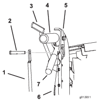
Move the throttle lever to the SLOW position (Figure 6).
-
Idle the engine for 30 to 60 seconds before turning the ignition key to the OFF position.
-
Engage the parking brakes and remove the ignition key.
-
Disconnect the spark-plug wires.
-
Close the fuel-shutoff valve.
Important: Ensure that you close the fuel-shutoff valve before transporting or storing the machine, as fuel may leak.
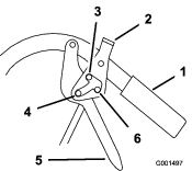
Operating the Blade-Control Lever (PTO)
The blade-control lever (PTO) engages and disengages power to the mower blades.
Engaging the Mower Blades
Disengaging the Mower Blades (PTO)
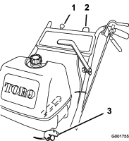
Pull the blade-control lever (PTO) fully rearward (Figure 7).
Note: The engine shuts off if you release the operator-presence control with the blade-control lever engaged.
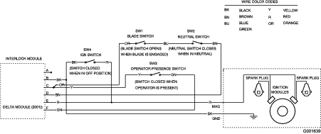
Using the Safety-Interlock System
Warning
If the safety-interlock switches are disconnected or damaged, the machine could operate unexpectedly, causing personal injury.
-
Do not tamper with the interlock switches.
-
Check the operation of the interlock switches daily and replace any damaged switches before operating the machine.
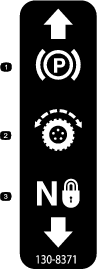
Understanding the Safety-Interlock System
The safety-interlock system is designed to prevent the engine from starting unless:
-
The PTO is disengaged.
-
The machine is in the NEUTRAL position.
-
The ignition key is in the RUN position.
The safety-interlock system is designed to shut off the engine when:
-
The operator-presence control (OPC) levers are released when the transmission or the blades are engaged.
-
The ignition key is turned to the OFF position.
-
The machine is shifted into gear without holding the OPC levers.
-
The blade-control lever (PTO) is engaged without holding the OPC levers.
Testing the Safety-Interlock System
Test the safety-interlock system each time before you use the machine. If the safety system does not operate as described, have an Authorized Service Dealer repair the safety system immediately.
-
Engage the parking brakes, move the shift lever to the NEUTRAL position, disengage the PTO, and move the throttle forward.
-
Start the engine.
-
Without holding the operator-presence control (OPC) levers, engage the blade-control lever (PTO).
The engine should shut off.
-
Disengage the blade-control lever (PTO).
-
With the engine running, hold down the OPC levers and engage the the blade-control lever (PTO).
The mower belt should engage and the mower blades should rotate.
-
Release the OPC levers.
The engine should shut off.
-
With the engine running, move the shift lever into gear and release the OPC levers.
The engine should shut off.
-
With the engine running, turn the ignition key to the OFF position.
The engine should shut off.
-
If all the above conditions are not met, have an Authorized Service Dealer repair the safety system immediately.
Driving the Machine
The throttle control regulates the engine speed (rpm). Move the throttle control to the FAST position for the best mowing performance.
Warning
The machine can spin very rapidly. You may lose control of the machine and cause personal injury or damage to the machine.
-
Use caution when making turns.
-
Slow the machine down before making sharp turns.
Driving Forward
-
Engage the parking brakes.
-
Squeeze the OPC levers against the handles.
-
Move the shift lever into a forward gear.
-
Disengage the parking brakes.
-
Slowly release the drive levers.
To go straight, release the drive levers equally. To turn, squeeze the drive lever on the same side as the direction you want to turn.
Driving Backward
-
Engage the parking brakes.
-
Squeeze the OPC levers against the handles.
-
Move the shift lever into the reverse gear.
-
Disengage the parking brakes.
-
Slowly release the drive levers.
Note: You must pull the mower backward to assist its rearward movement.
Stopping the Machine
Caution
You or bystanders may be injured if you move or attempt to operate the machine while it is unattended.
Always remove the ignition key and engage the parking brake if you leave the machine unattended.
-
Squeeze the drive levers back fully to engage the brakes.
-
Engage the parking brakes
-
Shift to the NEUTRAL position.
-
Move the throttle to the STOP position, and wait for all moving parts to stop before leaving the operating position.
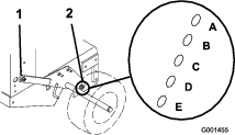
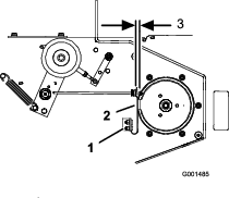
Adjusting the Flow Baffle
You can adjust the mower discharge flow for different types of mowing conditions. Position the cam lock and baffle for the best quality of cut.
-
Disengage the PTO and engage the parking brake.
-
Shut off the engine, remove the key, and wait for all moving parts to stop before leaving the operating position.
-
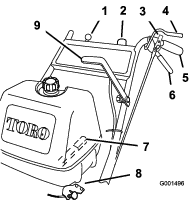
Loosen the nut (Figure 8).
-
Adjust the baffle and nut in the slot to the desired discharge flow.
-
Tighten the nut.
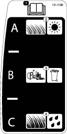
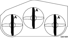
Positioning the Flow Baffle
The following figures are only recommendations for use. Adjustments vary by grass type, moisture content, and the height of the grass.
Note: If the engine power draws down and the mower ground speed is the same, open up the baffle.
Position A
This is the full rear position. The suggested use for this position is as follows:
-
Short, light grass mowing conditions
-
Dry conditions
-
Smaller grass clippings
-
Propels grass clippings farther away from the mower
Position B
Use this position when bagging.
Position C
This is the full open position. The suggested use for this position is as follows:
-
Tall, dense grass mowing conditions
-
Wet conditions
-
Lowers the engine-power consumption
-
Allows increased ground speed in heavy conditions
Side Discharging or Mulching Grass
This mower has a hinged grass deflector that disperses clippings to the side and down toward the turf.
Danger
Without the grass deflector, discharge cover, or complete grass catcher assembly mounted in place, you and bystanders are exposed to blade contact and thrown debris. Contact with rotating mower blade(s) and thrown debris can cause serious injury or death.
-
Never remove the grass deflector from the mower deck, because the grass deflector routes material down toward the turf. If the grass deflector is damaged, replace it immediately.
-
Never put your hands or feet under the mower deck.
-
Never try to clear the discharge area or mower blades before you disengage the mower blades. Turn the ignition key to the OFF position. Remove the key and disconnect the spark-plug wires.
Adjusting the Height of Cut
You can adjust the height of cut from 26 to 108 mm (1 to 4-1/4 inches) in 6 mm (1/4 inch) increments. You can achieve this by adjusting the blade spacers, rear axle height, or front caster spacers. Use the Height-of-Cut Chart to select the combination of adjustments required.
Adjusting the Blade Height
Adjust the blades by using the 4 spacers (6 mm or 1/4 inch) on the blade spindle bolts. This allows for a 25 mm (1 inch) adjustment range, in 6 mm (1/4 inch) increments, of cutting height in any axle position. Use the same number of blade spacers on all the blades to achieve a level cut (for example, 2 above and 2 below, 1 above and 3 below, etc.).
-
Park the machine on a level surface, disengage the PTO, and engage the parking brake.
-
Shut off the engine, remove the key, and wait for all moving parts to stop before leaving the operating position.
-
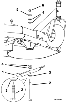
Hold the blade bolt and remove the nut (Figure 12).
-
Remove the blade bolt from the spindle and change the spacers as needed (Figure 12).
-
Install the blade bolt, curved washer, and extra spacers, and secure them with a thin washer and a nut (Figure 12).
-
Torque the blade bolt to 101 to 108 N∙m (75 to 80 ft-lb).
Adjusting the Axle Height
Adjust the axle position to the selected height-of-cut setting. Refer to the Height-of-Cut Chart.
-
Park the machine on a level surface, disengage the PTO, and engage the parking brake.
-
Shut off the engine, remove the key, and wait for all moving parts to stop before leaving the operating position.
-
Loosen, but do not remove, the 2 axle-pivot bolts and 2 axle-adjustment bolts (Figure 13).
-
Place a jack under the rear center of the engine frame. Raise the rear end of the engine frame up enough to remove the front 2 axle-adjustment bolts (Figure 13).
Note: Use jack stands to support the machine.
-
Raise or lower the engine frame with the jack so that you can install the front 2 axle-adjustment bolts in the desired hole location (Figure 13).
Note: Use a tapered punch to help align the holes.
-
Tighten all 4 bolts and lower the machine.
-
Adjust the control rods and brake linkages as required; refer to Adjusting the Control Rods and Adjusting the Parking Brake.
Important: You must adjust the control rods and brake linkage when you change the axle positions for proper traction and brake function.
Adjusting the Caster Position
-
Using the Height-of-Cut Chart, adjust the caster spacers to match with the axle hole selected (Figure 14).
-
Remove the latch pin, slide the caster from the support, and change the spacers (Figure 14).
-
Install the caster in the support and insert the latch pin (Figure 14).
Height-of-Cut Chart
| Axle position | Number of spacers below the caster | Number of 1/4-inch blade spacers below the spindle | |||||
| 13 mm (1/2 inch) | 5 mm (3/16 inch) | 4 | 3 | 2 | 1 | 0 | |
| A | 0 | 0 | 26 mm (1 inch) | 32 mm (1-1/4 inches) | 38 mm (1-1/2 inches) | 45 mm (1-3/4 inches) | 51 mm (2 inches) |
| A | 0 | 1 | 29 mm (1-1/8 inches) | 35 mm (1-3/8 inches) | 41 mm (1-5/8 inches) | 48 mm (1-7/8 inches) | 54 mm (2-1/8 inches) |
| A | 1 | 0 | 35 mm (1-3/8 inches) | 41 mm (1-5/8 inches) | 48 mm (1-7/8 inches) | 54 mm (2-1/8 inches) | 60 mm (2-3/8 inches) |
| B | 0 | 1 | 35 mm (1-3/8 inches) | 41 mm (1-5/8 inches) | 48 mm (1-7/8 inches) | 54 mm (2-1/8 inches) | 60 mm (2-3/8 inches) |
| B | 1 | 0 | 41 mm (1-5/8 inches) | 48 mm (1-7/8 inches) | 54 mm (2-1/8 inches) | 60 mm (2-3/8 inches) | 67 mm (2-5/8 inches) |
| B | 1 | 1 | 45 mm (1-3/4 inches) | 51 mm (2 inches) | 57 mm (2-1/4 inches) | 64 mm (2-1/2 inches) | 70 mm (2-3/4 inches) |
| B | 2 | 0 | 51 mm (2 inches) | 57 mm (2-1/4 inches) | 64 mm (2-1/2 inches) | 70 mm (2-3/4 inches) | 76 mm (3 inches) |
| C | 1 | 1 | 48 mm (1-7/8 inches) | 54 mm (2-1/8 inches) | 60 mm (2-3/8 inches) | 67 mm (2-5/8 inches) | 73 mm (2-7/8 inches) |
| C | 2 | 0 | 55 mm (2-1/8 inches) | 60 mm (2-3/8 inches) | 67 mm (2-5/8 inches) | 73 mm (2-7/8 inches) | 79 mm (3-1/8 inches) |
| C | 2 | 1 | 57 mm (2-1/4 inches) | 64 mm (2-1/2 inches) | 70 mm (2-3/4 inches) | 76 mm (3 inches) | 83 mm (3-1/4 inches) |
| C | 3 | 0 | 64 mm (2-1/2 inches) | 70 mm (2-3/4 inches) | 76 mm (3 inches) | 83 mm (3-1/4 inches) | 89 mm (3-1/2 inches) |
| D | 2 | 1 | 61 mm (2-3/8 inches) | 67 mm (2-5/8 inches) | 73 mm (2-7/8 inches) | 79 mm (3-1/8 inches) | 86 mm (3-3/8 inches) |
| D | 3 | 0 | 64 mm (2-1/2 inches) | 70 mm (2-3/4 inches) | 76 mm (3 inches) | 82 mm (3-1/4 inches) | 89 mm (3-1/2 inches) |
| D | 3 | 1 | 70 mm (2-3/4 inches) | 76 mm (3 inches) | 82 mm (3-1/4 inches) | 89 mm (3-1/2 inches) | 95 mm (3-3/4 inches) |
| D | 4 | 0 | 76 mm (3 inches) | 82 mm (3-1/4 inches) | 89 mm (3-1/2 inches) | 95 mm (3-3/4 inches) | 102 mm (4 inches) |
| E | 3 | 1 | 73 mm (2-7/8 inches) | 79 mm (3-1/8 inches) | 86 mm (3-3/8 inches) | 92 mm (3-5/8 inches) | 98 mm (3-7/8 inches) |
| E | 4 | 0 | 79 mm (3-1/8 inches) | 86 mm (3-3/8 inches) | 92 mm (3-5/8 inches) | 98 mm (3-7/8 inches) | 105 mm (4-1/8 inches) |
| E | 4 | 1 | 82 mm (3-1/4 inches) | 89 mm (3-1/2 inches) | 95 mm (3-3/4 inches) | 102 mm (4 inches) | 108 mm (4-1/4 inches) |
After Operation
After Operation Safety
General Safety
-
Always shut off the machine, remove the ignition key (if equipped), wait for all moving parts to stop, and allow the machine to cool before adjusting, servicing, cleaning, or storing it.
-
Clean grass and debris from the machine to help prevent fires. Clean up oil or fuel spills.
-
Never store the machine or fuel container where there is an open flame, spark, or pilot light, such as on a water heater or on other appliances.
-
Use full-width ramps for loading the machine into a trailer or truck.
-
Tie the machine down securely using straps, chains, cable, or ropes. Direct both front and rear straps down and outward from the machine.
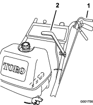
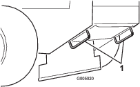
Transporting the Machine
Use a heavy-duty trailer or truck to transport the machine. Ensure that the trailer or truck has all the necessary brakes, lighting, and marking required by the law. Carefully read all the safety instructions.
-
If using a trailer, connect it to the towing vehicle and connect the safety chains.
-
If applicable, connect the trailer brakes.
-
Load the machine on to the trailer or truck.
-
Park the machine on a level surface, engage the parking brake, shut off the engine, remove the key, and close the fuel valve.
-
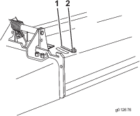
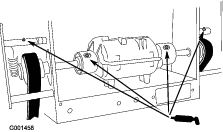
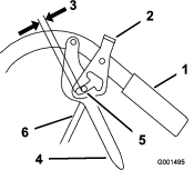
Use the tie-down loops on the machine to securely fasten the machine to the towing vehicle with straps, chains, cable, or ropes (Figure 15).
Maintenance
Note: Determine the left and right sides of the machine from the normal operating position.
Maintenance Safety
-
Before adjusting, cleaning, servicing, or leaving the machine, do the following:
-
Park the machine on a level surface.
-
Move the throttle switch to the low-idle position.
-
Disengage the cutting units.
-
Ensure that the transmission is in neutral.
-
Engage the parking brake.
-
Shut off the engine and remove the key.
-
Wait for all moving parts to stop.
-
Allow machine components to cool before performing maintenance.
-
-
Do not allow untrained personnel to service the machine.
-
If the engine must be running to perform a maintenance adjustment, keep your hands, feet, clothing, and any parts of the body away from the cutting unit, attachments, and any moving parts. Keep bystanders away.
-
Keep all parts in good working condition. Replace all worn, damaged, or missing parts and decals. Keep all fasteners tight to ensure that the machine is in safe working condition.
-
Check the grass catcher components frequently and replace them when they are worn or damaged.
-
Clean grass and debris from the cutting unit, drives, muffler, cooling screen, and the engine to help prevent fires. Clean up oil or fuel spills.
-
Check the brake operation frequently. Adjust and service the brake as needed.
-
Carefully release pressure from components with stored energy.
-
To ensure safe, optimal performance of the machine, use only genuine Toro replacement parts. Replacement parts made by other manufacturers could be dangerous, and such use could void the product warranty.
Recommended Maintenance Schedule(s)
| Maintenance Service Interval | Maintenance Procedure |
|---|---|
| After the first 8 hours |
|
| After the first 25 hours |
|
| Before each use or daily |
|
| Every 25 hours |
|
| Every 50 hours |
|
| Every 100 hours |
|
| Every 200 hours |
|
| Every 250 hours |
|
| Every 400 hours |
|
| Before storage |
|
Important: Refer to your engine owner's manual for additional maintenance procedures.
Caution
If you leave the key in the switch, someone could accidently start the engine and seriously injure you or other bystanders.
Shut off the engine and remove the key from the switch before you perform any maintenance.
Lubrication
Greasing the Machine
Grease the machine more often in dirty or dusty conditions.
Grease Type: No. 2 lithium or molybdenum grease
-
Park the machine on a level surface, disengage the blade-control switch (PTO), and engage the parking brake.
-
Shut off the engine, remove the key, and wait for all moving parts to stop before leaving the operating position.
-
Clean the grease fittings with a rag.
Note: Scrape any paint off the front of the fitting(s).
-
Pump grease into the fittings until grease begins to ooze out of the bearings.
-
Wipe up any excess grease.
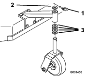
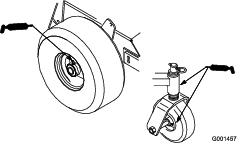
Lubricating the Caster and Wheel Bearings
| Maintenance Service Interval | Maintenance Procedure |
|---|---|
| Before each use or daily |
|
| Every 400 hours |
|
Greasing the Transmission Couplers
| Maintenance Service Interval | Maintenance Procedure |
|---|---|
| Every 250 hours |
|
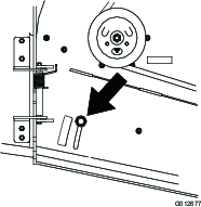
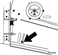
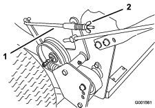
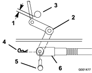
Lubricate the transmission couplers and idler-arm pivots located at the rear of the machine (Figure 17).
Greasing the Mower Belt Idler
| Maintenance Service Interval | Maintenance Procedure |
|---|---|
| Every 50 hours |
|
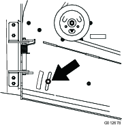
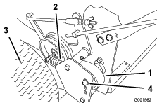
Grease the fitting on the mower belt idler arm pivot (Figure 18).
Note: Remove the mower deck cover to access the grease fitting for the mower belt idler arm.

Engine Maintenance
Engine Safety
-
Do not change the governor speed or overspeed the engine.
-
Run the engine dry or remove the fuel with a hand pump; never siphon the fuel. If you must drain the fuel tank, do it outdoors.
Servicing the Air Cleaner
| Maintenance Service Interval | Maintenance Procedure |
|---|---|
| Every 25 hours |
|
| Every 50 hours |
|
| Every 200 hours |
|
Note: Service the air cleaner more frequently (every few operating hours) if the operating conditions are extremely dusty or sandy.
Important: Do not apply oil to the foam or paper element.
Removing the Foam and Paper Elements
-
Park the machine on a level surface, disengage the PTO, and engage the parking brake.
-
Shut off the engine, remove the key, and wait for all moving parts to stop before leaving the operating position.
-
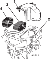
Clean the area around the air cleaner to prevent dirt from entering the engine and causing damage (Figure 20).
-
Unscrew the cover knobs and remove the air-cleaner cover (Figure 20).
-
Unscrew the hose clamp and remove the air-cleaner assembly (Figure 20).
-
Carefully pull the foam element off the paper element (Figure 20).
Cleaning the Foam Air-Cleaner Element
-
Wash the foam element in liquid soap and warm water. When the element is clean, rinse it thoroughly.
-
Dry the element by squeezing it in a clean cloth.
Important: Replace the foam element if it is torn or worn.
Servicing the Paper Air-Cleaner Element
Important: Do not clean the paper filter, replace it (Figure 20).
-
Inspect the element for tears, an oily film, or damage to the rubber seal.
-
Replace the paper element if it is damaged.
Installing the Foam and Paper Elements
Important: To prevent engine damage, always operate the engine with the complete foam and paper air-cleaner assembly installed.
Servicing the Engine Oil
Note: Change the oil more frequently when the operating conditions are extremely dusty or sandy.
Engine-Oil Specifications
Engine-Oil Type: Detergent oil (API service SF, SG, SH, SJ, or SL)
Crankcase Capacity: 1.7 L (58 oz) with the filter removed; 1.5 L (51 oz) without the filter removed
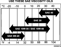
Viscosity: Refer to the table (Figure 21).
Checking the Engine-Oil Level
| Maintenance Service Interval | Maintenance Procedure |
|---|---|
| Before each use or daily |
|
-
Park the machine on a level surface, disengage the PTO, and engage the parking brake.
-
Shut off the engine, remove the key, and wait for all moving parts to stop before leaving the operating position.
-
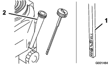
Clean around the oil dipstick (Figure 22) so that dirt cannot fall into the filler hole and damage the engine.
-
Unscrew the oil dipstick and wipe the end clean (Figure 22).
-
Slide the oil dipstick into the filler tube fully, but do not thread it onto the tube (Figure 22).
-
Pull the dipstick out and look at the end. If the oil level is low, slowly pour enough oil into the filler tube to raise the level to the Full mark.
Important: Do not overfill the crankcase with oil and run the engine, as this can damage the engine.
Changing the Engine Oil
| Maintenance Service Interval | Maintenance Procedure |
|---|---|
| After the first 8 hours |
|
| Every 100 hours |
|
| Every 200 hours |
|
-
Start the engine and let it run for 5 minutes.
-
Park the machine so that the drain side is slightly lower than the opposite side, to ensure that the oil drains completely.
-
Disengage the PTO and engage the parking brake.
-
Shut off the engine, remove the key, and wait for all moving parts to stop before leaving the operating position.
-
Slide the drain hose over the oil-drain valve.
-
Place a drain pan below the drain hose.
-
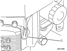
Rotate the oil-drain valve to allow the oil to drain (Figure 23).
-
After the oil drains completely, close the drain valve.
-
Remove the drain hose (Figure 23).
Note: Dispose the used oil at a recycling center.
-
Slowly pour approximately 80% of the specified oil into the filler tube (Figure 22).
-
Check the engine-oil level.
-
Slowly add the additional oil to bring it to the Full mark.
Changing the Engine-Oil Filter
Note: Change the engine-oil filter more frequently when the operating conditions are extremely dusty or sandy.
-
Drain the oil from the engine.
-
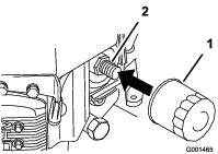
Remove the old filter (Figure 24).
-
Apply a thin coat of new oil to the rubber gasket on the replacement filter (Figure 24).
-
Install the replacement oil filter to the filter adapter, turn the oil filter clockwise until the rubber gasket contacts the filter adapter, and tighten the filter an additional 3/4 turn (Figure 24).
-
Fill the crankcase with the proper type of new oil.
-
Run the engine for approximately 3 minutes, shut off the engine, and check for oil leaks around the oil filter and drain valve.
-
Check the engine-oil level and add oil, if needed.
-
Wipe up any spilled oil.
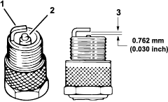
Servicing the Spark Plugs
| Maintenance Service Interval | Maintenance Procedure |
|---|---|
| Every 100 hours |
|
Type: Champion RCJ8Y (or equivalent)
Air Gap: 0.762 mm (0.03 inch)
Important: A cracked, fouled, dirty, or malfunctioning spark plug must be replaced. Do not sand-blast, scrape, or clean electrodes by using a wire brush because grit may eventually release from the plug and fall into the cylinder. The result is usually a damaged engine.
Note: The plug should be removed and checked whenever the engine malfunctions.
Removing the Spark Plugs
-
Park the machine on a level surface, disengage the PTO, and engage the parking brake.
-
Shut off the engine, remove the key, and wait for all moving parts to stop before leaving the operating position.
-
Disconnect the spark-plug wires (Figure 25).
-
Clean around the spark plugs to prevent dirt from entering the engine and potentially causing damage.
-
Remove the spark plugs and the washers.
Checking the Spark Plugs
-
Look at the center of the spark plugs (Figure 26).
Note: If you see light brown or gray on the insulator, the engine is operating properly. A black coating on the insulator usually means that the air cleaner is dirty.
-
If needed, clean the spark plug with a wire brush to remove carbon deposits.
Important: Always replace the spark plugs when it has worn electrodes, an oily film on it, or has cracks in the porcelain.
-
Check the gap between the center and side electrodes (Figure 26).
Note: Bend the side electrode (Figure 26) if the gap is not correct.
Installing the Spark Plugs
-
Install the spark plugs and the metal washer. Ensure that the air gap is set correctly.
-
Tighten the spark plugs to 22 N∙m (16 ft-lb).
-
Install the spark-plug wire (Figure 26).
Fuel System Maintenance
Danger
In certain conditions, fuel is extremely flammable and highly explosive. A fire or explosion from fuel can burn you and others and can damage property.
Refer to Adding Fuel for a complete list of fuel related precautions.
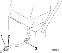
Servicing the Fuel System
Draining the Fuel Tank
-
Park the machine on a level surface, disengage the PTO, and engage the parking brake.
-
Shut off the engine, remove the key, and wait for all moving parts to stop before leaving the operating position.
-
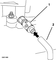
Close the fuel-shutoff valve at the fuel tank (Figure 27).
-
Squeeze the ends of the hose clamp together and slide it up the fuel line away from the fuel filter (Figure 27).
-
Pull the fuel line off the fuel filter (Figure 27).
-
Open the fuel-shutoff valve and allow the fuel to drain into a fuel container or drain pan.
Note: Now is the best time to install a new fuel filter, because the fuel tank is empty; refer to Replacing the Fuel Filter.
-
Install the fuel line to the fuel filter.
Slide the hose clamp close to the valve to secure the fuel line.
-
Wipe up any spilled fuel.
Replacing the Fuel Filter
| Maintenance Service Interval | Maintenance Procedure |
|---|---|
| Every 200 hours |
|
Important: Never install a dirty filter if it is removed from the fuel line.
-
Park the machine on a level surface, disengage the PTO, and engage the parking brake.
-
Shut off the engine, remove the key, and wait for all moving parts to stop before leaving the operating position.
-
Close the fuel-shutoff valve at the fuel tank (Figure 27).
-
Squeeze the ends of the hose clamps together and slide them away from the filter (Figure 28).
-
Remove the filter from the fuel lines.
-
Install a new filter and move the hose clamps close to the filter.
-
Open the fuel-shutoff valve at the fuel tank (Figure 27).
-
Check for fuel leaks and repair, if needed.
-
Wipe up any spilled fuel.
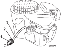
Servicing the Fuel-Vent System
| Maintenance Service Interval | Maintenance Procedure |
|---|---|
| Every 200 hours |
|
-
Park the machine on a level surface, disengage the PTO, and engage the parking brake.
-
Shut off the engine, remove the key, and wait for all moving parts to stop before leaving the operating position.
-
Remove the existing fuel-vent filter (Figure 29).
-
Install a new fuel-vent filter.

Electrical System Maintenance
Electrical System Safety
-
Disconnect the battery before repairing the machine. Disconnect the negative terminal first and the positive last. Connect the positive terminal first and the negative last.
-
Charge the battery in an open, well-ventilated area, away from sparks and flames. Unplug the charger before connecting or disconnecting the battery. Wear protective clothing and use insulated tools.
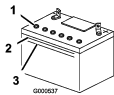
Servicing the Battery
Battery voltage: 12 V with 300 A (cold-cranking) at -18°C (0°F).
-
Always keep the battery clean and fully charged.
-
If the battery terminals are corroded, clean them with a solution of 4 parts water and 1 part baking soda.
-
Apply a light coating of grease to the battery terminals to prevent corrosion.
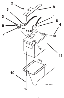
Removing the Battery
Warning
Incorrect battery cable routing could damage the machine and cables, causing sparks. Sparks can cause the battery gasses to explode, resulting in personal injury.
-
Always disconnect the negative (black) battery cable before disconnecting the positive (red) cable.
-
Always connect the positive (red) battery cable before connecting the negative (black) cable.
-
Always keep the battery strap in place to protect and secure the battery.
Warning
Battery terminals or metal tools could short against metal machine components, causing sparks. Sparks can cause the battery gasses to explode, resulting in personal injury.
-
When removing or installing the battery, do not allow the battery terminals to touch any metal parts of the machine.
-
Do not allow metal tools to short between the battery terminals and metal parts of the machine.
-
Park the machine on a level surface, disengage the PTO, and engage the parking brake.
-
Shut off the engine, remove the key, and wait for all moving parts to stop before leaving the operating position.
-
Remove the black rubber cover from the negative cable and disconnect the negative battery cable from the negative (-) battery terminal (Figure 30).
-
Slide the red terminal boot off the positive (+) battery terminal, and remove the positive battery cable (Figure 30).
-
Remove the battery hold-down plate (Figure 30) and remove the battery.
Installing the Battery
-
Place the battery in the machine (Figure 30).
-
Secure the battery with the hold-down plate, j-bolts, and locknuts (Figure 30).
-
Install the positive (red) battery cable to positive (+) battery terminal with a nut, washer, and bolt (Figure 30).
-
Slide the rubber cover over the post.
-
Install the negative battery cable and ground wire to the negative (-) battery terminal with a nut, washer, and bolt (Figure 30).
-
Slide the rubber cover over the post.
Checking the Battery Electrolyte Level
| Maintenance Service Interval | Maintenance Procedure |
|---|---|
| Every 25 hours |
|
Danger
Battery electrolyte contains sulfuric acid which is a deadly poison and causes severe burns.
-
Do not drink electrolyte and avoid contact with skin, eyes or clothing. Wear safety glasses to shield your eyes and rubber gloves to protect your hands.
-
Fill the battery where clean water is always available for flushing the skin.
-
Look at the side of the battery. The electrolyte must be at the upper line (Figure 31).
Do not allow the electrolyte to fall below the lower line (Figure 31).
-
If the electrolyte is low, add the required amount of distilled water; refer to Adding Water to the Battery.
Adding Water to the Battery
The best time to add distilled water to the battery is just before you operate the machine. This lets the water mix thoroughly with the electrolyte solution.
-
Remove the battery from the machine; refer to Removing the Battery.
Important: Never fill the battery with distilled water while the battery is installed in the machine. Electrolyte could be spilled on other parts and cause corrosion.
-
Clean the top of the battery with a paper towel.
-
Remove the vent caps from the battery (Figure 31).
-
Slowly pour distilled water into each battery cell until the electrolyte level is up to the upper line (Figure 31) on the battery case.
Important: Do not overfill the battery because electrolyte (sulfuric acid) can cause severe corrosion and damage to the machine.
-
Wait for 5 to 10 minutes after filling the battery cells.
-
Add distilled water, if necessary, until the electrolyte level is up to the upper line (Figure 31) on the battery case.
-
Install the battery vent caps.
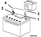
Charging the Battery
Warning
Charging the battery produces gasses that can explode.
Never smoke near the battery and keep sparks and flames away from battery.
Important: Always keep the battery fully charged (1.260 specific gravity). This is especially important to prevent battery damage when the temperature is below 0°C (32°F).
-
Remove the battery from the machine; refer to Removing the Battery.
-
Check the electrolyte level; refer to Checking the Battery Electrolyte Level.
-
Ensure that the filler caps are installed.
-
Connect a 3 to 4 A battery charger to the battery posts. Charge the battery at a rate of 3 to 4 A for 4 to 8 hours (12 V).
Note: Do not overcharge the battery.
-
When the battery is fully charged, unplug the charger from the electrical outlet, and disconnect the charger leads from the battery posts (Figure 32).
-
Install the battery; refer to Installing the Battery.
Storing the Battery
If you are storing the machine for more than 30 days, remove the battery and charge it fully. Either store it on the shelf or on the machine. Leave the cables disconnected if it is stored on the machine. Store the battery in a cool atmosphere to avoid quick deterioration of the charge in the battery. To prevent the battery from freezing, make sure that it is fully charged.
Drive System Maintenance
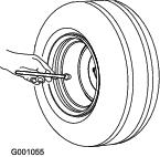
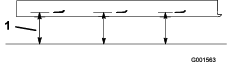
Checking the Tire Pressure
| Maintenance Service Interval | Maintenance Procedure |
|---|---|
| Every 50 hours |
|
Maintain the air pressure in the rear tires at 83 to 97 kPa (12 to 14 psi). Uneven tire pressure can cause an uneven cut (Figure 33).
Note: The front tires are semi-pneumatic tires and do not require air-pressure maintenance.
Cooling System Maintenance
Cleaning the Air-Intake Screen
| Maintenance Service Interval | Maintenance Procedure |
|---|---|
| Before each use or daily |
|
Remove any buildup of grass, dirt, or other debris from the cylinder and cylinder head cooling fins, the air-intake screen on the flywheel end, and the carburetor-governor levers and linkage. This helps ensure adequate cooling and correct engine speed to reduce the possibility of overheating or mechanical damage to the engine.
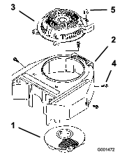
Cleaning the Cooling System
| Maintenance Service Interval | Maintenance Procedure |
|---|---|
| Before each use or daily |
|
| Every 100 hours |
|
-
Park the machine on a level surface, disengage the PTO, and engage the parking brake.
-
Shut off the engine, remove the key, and wait for all moving parts to stop before leaving the operating position.
-
Remove the air-intake screen, recoil starter, and fan housing (Figure 34).
-
Clean the debris and grass from the engine parts.
-
Install the air-intake screen, recoil starter, and fan housing (Figure 34).
Brake Maintenance
Servicing the Parking Brake
Check the brakes on both a level surface and a slope.
Always engage the parking brake when you stop the machine or leave it unattended. If the parking brake does not hold securely, adjust it.
Checking the Parking Brake
| Maintenance Service Interval | Maintenance Procedure |
|---|---|
| Before each use or daily |
|
-
Park the machine on a level surface and disengage the PTO.
-
Shut off the engine, remove the key, and wait for all moving parts to stop before leaving the operating position.
-
Engage the parking brake.
Note: The wheels must lock when you try to push the machine forward.
-
If the wheels do not lock, adjust the brakes; refer to Adjusting the Parking Brake.
-
Disengage the brakes and move the neutral/brake locks to the NEUTRAL position.
Note: The wheels should rotate freely. If not, refer to Adjusting the Parking Brake.
Adjusting the Parking Brake
If the parking brakes do not hold securely, adjust them.
-
Check the brakes before you adjust them; refer to Checking the Parking Brake.
-
Disengage the parking brakes.
-
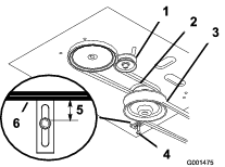
To adjust the brakes, rotate the wing nuts on the brake rods (Figure 35).
Rotate the wing nuts clockwise to tighten the brakes; rotate them counterclockwise to loosen them.
-
Position the wing nuts so that the brakes engage when you squeeze the drive levers enough to place the neutral/parking brake locks forward, and engage the brakes.
-
Check the operation of the brakes; refer to Checking the Parking Brake.
Important: When you disengage the parking brakes, the rear wheels should rotate freely when you push the machine. If they do not, contact an Authorized Service Dealer immediately.
-
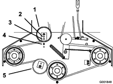
Check the control rod length, refer to Adjusting the Control Rods.
Belt Maintenance
Inspecting the Belts
| Maintenance Service Interval | Maintenance Procedure |
|---|---|
| Every 25 hours |
|
Replace the belt if it is worn. The signs of a worn belt include squealing while the belt is rotating; the blades slipping while cutting grass; and frayed edges, burn marks, and cracks on the belt.
Adjusting the Wheel Drive Belt Tension
You may need to increase the wheel drive belt tension under certain operating conditions, such as mowing over hilly terrain or while pulling a sulky.
-
Shut off the engine, remove the key, and wait for all moving parts to stop.
-
Disconnect the spark-plug wires.
-
Disengage the neutral/parking brake locks and release the drive levers to reduce the spring force.
-
Remove the drive spring from the adjustment bolt (Figure 36).
-
Remove the locknut securing the adjustment bolt to the drive pulley shield (Figure 36).
-
Locate the bolt assembly in the desired tension position as follows:
-
Position A for normal conditions
-
Position B for more severe conditions
-
Position C for the most severe conditions
Note: The wheel drive tension is lowest when the bolt assembly is in position A. The tension increases in positions B and C (Figure 36).
-
-
Install the adjustment bolt and the drive spring.
-
Repeat this procedure on the other side.
Replacing the Traction-Drive Belt
| Maintenance Service Interval | Maintenance Procedure |
|---|---|
| Every 50 hours |
|
-
Park the machine on a level surface, disengage the PTO, and engage the parking brake.
-
Shut off the engine, remove the key, and wait for all moving parts to stop before leaving the operating position.
-
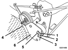
Remove the hairpin cotter securing the brake rod to the brake arm to relax the tension on the belt idler (Figure 37).
-
Remove the bottom bolt and loosen the top bolt of the shield to rotate it for belt clearance (Figure 37).
-
Lift the belt past the idler and off the drive pulley (Figure 37).
-
Raise the wheel off the ground enough to remove the belt.
-
Replace the traction-drive belt.
-
Secure the shield with the previously removed bolt and tighten the bolts (Figure 37).
-
Secure the brake rod to the brake arm with the hairpin cotter (Figure 37).
Replacing the Drive Belt
-
Park the machine on a level surface, disengage the PTO, and engage the parking brake.
-
Shut off the engine, remove the key, and wait for all moving parts to stop before leaving the operating position.
-
Raise the rear of the machine and hold it up with jack stands.
-
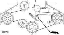
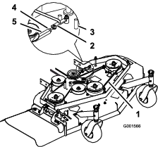
Remove the mower belt (Figure 38).
-
Loosen the pivot bolt enough to slide the idler pulley in the slot, and remove the traction belt from the engine and drive pulleys (Figure 38).
-
Install the new drive belt around the engine and drive pulleys (Figure 38).
-
Slide the idler pulley in the engine frame to tension the traction belt (Figure 38).
-
Install the mower belt (Figure 38).
-
Check the belt guide under the engine frame for the proper adjustment (Figure 38).
Note: The distance between the belt guide and mower belt should be 19 mm (3/4 inch) when you engage the mower belt. Adjust the belt, if necessary. The disengaged belt should not drag or fall off the pulley when the guides are properly adjusted.
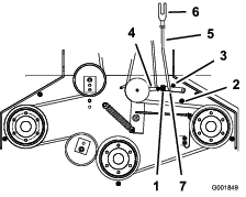
Replacing the Mower Belt
Important: The brake needs to be adjusted when the belt tension or the brake linkage is adjusted.
-
Park the machine on a level surface, disengage the PTO, and engage the parking brake.
-
Shut off the engine, remove the key, and wait for all moving parts to stop before leaving the operating position.
-
Remove the knobs and belt cover from the mower.
-
Remove the idler pulley and worn belt.
-
Install the new mower belt.
-
Install the idler pulley.
-
Engage the PTO and check the belt tension.
Note: The proper mower belt tension is 44 to 67 N∙m (10 to 15 ft-lb) with the belt deflected 13 mm (1/2 inch) halfway between the pulleys (Figure 42 or Figure 43).
-
Engage the PTO.
-
Check the clearance between the bell crank and transmission-output shaft (Figure 39).
Note: The clearance should be 2 to 3 mm (1/16 to 1/8 inch).
-
Remove the hairpin cotter and clevis pin from the bell crank (Figure 39).
-
Rotate the clevis clockwise on the rod to increase the clearance; rotate it counterclockwise to decrease it (Figure 39).
-
Disengage the PTO.
Note: If the assist arm does not contact the front stop on the mower deck (Figure 40 or Figure 41), adjust the clevis to bring the bell crank closer to the transmission-output shaft (Figure 39).

-
Check the belt guide under the engine frame for the proper adjustment (Figure 38).
Note: The distance between the belt guide and mower belt should be 32 mm (1-1/4 inches) when you engage the mower belt. Adjust the mower belt as necessary. The disengaged belt should not drag or fall off the pulley when the guides are properly adjusted.
Adjusting the Mower Belt Tension
Adjusting the Tension for 32-inch and 36-inch Mower Decks
| Maintenance Service Interval | Maintenance Procedure |
|---|---|
| After the first 8 hours |
|
| After the first 25 hours |
|
| Every 50 hours |
|
Important: Adjust the brake whenever you adjust the belt tension or brake linkage.
Important: The belt must be tight enough to not slip during heavy loads, while cutting grass. Over-tensioning the belt reduces the life of the spindle bearing, belt, and idler pulley.
The belt must be tight enough so that it does not slip during heavy loads while cutting grass, and over-tensioning will reduce belt and spindle bearing life.
-
Park the machine on a level surface, disengage the PTO, and engage the parking brake.
-
Shut off the engine, remove the key, and wait for all moving parts to stop before leaving the operating position.
-
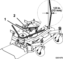
Loosen the locknut on the turnbuckle (Figure 42).
-
Adjust the tension of the belt.
-
Rotate the turnbuckle toward the rear of the machine to increase the tension on the belt.
-
Rotate the turnbuckle toward the front of the machine to decrease the tension on the belt (Figure 42).
Note: The eyebolt threads on both ends of the turnbuckle should be engaged a minimum of 8 mm (5/16 inch).
-
-
Engage the PTO and check the belt tension.
Adjust the tension until it is correct.
Note: The proper mower belt tension is 44 to 67 N∙m (10 to 15 ft-lb) with the belt deflected 13 mm (1/2 inch) halfway between the pulleys (Figure 42).
-
Tighten the locknut on the turnbuckle.
-
Check the adjustment of the blade brake; refer to Adjusting the Blade Brake.
Adjusting the Tension for 48-inch Mower Decks
Important: Adjust the brake whenever you adjust the belt tension or brake linkage.
Important: The belt must be tight enough to not slip during heavy loads, while cutting grass. Over-tensioning the belt reduces the life of the spindle bearing, belt, and idler pulley.
-
Park the machine on a level surface, disengage the PTO, and engage the parking brake.
-
Shut off the engine, remove the key, and wait for all moving parts to stop before leaving the operating position.
-
Loosen the locknut on the turnbuckle (Figure 44).
-
Adjust the tension of the belt.
-
Rotate the turnbuckle toward the rear of the machine to increase the tension on the belt.
-
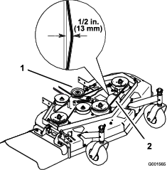
Rotate the turnbuckle toward the front of the machine to decrease the tension on the belt (Figure 43).
Note: The eyebolt threads on both ends of the turnbuckle should be engaged a minimum of 8 mm (5/16 inch).
-
-
Engage the PTO and check the belt tension.
Adjust the tension until it is correct.
Note: The proper mower belt tension is 44 to 67 N∙m (10 to 15 ft-lb) with the belt deflected 13 mm (1/2 inch) halfway between the pulleys (Figure 43).
-
If there is no adjustment remaining in the turnbuckle and the belt is still loose, the rear idler pulley needs to be positioned to the middle or front hole (Figure 45). Use the hole that provides the correct adjustment.
-
When you move the idler pulley, you must move the belt guide. Move the belt guide to the front position (Figure 45).
-
Check the belt guide under the engine frame for proper adjustment (Figure 46).
Note: The distance between the belt guide and the mower belt should be 19 mm (3/4 inch) when you engage the mower belt (Figure 46). Adjust the mower belt as necessary. The disengaged belt should not drag or fall off the pulley when the guides and belt tension are properly adjusted.
-
Check the adjustment of the blade brake; refer to Adjusting the Blade Brake.
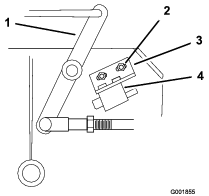
Adjusting the PTO-Engagement Linkage
The adjustment for the PTO-engagement linkage is located beneath the front, left corner of the engine deck.
-
Park the machine on a level surface, disengage the PTO, and engage the parking brake.
-
Shut off the engine, remove the key, and wait for all moving parts to stop before leaving the operating position.
-
Engage PTO.
-
Adjust the linkage length to where the lower end of the bellcrank just clears the axle-support gusset (Figure 47).
-
Ensure that the assist arm is against the rear assist-arm stop on the deck (Figure 48).
-
Disengage the PTO.
-
The assist arm should contact the front assist-arm stop on the deck. If it does not contact, adjust the bellcrank so that it is closer to the gusset (Figure 48).
-
To adjust the assist-arm link, remove the hairpin cotter from the assist arm (Figure 48).
-
Loosen the nut against the yoke (Figure 47).
-
Remove the assist-arm link from the assist arm and rotate the link to adjust the length.
-
Install the assist-arm link into the assist arm and secure it with the hairpin cotter (Figure 48).
-
Check if the assist arm hits against the stops correctly.
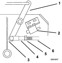
Adjusting the PTO-Safety Switch
-
Park the machine on a level surface, disengage the PTO, and engage the parking brake.
-
Shut off the engine, remove the key, and wait for all moving parts to stop before leaving the operating position.
-
Ensure that the assist arm is against the front assist-arm stop.
-
If needed, adjust the PTO-safety switch by loosening the bolts securing the switch bracket (Figure 49).
-
Move the mounting bracket until the bellcrank presses the plunger by 6 mm (1/4 inch).
Important: Ensure that the bellcrank does not touch the switch body; otherwise, damage to the switch could occur (Figure 49).
-
Tighten the switch-mounting bracket.
Controls System Maintenance
Adjusting the Control Rods
-
Park the machine on a level surface, disengage the PTO, and engage the parking brake.
-
Shut off the engine, remove the key, and wait for all moving parts to stop before leaving the operating position.
-
Remove the hairpin cotters and clevis pins from the drive levers and neutral locks (Figure 50).
-
Adjust the control rod length by threading the rod in or out of the rod fitting until there is a 5 to 6 mm (3/16 to 1/4 inches) clearance between the control rod and the bottom of the neutral/parking-brake lock (Figure 51).
-
Secure the control rod to the drive lever and neutral/parking-brake lock.
Secure the control rod with a clevis pin and hairpin cotter (Figure 51).
-
Check the operation of the control rod.
Note: If you need to adjust it, remove the hairpin cotter and clevis pin that secure the control rod to the drive levers.
-
Adjust the control rod length by repeating the previous steps.
Mower Deck Maintenance
Blade Safety
A worn or damaged blade can break and a piece could be thrown toward you or bystanders, resulting in serious personal injury or death.
-
Inspect the blades periodically for excessive wear or damage.
-
Use care when checking the blades. Wear gloves and use caution when servicing them. Only replace the blades; never straighten or weld them.
-
On multi-bladed machines, take care as rotating 1 blade can cause other blades to rotate.
Servicing the Cutting Blades
To ensure a superior quality of cut, keep the blades sharp. For convenient sharpening and replacement, you may want to keep extra blades on hand.
Before Inspecting or Servicing the Blades
-
Park the machine on a level surface, disengage the PTO, and engage the parking brake.
-
Shut off the engine, remove the key, and disconnect the spark-plug wires from the spark plugs.
Inspecting the Blades
| Maintenance Service Interval | Maintenance Procedure |
|---|---|
| Before each use or daily |
|
-
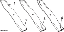
Inspect the cutting edges (Figure 52).
-
If the edges are not sharp or have nicks, remove and sharpen the blade; refer to Sharpening the Blades.
-
Inspect the blades, especially in the curved area.
-
If you notice any cracks, wear, or a slot forming in this area, immediately install a new blade (Figure 52).
Checking for Bent Blades
-
Rotate the blades until the ends face forward and backward (Figure 53).
-
Measure from a level surface to the cutting edge, position A, of the blades (Figure 55).
Note: Note this dimension.
-
Rotate the opposite ends of the blades forward.
-
Measure from a level surface to the cutting edge of the blades at the same position as in step 1.
Note: The difference between the dimensions obtained in steps 1 and 2 must not exceed 3 mm (1/8 inch). If this dimension exceeds 3 mm (1/8 inch), the blade is bent and must be replaced; refer to Removing the Blades and Installing the Blades.
Removing the Blades
Replace the blades if you hit a solid object or if the blades are out of balance or bent. To ensure optimum performance and continued safety conformance of the machine, use genuine Toro replacement blades. Replacement blades made by other manufacturers may result in non-conformance with safety standards.
-
Hold the blade bolt with a wrench.
-
Remove the nut, blade bolt, curved washer, blade, spacers, and thin washer from the spindle (Figure 56).
Sharpening the Blades
-
Use a file to sharpen the cutting edge at both ends of the blade (Figure 57).
Note: Maintain the original angle.
Note: The blade retains its balance if the same amount of material is removed from both cutting edges.

-
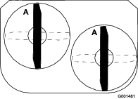
Check the balance of the blade by putting it on a blade balancer (Figure 58).
Note: If the blade stays in a horizontal position, the blade is balanced and can be used.
Note: If the blade is not balanced, file some metal off the end of the sail area only (Figure 57).

-
Repeat this procedure until the blade is balanced.
Installing the Blades
-
Install the curved washer and then the blade onto the bolt. Select the proper number of spacer(s) for the height of cut, and slide the bolt into the spindle (Figure 56).
Important: The curved part of the blade must point upward toward the inside of the mower to ensure proper cutting.
-
Install the remaining spacer(s) and secure them with a thin washer and a nut (Figure 56).
-
Torque the blade bolt to 101 to 108 N∙m (75 to 80 ft-lb).
Adjusting the Blade Brake
-
Park the machine on a level surface, disengage the PTO, and engage the parking brake.
-
Shut off the engine, remove the key, and disconnect the spark-plug wires from the spark plugs.
-
If necessary, adjust the spring-mounting bolts so that the blade-brake pad rubs against both sides of the pulley groove (Figure 59).
-
Adjust the nut at the end of the blade brake rod until there is 3 mm to 5 mm (1/8 to 3/16 inch) between the nut and spacer (Figure 59).
-
Engage the blades.
Note: Ensure that the blade-brake pad no longer contacts the pulley groove.
Replacing the Grass Deflector
Warning
An uncovered discharge opening could allow the machine to throw objects toward you or bystanders, resulting in serious injury. Also, contact with the blade could occur.
Never operate the machine without the grass deflector, the discharge cover, or the grass-collection system in place.
-
Park the machine on a level surface, disengage the PTO, and engage the parking brake.
-
Shut off the engine, remove the key, and disconnect the spark-plug wires from the spark plugs.
-
Remove the locknut, bolt, spring, and spacer securing the deflector to the pivot brackets (Figure 60).
Note: Remove the damaged or worn grass deflector.
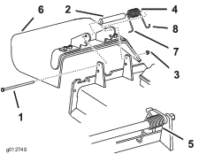
-
Place the spacer and spring onto the grass deflector.
-
Place the L-end of spring behind deck edge (Figure 60).
Note: Ensure that the L-end of the spring is installed behind the deck edge before installing the bolt as shown in Figure 60.
-
Install the bolt and nut.
-
Place the J-hook end of the spring around the grass deflector (Figure 60).
Important: The grass deflector must be able to rotate. Lift the deflector up to the fully-open position and ensure that it rotates into the fully-down position.
Cleaning
Cleaning under the Mower
| Maintenance Service Interval | Maintenance Procedure |
|---|---|
| Before each use or daily |
|
Remove the grass buildup under the mower daily.
-
Park the machine on a level surface, disengage the PTO, and engage the parking brake.
-
Shut off the engine, remove the key, and disconnect the spark-plug wires from the spark plugs.
-
Raise the front of the machine using a jack and use jack stands to support the machine.
-
Clean the machine with a rag. Do not spray the machine.
Disposing of Waste
Engine oil, batteries, hydraulic fluid, and engine coolant are pollutants to the environment. Dispose of these according to your state and local regulations.
Storage
Cleaning and Storing the Machine
-
Park the machine on a level surface, disengage the PTO, and engage the parking brake.
-
Shut off the engine, remove the key, and wait for all moving parts to stop before leaving the operating position.
-
Remove grass clippings, dirt, and grime from the external parts of the entire machine, especially the engine and hydraulic system.
Important: You can wash the machine with mild detergent and water. Do not pressure-wash the machine. Avoid excessive use of water, especially near the control panel, engine, hydraulic pumps, and motors.
-
Check the parking brake operation; refer to Checking the Parking Brake.
-
Service the air cleaner; refer to Servicing the Air Cleaner.
-
Grease the machine; refer to Lubrication.
-
Change the crankcase oil; refer to Servicing the Engine Oil.
-
Check the tire pressure; refer to Checking the Tire Pressure.
-
Charge the battery; refer to Charging the Battery.
-
Scrape any heavy buildup of grass and dirt from the underside of the mower, then wash the machine with a garden hose.
Note: Run the machine with the blade-control switch (PTO) engaged and the engine at high idle for 2 to 5 minutes after washing.
-
Check the condition of the blades; refer to Servicing the Cutting Blades.
-
Prepare the machine for storage for over 30 days as follows:
-
Add fuel stabilizer/conditioner to fresh fuel in the tank. Follow mixing instructions from the fuel stabilizer manufacturer. Do not use an alcohol-based stabilizer (ethanol or methanol).
-
Run the engine to distribute conditioned fuel through the fuel system for 5 minutes.
-
Shut off the engine, allow it to cool, and drain the fuel tank.
-
Start the engine and run it until it shuts off.
-
Dispose of fuel properly. Recycle the fuel according to local codes.
Important: Do not store fuel containing stabilizer/conditioner longer than the duration recommended by the fuel-stabilizer manufacturer.
-
-
Remove and check the condition of the spark plug(s); refer to Servicing the Spark Plugs. With the spark plug(s) removed from the engine, pour 30 ml (2 tablespoons) of engine oil into the spark plug hole. Use the starter to crank the engine and distribute the oil inside the cylinder. Install the spark plug(s). Do not install the wire on the spark plug(s).
-
Check and tighten all fasteners. Repair or replace any part that is damaged.
-
Paint all scratched or bare metal surfaces. Paint is available from your Authorized Service Dealer.
-
Store the machine in a clean, dry garage or storage area. Remove the key from the switch and keep it out of reach of children or other unauthorized users. Cover the machine to protect it and keep it clean.
Troubleshooting
| Problem | Possible Cause | Corrective Action |
|---|---|---|
| The fuel tank is showing signs of collapsing or the machine is frequently showing signs of running out of fuel. |
|
|
| The engine overheats. |
|
|
| The starter does not crank. |
|
|
| The engine does not start, starts hard, or fails to keep running. |
|
|
| The engine loses power. |
|
|
| The machine does not drive. |
|
|
| The machine vibrates abnormally. |
|
|
| The cutting height is uneven. |
|
|
| The blades do not rotate. |
|
|
Schematics
Electrical Schematic