Installation
Preparing the Machine
-
Park the machine on a level surface.
-
Engage the parking brake.
-
Shut off the machine and remove the key.
-
Disconnect the main negative battery cable (black) that connects the bank of batteries to the ground point of the machine; refer to your Operator’s Manual.
Replacing the Ignition Switch
Parts needed for this procedure:
| Ignition switch assembly | 1 |
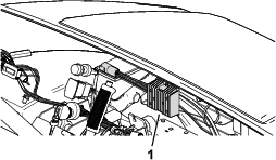
Removing the Existing Converter Module
Installing the Converter
Parts needed for this procedure:
| Converter | 1 |
| Converter bracket | 1 |
| Self-tapping screw (1/4 x 3/4 inch) | 6 |
| Relay | 1 |
| Hex-head screw (#6 x 1/2 inch) | 2 |
| Power-upgrade wire harness | 1 |
-
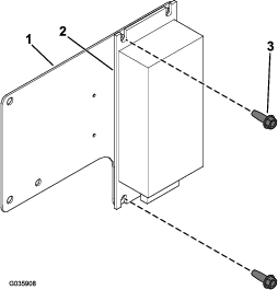
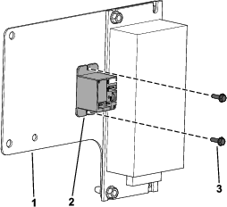
Install the left side of the converter to the converter bracket with 2 self-tapping screws (1/4 x 3/4 inch) as shown in Figure 4.
-
Install the relay to the converter bracket with the 2 hex-head screws (#6 x 1/2 inch) as shown in Figure 5.
-
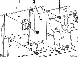
Install the converter bracket to the machine with 2 self-tapping screws (1/4 x 3/4 inch) on the left side of the bracket and 2 self-tapping screws (1/4 x 3/4 inch) to the right side of converter (Figure 6).
-
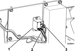
Connect the power-upgrade wire harness connections to the relay as follows:
-
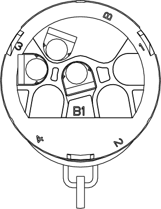
Connect the relay-coil wires (black with white stripe and orange) to the small terminals on the bottom of the relay (Figure 7).
-
Connect the relay-contact wires (green and blue) to the large terminals (Figure 7).
Note: The terminals are not polarity sensitive.
-
-
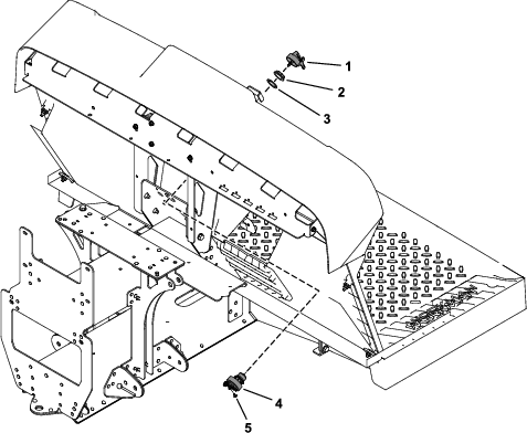
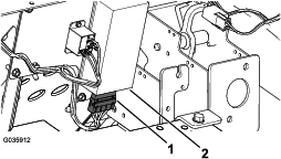
Connect the power-upgrade wire harness connector to the converter (Figure 8).
-
Connect the power-upgrade wire harness to the 48 V/12 V converter and the power-option connectors on the machine wire harness.
Installing the Fuse
Parts needed for this procedure:
| Fuse (20 A) | 1 |
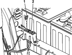
Install the fuse (20 A) into the slot in the fuse block (Figure 9).
Connecting the Battery
Connect the main negative-battery cable (black) that connects the bank of batteries to the ground point of the machine; refer to your Operator’s Manual.