Note: Determine the left and right sides of the machine from the normal operating position.
Safety
Safety and Instructional Decals
 |
Safety decals and instructions are easily visible to the operator and are located near any area of potential danger. Replace any decal that is damaged or missing. |
Installation
Note: The procedures for installing this kit require that you work from under the machine.
Preparing the Machine
Caution
If you leave the key in the ignition switch, someone could accidently start the engine and seriously injure you or other bystanders.
Remove the key from the ignition switch before you perform any maintenance.
Important: Use lifting and support equipment with a capacity of 1300 kg (5,000 lb) or greater.
Important: Cap or plug any disconnected hydraulic hoses, tubes, or component ports to prevent contaminating the system.
-
Park the machine on a level surface, engage the parking brake, be sure that the traction pedal is in the NEUTRAL position.
-
Ensure that the PTO button is in the OFF position.
-
Shut the engine off, remove the key from the switch, and allow the machine to cool.
-
Disconnect the negative cable from the battery post; refer to the Operator’s Manual for your machine.
Warning
Incorrect battery cable routing could damage the machine and cables, causing sparks. Sparks can cause the battery gasses to explode, resulting in personal injury.
-
Always disconnect the negative (black) battery cable before disconnecting the positive (red) cable.
-
Always connect the positive (red) battery cable before connecting the negative (black) cable.
-
-
Disconnect the positive battery cable from the battery; refer to the Operator’s Manual for your machine.
-
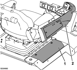
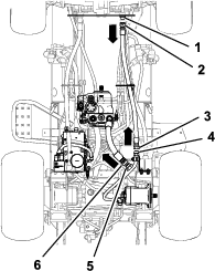
Remove the controller cover and the right console cover as shown in Figure 1.
-
Raise the machine using a hoist (preferred) or on jacks.
Note: Use jack stands or block the machine to prevent it from falling.
-
Bleed the pressure from the hydraulic system by turning the hydraulic pump bypass valve; refer to the pushing or towing the machine instructions in the Operator’s Manual.
Removing the Hydraulic Lines
Removing the Hydraulic Hoses
-
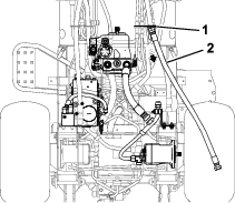
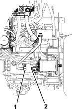
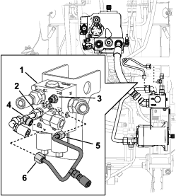
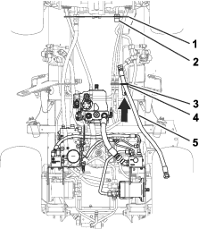
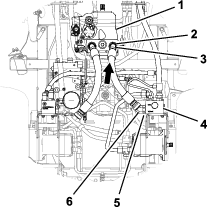
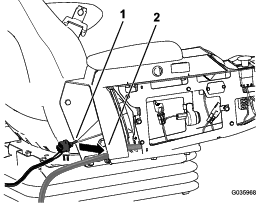
Align a drain pan below the forward end of the hydraulic-pressure hose (Figure 2).
-
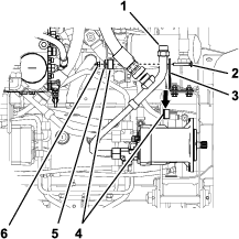
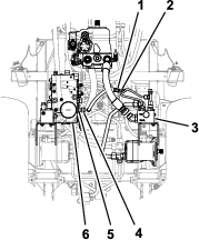
Remove the forward fitting of the hydraulic-pressure hose from the middle fitting of the divider tube, and allow the hydraulic fluid to drain from the hose and tube (Figure 3).
-
Temporarily plug the hydraulic-pressure hose.
-
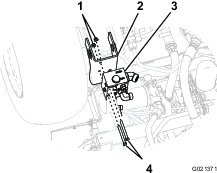
Remove the forward fitting of the rear traction hose from the rear fitting of the divider tube (Figure 3).
-
Remove the rear fitting of the rear traction hose from the bulkhead fitting in the bulkhead near the steering axle (Figure 3).
-
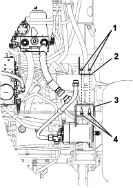
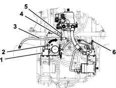
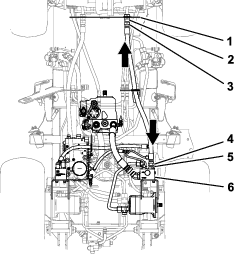
Pull the rear traction hose through the hose support bracket, and remove the hose from the machine (Figure 4).
Note: Discard the rear traction hose.
-
Temporarily cap the bulkhead fitting.
Removing the Tube Bracket and Clamp
-
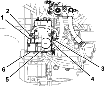
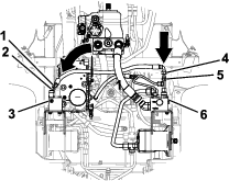
Remove the bolt, nut, and clamp plate securing the clamp-block halves and divider tube to the support bracket (Figure 5).
-
Remove the clamp-block halves (Figure 5).
-
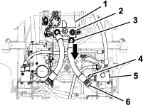
Remove the 2 bolts and 2 flange nuts that secure the support bracket to the chassis bracket, and remove the support bracket (Figure 6).
Note: Discard the bolts, nuts, clamp-block halves, and support bracket.
Removing the Divider Tube
-
Remove the tube nut of the divider tube from the T-fitting in the front, right traction motor, and remove the tube from the machine (Figure 7).
Note: Discard the divider tube.
-
Temporarily cap the T-fitting in the traction motor.
Removing the Traction-Control Hose
-
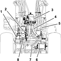
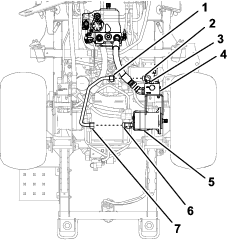
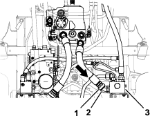
Remove the inboard-hose fitting for the traction-control hose from the hydraulic fitting in port (CH1) of the combination manifold (Figure 8).
-
Remove the outboard-hose fitting for the traction-control hose from the 45° hydraulic fitting in port (CH) of the rear traction manifold.
-
Temporarily cap the straight hydraulic fittings in the combination manifold and the 45° hydraulic fitting in the rear traction manifold.
Note: Discard the traction-control hose.
Installing the Hydraulic Components
Parts needed for this procedure:
| Flow divider | 1 |
| Hex-head bolt | 2 |
| Flange nut | 2 |
| Traction-motor tube | 1 |
| Tube manifold | 1 |
| Return hose | 1 |
| Cross hose | 1 |
| Rear traction hose | 1 |
Installing the Flow-Divider Manifold
-
Align the holes in the flow-divider manifold with the holes in the chassis bracket (Figure 9).
Note: Ensure that the 45º fitting in the flow-divider manifold is toward the center line of the machine.
-
Secure the flow-divider manifold to the chassis bracket with the 2 hex-head bolts and 2 flange nuts (Figure 9).
Installing the Traction-Motor Tube
-
Align the tube nuts for the traction-motor tube to the T-fitting in the traction motor and the 90º fitting in the flow divider (Figure 10).
Note: Ensure that the traction-motor tube is routed above the hydraulic-pressure hose of the hydraulic pump; refer to step 2 of Removing the Hydraulic Hoses.
Note: Rotate the 90º fitting as necessary to align the fitting with the rear tube nut of the traction-motor tube.
-
Remove the cap from the T-fitting of the traction motor that you installed step 2 of Removing the Traction-Control Hose.
-
Thread the tube nuts for the traction-motor tube onto the fittings in the traction motor and the flow divider (Figure 10).
-
Tighten the jam nut for the 90º fitting (Figure 10).
-
Tighten the tube nuts of the traction-motor tube to 116 to 142 N∙m (85 to 105 ft-lb).
Note: Ensure that there is clearance between all the hard lines, or they will rattle against each other during operation.
Installing the Tube Manifold
-
Align the forward tube nut for the tube manifold with the check adapter located in port CH1 of the flow divider (Figure 11).
-
Align the rear tube nut for the tube manifold with the 90° threaded fitting of the T-fitting (Figure 11).
Note: Rotate the T-fitting necessary to align the fitting with the rear tube nut of the tube manifold.
-
Thread the tube nuts of the tube manifold onto the check adapter and the T-fitting (Figure 11).
-
Tighten the tube nut of the T-fitting to 51 to 63 N∙m (37 to 47 ft-lb).
-
Tighten the tube nut of the tube manifold to 51 to 63 N∙m (37 to 47 ft-lb).
Installing the Return Hose
-
Align the straight fitting of the return hose with the threaded fitting of the tube manifold (Figure 12).
Note: Ensure that the return hose is routed above the hydraulic-pressure hose of the hydraulic pump; refer to step 2 of Removing the Hydraulic Hoses.
-
Align the 90° fitting of the return hose with the threaded fitting in the combination manifold (Figure 12).
-
Remove the cap from the hydraulic fitting in the combination manifold that you installed in step 3 of Removing the Traction-Control Hose.
-
Thread the hose fittings onto the fittings of the return manifold and the combination manifold, and tighten the hose fittings to 51 to 63 N∙m (37 to 47 ft-lb).
-
Torque the 90° fitting of the return hose to 51 to 63 N∙m (37 to 47 ft-lb).
-
Torque the straight fitting of the return hose to 37 to 44 N∙m (27 to 33 ft-lb).
Installing the Cross Hose
-
Align the 90° fitting of the cross hose through the cushioned guide in the support bracket, and slide the hose through the bracket (Figure 13).
-
Align the 90° fitting of the cross hose with the straight-threaded fitting of the T-fitting (Figure 14).
Note: Ensure that the cross hose is routed above the hydraulic-pressure hose of the hydraulic pump; refer to step 2 of Removing the Hydraulic Hoses.
-
Align the straight fitting of the cross hose with the 45° hydraulic fitting in the rear traction manifold (Figure 14).
-
Remove the cap from the 45° hydraulic fitting in the rear traction manifold that you installed in step 3 of Removing the Traction-Control Hose.
-
Thread the hose fittings of the cross hose onto the fittings of the T-fitting and the rear traction manifold, and tighten the fittings to 51 to 63 N∙m (37 to 47 ft-lb).
Installing the Rear Traction Hose
-
Align the fitting of the rear traction hose through the cushioned guide of the support bracket, and slide the hose through the bracket (Figure 15).
-
Align the rear fitting of the rear traction hose with the bulkhead fitting (Figure 16).
-
Align the forward fitting of the rear traction hose with the straight hydraulic fitting located in port M3 of the flow-divider manifold (Figure 16).
-
Remove the cap from the bulkhead fitting that you installed in step 3 of Removing the Hydraulic Hoses.
-
Thread the hose fittings of the rear traction hose onto the fittings in the flow-divider manifold and the bulkhead fitting, and tighten the fittings to 116 to 142 N∙m (85 to 105 ft-lb).
Installing the Hydraulic-Pressure Hose
-
Remove the plug from the end of the hydraulic-pressure hose that you installed in step 3 of Removing the Hydraulic Hoses.
-
Remove the 45° fitting of the pressure hose from the straight fitting in the hydraulic pump (Figure 17).
-
Align the straight fitting of the hydraulic-pressure hose with the 45° hydraulic fitting in the flow-divider manifold (Figure 18).
-
Thread the straight fitting of the hydraulic-pressure hose onto the 45° hydraulic fitting in the flow-divider manifold (Figure 18).
-
Align the 45° fitting of the pressure hose with the straight fitting in the hydraulic pump (Figure 19).
-
Thread the 45° fitting of the pressure hose onto the straight fitting in the hydraulic pump (Figure 19).
-
Tighten the jam nut of the 45° hydraulic fitting onto the flow-divider manifold (Figure 19).
-
Torque the straight and 45° fittings of the pressure-hose to 150 to 184 N∙m (110 to 136 ft-lb).
Installing the Switch
Parts needed for this procedure:
| Toggle switch | 1 |
| Wire harness | 1 |
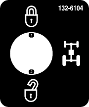
| 4WD function decal | 1 |
-
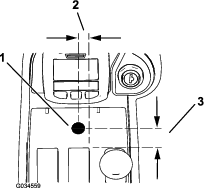
Drill a 13 mm (1/2 inch) hole in the center console; refer to Figure 20 for the appropriate orientation.
Important: Use caution to not hit any components or wires underneath the console with the drill bit.
-
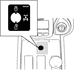
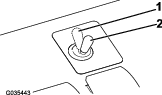
Place the 4WD function decal over the drilled hole (Figure 21).
-
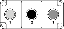
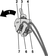
Identify the switch terminal locations, wire harness labels, and wire harness colors (Figure 22).
The switch terminals are identified by the numbers imprinted into the bottom of the switch.
Note: The switch is spring-loaded to the rear of the switch (Figure 23). The switch is normally open between terminals 1 and 2 (Figure 22).
-
Secure the red wire labeled BYPASS ENGAGE SWITCH 2 to the override switch center terminal number 2 (Figure 22 and Figure 23).
-
Secure the gray wire labeled BYPASS ENGAGE SWITCH 1 to the override switch rear terminal number 1 (Figure 22 and Figure 23).
Important: Incorrect switch wiring can result in damage to the hydraulic system. Verify that the wiring is installed correctly; refer to Testing the Flow-Divider Manifold.
-
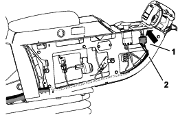
Route the toggle switch with the connected wire harness into the rear of the center console (Figure 24).
-
Pull the toggle switch/wire harness through the center console up to the drilled hole (Figure 25).
-
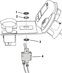
Install the toggle switch into the 13 mm (1/2 inch) hole from the bottom of the console; refer to Figure 26 for the correct hex locknut and washer orientation.
Note: Install the switch spring-loaded toward the rear of the machine.Discard the tabbed washer included with the toggle switch.
Installing the Kit to the Wire Harness
Parts needed for this procedure:
| Relay | 1 |
| Cable tie | 1 |
-
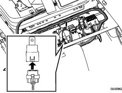
Plug the relay connector into the relay as shown in Figure 27.
-
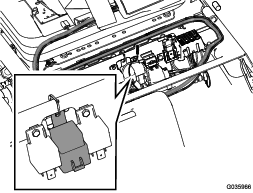
Connect the relay to the relay mount with a cable tie as shown in Figure 28.
-
Unlatch the seat and locate the remaining loose wire harness ends below the back right corner of the now exposed frame crossbar.
-
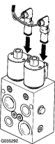
Plug the loose harness ends into the 4WD manifold just inside of the right, front tire (Figure 29).
Completing the Installation
Checking for Hydraulic Leaks
Warning
Hydraulic fluid escaping under pressure can penetrate skin and cause injury.
-
Make sure that all hydraulic fluid hoses and lines are in good condition and all hydraulic connections and fittings are tight before applying pressure to the hydraulic system.
-
Keep your body and hands away from pin hole leaks or nozzles that eject high-pressure hydraulic fluid.
-
Use cardboard or paper to find hydraulic leaks.
-
Safely relieve all pressure in the hydraulic system before performing any work on the hydraulic system.
-
Get immediate medical help if fluid is injected into skin.
-
Check and tighten all fittings and hydraulic connections.
-
Ensure that the hydraulic pump bypass valve is in the operation position; refer to the pushing or towing the machine instructions in the Operator’s Manual.
-
Check the hydraulic fluid level and replenish it as required.
-
Connect the positive battery cable to the positive post of the battery; refer to the Operator’s Manual for your machine.
Warning
Incorrect battery cable routing could damage the machine and cables causing sparks. Sparks can cause the battery gasses to explode, resulting in personal injury.
-
Always disconnect the negative (black) battery cable before disconnecting the positive (red) cable.
-
Always connect the positive (red) battery cable before connecting the negative (black) cable.
-
-
Connect the negative battery cable to the negative post of the battery; refer to the Operator’s Manual for your machine.
-
Close the right toolbox cover and install the right console cover (Figure 1).
-
Start the machine and allow the hydraulic system to pressurize.
-
Stop the engine and check the hydraulic tubes, hoses, and fittings for leaks.
Note: Repair all leaks before operating the machine.
Testing the Flow-Divider Manifold
-
Place the key into the switch, turn the key to the ON position, and disengage the parking brake.
-
Drive the machine forward and press the 4WD toggle switch forward.
Note: You should hear the solenoids shift if the kit is installed properly. If you do not, check the wire harness connections and fuse placement.
-
Make a tight turn with the switch pressed forward.
Note: You should feel the 4WD if the kit is installed properly. If you do not, check the wire harness connections and fuse placement.
Operation
4WD Switch
Press and hold the 4WD toggle switch forward to momentarily activate the 4WD function of the machine.
Operating Tips
The flow divider kit enhances the traction drive performance in compromised operating conditions.
Important: If both the front and rear wheels spin, feather the steering brake to control the transfer of the torque from the spinning wheels to the opposite front wheel.
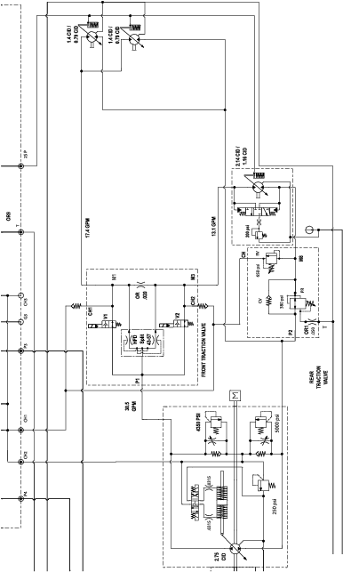
Schematics
Hydraulic Schematic