
 , which means Caution, Warning,
or Danger—personal safety instruction. Failure to comply with
these instructions may result in personal injury or death.
, which means Caution, Warning,
or Danger—personal safety instruction. Failure to comply with
these instructions may result in personal injury or death.


Maintenance
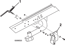
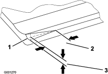
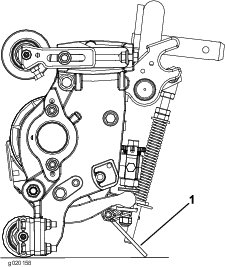
Using the Kickstand When Tipping the Cutting Unit
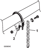
Whenever you have to tip the cutting unit to expose the bedknife and the reel, prop up the rear of the cutting unit with the kickstand (supplied with the traction unit) to make sure that the nuts on the back end of the bedbar adjusting screws are not resting on the work surface (Figure 27).
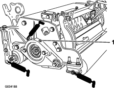
Lubricating the Cutting Unit
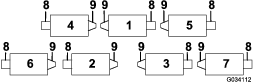
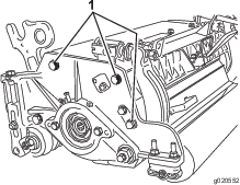
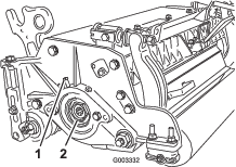
Each cutting unit has 6 grease fittings (Figure 28) that must be lubricated regularly with No. 2 lithium grease.
The lubrication points include the front roller (2), the rear roller (2), and the reel bearing (2).
-
Wipe each grease fitting with a clean rag.
-
Apply grease until clean grease comes out of the roller seals and the bearing relief valve.
-
Wipe any excess grease away.
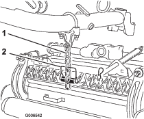
Adjusting the Reel Bearings
To ensure long life of the reel bearings, periodically check if reel end play exists. You can check and adjust the reel bearings as follows:
-
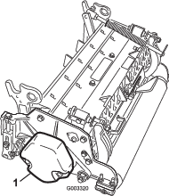
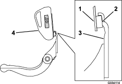
Loosen the reel-to-bedknife contact by turning the bedknife adjusting knobs (Figure 29) counterclockwise until no contact exists.
-
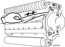
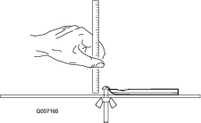
Using a rag or a thickly padded glove, hold on to the reel blade and try to move the reel assembly side to side (Figure 30).
-
If end play exists, proceeded as follows:
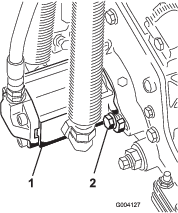
-
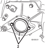
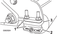
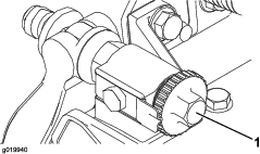
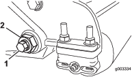
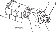
Loosen the external setscrew securing the bearing adjuster nut to bearing housing located on the left side of the cutting unit (Figure 31).
-
Using a 1-3/8 inch socket wrench, slowly tighten the reel-bearing adjustment nut until no end play of the reel exists. If adjusting the nut does not eliminate reel end play, replace the reel bearings.
Note: The reel bearings do not require preload. Overtightening the reel-bearing adjuster nut will damage the reel bearings.
-
-
Tighten the setscrew securing the bearing adjuster nut to the bearing housing.
Note: Torque the nut to 1.4 to 1.7 N∙m (12 to 15 in-lb).
Servicing the Bedknife
The bedknife service limits are listed in the following chart.
Important: Operating the cutting unit with the bedknife below the service limit may result in poor after-cut appearance and reduce the structural integrity of the bedknife for impacts.
| Bedknife Service Limit Chart | ||||
| Bedknife | Part | Bedknife Lip Height* | Service Limit* | Grind AnglesTop/Front Angles |
| EdgeMax® Low HOC (Optional) | 137-0832 | 5.6 mm(0.220 inch) | 6.4 to 12.7 mm(0.250 to 0.500 inch) | 10/5 degrees |
| Low HOC (Optional) | 110-4084 | 5.6 mm(0.220 inch) | 4.8 mm(0.190 inch) | 10/5 degrees |
| Extended EdgeMax® Low HOC (Optional) | 119-4280 | 5.6 mm(0.220 inch) | 4.8 mm(0.190 inch) | 10/10 degrees |
| Extended Low HOC (Optional) | 120-1640 | 5.6 mm(0.220 inch) | 4.8 mm(0.190 inch) | 10/10 degrees |
| EdgeMax® (Models 03698 and 03699) | 137-0833 | 6.9 mm(0.270 inch) | 4.8 mm(0.190 inch) | 10/5 degrees |
| Standard (Optional) | 108-9096 | 6.9 mm(0.270 inch) | 4.8 mm(0.190 inch) | 10/5 degrees |
| Heavy Duty (Optional) | 110-4074 | 9.3 mm(0.370 inch) | 4.8 mm(0.190 inch) | 10/5 degrees |
Note: All bedknife service limit measurements relate to the bottom of the bedknife (Figure 33).
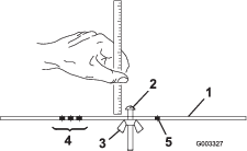
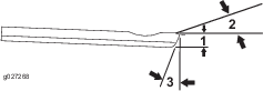
Checking the Top Grind Angle
The angle that you use to grind your bedknives is very important.
Use the angle indicator (Toro Part No. 131-6828) and the angle-indicator mount (Toro Part No. 131-6829) to check the angle that your grinder produces and then correct for any grinder inaccuracy.
-
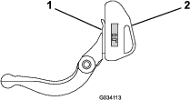
Place the angle indicator on the bottom side of the bedknife as shown in Figure 34.
-
Press the Alt Zero button on the angle indicator.
-
Place the angle-indicator mount on the edge of the bedknife so that the edge of the magnet is mated with the edge of the bedknife (Figure 35).
Note: The digital display should be visible from the same side during this step as it was in step 1.
-
Place the angle indicator on the mount as shown in Figure 35.
Note: This is the angle that your grinder produces; it should be within 2 degrees of the recommended top grind angle.
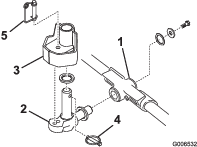
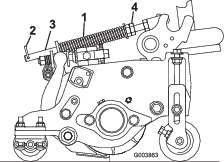
Servicing the Bedbar
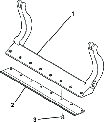
Removing the Bedbar
-
Turn the bedbar-adjusting screws counterclockwise to back the bedknife away from the reel (Figure 36).
-
Back out the spring-tension nut until the washer is no longer tensioned against the bedbar (Figure 36).
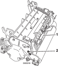
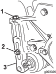
-
On each side of the machine, loosen the locknut securing the bedbar bolt (Figure 37).
-
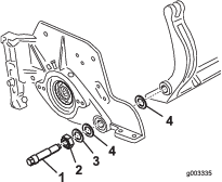
Remove each bedbar bolt, allowing the bedbar to be pulled downward and removed from the machine bolt (Figure 37). Account for 2 nylon washers and 1 stamped steel washer on each end of the bedbar (Figure 38).
Assembling the Bedbar
-
Install the bedbar, positioning the mounting ears between the washer and the bedbar adjuster.
-
Secure the bedbar to each side plate with the bedbar bolts (nuts on bolts) and 6 washers.
Note: Position a nylon washer on each side of side-plate boss. Place a steel washer outside each of the nylon washers (Figure 38).
-
Torque the bedbar bolts to 27 to 36 N∙m (240 to 320 in-lb).
Note: Tighten the locknuts until the outside steel washer stops rotating and end play is removed, but do not overtighten or deflect the side plates. The washers on the inside may have a gap.
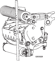
-
Tighten the spring-tension nut until the spring is collapsed, then back off 1/2 turn (Figure 39).
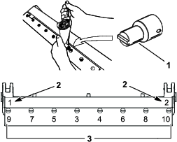
Installing the Bedknife
-
Remove the rust, scale, and corrosion from the bedbar surface and apply a thin layer of oil to the bedbar surface.
-
Clean the screw threads.
-
Apply anti-seize compound to the screws and install the bedknife to the bedbar as follows (Figure 40):
-
Grind the bedknife.
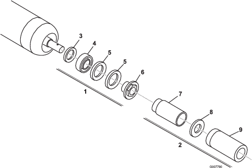
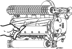
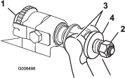
Servicing the Roller
The Roller Rebuild Kit (Part No. 114-5430) and the Roller Rebuild Tool Kit (Part No. 115-0803) (Figure 42) are available for servicing the roller. The Roller Rebuild Kit includes all the bearings, bearing nuts, inner seals, and outer seals to rebuild a roller. The Roller Rebuild Tool Kit includes all the tools and the installation instructions required to rebuild a roller with the roller rebuild kit. Refer to your parts catalog or contact your authorized Toro distributor for assistance.