Introduction

This machine is intended to be used by professional, hired operators in commercial applications. It is primarily designed for transporting, metering, and applying top-dressing materials. Using this product for purposes other than its intended use could prove dangerous to you and bystanders.

Read this information carefully to learn how to operate and maintain your product properly and to avoid injury and product damage. You are responsible for operating the product properly and safely.

Visit www.Toro.com for product safety and operation training materials, accessory information, help finding a dealer, or to register your product.

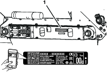
Whenever you need service, genuine Toro parts, or additional information, contact an Authorized Service Dealer or Toro Customer Service and have the model and serial numbers of your product ready. Figure 1 identifies the location of the model and serial numbers on the product. Write the numbers in the space provided.

Important: With your mobile device, you can scan the QR code (if equipped) on the serial number plate to access warranty, parts, and other product information.

g269187

This manual identifies potential hazards and has safety messages identified by the safety-alert symbol (Figure 2), which signals a hazard that may cause serious injury or death if you do not follow the recommended precautions.

g000502

This manual uses 2 words to highlight information. Important calls attention to special mechanical information and Note emphasizes general information worthy of special attention.

This product complies with all relevant European directives, for details please see the separate product specific Declaration of Conformity (DOC) sheet.

Warning

CALIFORNIA

Proposition 65 Warning

Use of this product may cause exposure to chemicals known to the State of California to cause cancer, birth defects, or other reproductive harm.

Safety

General Safety

This product is capable of amputating hands and feet and of throwing objects.

  • Read and understand the contents of both this Operator’s Manual and the operator’s manual of the Workman vehicle before using this machine. Ensure that everyone using this product knows how to use this machine and the Workman vehicle and understands the warnings.

  • Use your full attention while operating the machine. Do not engage in any activity that causes distractions; otherwise, injury or property damage may occur.

  • Do not put your hands or feet near moving components of the machine.

  • Do not operate the machine without all guards and other safety protective devices in place and functioning properly on the machine.

  • Keep bystanders and children out of the operating area. Never allow children to operate the machine.

  • Park the machine on a level surface; engage the parking brake; shut off the traction-unit engine; remove the key; and wait for all movement to stop before servicing or unclogging the machine. Allow the machine to cool before adjusting, servicing, cleaning, or storing it.

Improperly using or maintaining this machine can result in injury. To reduce the potential for injury, comply with these safety instructions and always pay attention to the safety-alert symbol Graphic, which means Caution, Warning, or Danger—personal safety instruction. Failure to comply with these instructions may result in personal injury or death.

Safety and Instructional Decals

Graphic

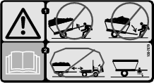
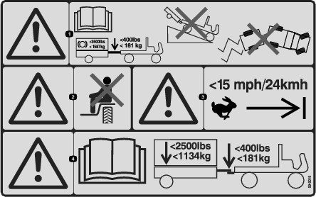
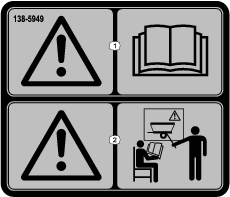
Safety decals and instructions are easily visible to the operator and are located near any area of potential danger. Replace any decal that is damaged or missing.

decal58-6520
decal100-7679
decal105-0708
decal99-0016
decal117-4979
decal132-1316
decal133-8061
decal138-5940
decal138-5941
decal138-5949

Setup

Installing the Tongue

Parts needed for this procedure:

Tongue assembly1
Lynch pin4
Clevis pin2
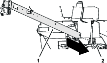
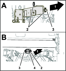
  1. Insert the tongue through the front receiver tube, the frame of the machine, and the rear receiver tube (Figure 3).

    g269253
  2. Align the holes in the tongue with the holes in the receiver tubes, and secure the tongue to the tubes with the 2 clevis pins and 4 lynch pins (Figure 4).

    g269254

Assembling the Hitch to the Traction-Unit Drawbar

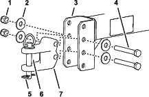
  1. Adjust the position of the hitch clevis to the tongue so that the tongue is level with the drawbar of the traction unit (Figure 5).

    g269296
  2. Assemble the hitch clevis to the tongue with the 2 capscrews, 4 washers, and 2 locknuts (Figure 5).

  3. Torque the capscrews and locknuts to 183 to 223 N∙m (135 to 165 ft lb).

  4. Secure the hitch to the drawbar with the hitch pin and hairpin (Figure 5).

Mounting the Optional Tongue Jack

Parts needed for this procedure:

Jack (optional)1

Assembling the Optional Jack to the Tongue

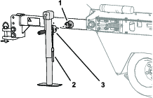
  1. Slide jack onto jack-mount tube of tongue (Figure 6).

    g280872
  2. Align holes in jack with holes in the mounting tube and secure the jack with the clevis pin (Figure 6).

Installing the Wire Harness

Parts needed for this procedure:

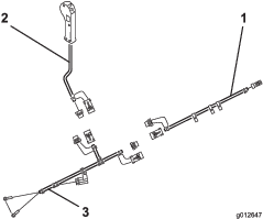
Wire harness assembly (topdresser harness, controller harness, and tow-vehicle harness)1
  1. Plug the connector of the topdresser wire harness into electrical connector on solenoid valve of the machine (Figure 7).

    g012647
  2. Route the ring terminals of the tow-vehicle harness to battery of the traction unit.

  3. Assemble the ring terminal for the black wire of the tow-vehicle harness to the negative battery cable.

  4. Assemble the ring terminal for the red wire to the positive battery cable.

  5. Unplug loop back connectors from each of the harnesses and plug the topdresser harness, controller harness, tow vehicle harness and together.

    Note: To prevent dirt or corrosion to harness connector pins, install the loop-back connectors into electrical connectors whenever vehicle harness is disconnected from the topdresser harness.

  6. Route topdresser harness along tongue and secure it to tongue with cable ties.

  7. Plug controller harness connector into topdresser wire harness connector.

  8. Route to controller harness to the operator's position in the traction unit and secure the harness along frame rail with cable ties.

Note: Wire harnesses have removable connectors that allow you to permanently assemble the tow vehicle harness to the traction unit and the topdresser harness to the machine.

Mounting the Skids

Parts needed for this procedure:

Skid4
Carriage bolt8
Flat washer8
Locknut8
  1. Position skid as shown in Figure 8.

    g012648
  2. Mount a skid to the mounting bracket with 2 carriage bolts, 2 flat washers and 2 locknuts.

  3. Repeat steps 1 and 2 for the skids at the 3 other mounting brackets.

Product Overview

Gate Metering Control

g266287

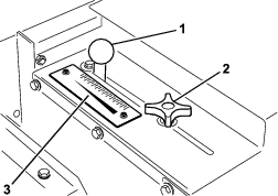
The gate-lock knob and adjusting handle are located at the left rear side of machine, and are used to adjust and lock the gate into the desired open height position (Figure 9).

  1. Loosen the adjusting gate-lock knob enough to allow gate and knob to slide freely in slot.

  2. Move the adjusting handle to set the gate into the desired position, and tighten the gate-lock knob secure the gate.

Hand Control Switch

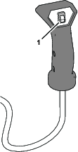
Press hand control switch to start or stop the flow of material from topdresser (Figure 10).

g269331
LengthWith the tongue254 cm (100 inches)
Without the tongue153.7 cm (60.5 inches)
Width 185 cm (73 inches)
Height 107.9 cm (42.5 inches)
Net weight 660 kg (1,455 lb)
Hopper volume 0.7 m³ (25 ft³)
Maximum material load 930 kg (2,050 lb)
Maximum tow speedEmpty24 kph (15 mph)
Fully loaded13 kph (8 mph)

Required Attachments

Topdresser Hydraulic Brake KitPart No. 106-9680

Optional Accessories

Tongue Jack (CE)Part No. 106-9699
Mobil EAL 224 H Biodegradable hydraulic fluid (5 US gallon container)Part No. 100-7674
Oil FilterPart No. 86-3010
Extra Vehicle HarnessPart No. 99-0198

Recommended Accessories

Hand Throttle KitModel No. 07420

Attachments/Accessories

A selection of Toro approved attachments and accessories is available for use with the machine to enhance and expand its capabilities. Contact your Authorized Service Dealer or authorized Toro distributor or go to www.Toro.com for a list of all approved attachments and accessories.

To ensure optimum performance and continued safety certification of the machine, use only genuine Toro replacement parts and accessories. Replacement parts and accessories made by other manufacturers could be dangerous, and such use could void the product warranty.

Operation

Before Operation

Before Operation Safety

  • The machine has different balance, weight, and handling characteristics compared to some other types of equipment. Read and understand the contents of this Operator's Manual before operating the machine. Become familiar with all controls and know how to stop quickly.

  • Never allow children or untrained people to operate or service the machine. Local regulations may restrict the age of the operator. The owner is responsible for training all operators and mechanics.

  • Become familiar with the safe operation of the equipment, operator controls, and safety signs.

  • Park the machine on a level surface; engage the parking brake; shut off the traction-unit engine; remove the key; and wait for all movement to stop before servicing or unclogging the machine. Allow the machine to cool before adjusting, servicing, cleaning, or storing it.

  • Know how to stop the machine and shut off the engine quickly.

  • Keep all shields and safety devices in place. If a shield, safety device, or decal is illegible or missing, repair or replace it before operating the machine.

  • Tighten any loose nuts, bolts, and screws to ensure that the machine is in safe operating condition. Ensure that the machine components are in place and secure.

  • Ensure that your vehicle is suitable for use with an implement of this weight by checking with your vehicle supplier or manufacturer.

  • Do not modify this equipment in any manner.

  • The tongue is the area on the machine where the hitch connects to the tow vehicle. The weight of the tongue affects the stability of the machine.

    • A negative or positive tongue weight can cause injury when connecting or disconnecting the machine to the tow vehicle. When installed, ensure that the optional jack stand is properly engaged.

    • When the weight of the tongue is forced up into the hitch of the tow vehicle, this produces a negative tongue weight.

    • When the weight of the tongue is forced down onto the hitch of the tow vehicle, this produces a positive tongue weight.

  • Never attach the machine to or remove the machine from the traction unit if there is material in the hopper. The tongue may flip up, causing injury.

Special Instructions for Workman and other Traction Units

Important: Use a traction unit with a hitch and brakes rated to 680 kg (1,500 lb).

Note: For improved traction and when towing the machine, add weight to the bed of the traction unit.

  • For operation over golf greens, most traction units equipped with flotation tires can tow the machine.

  • A 4WD traction unit is best for hilly or bermed approaches to greens.

  • Use trailer brakes when operating the machine on hilly terrain. A special trailer brake kit is available for the Workman vehicle. You can adapt this kit for other traction units with a 12 V brake light source.

Checking the Machine Before Operation

During Operation

During Operation Safety

  • The owner/operator can prevent and is responsible for accidents that may cause personal injury or property damage.

  • Wear appropriate clothing, including eye protection; long pants; substantial, slip-resistant footwear; and hearing protection. Tie back long hair and do not wear loose clothing or loose jewelry.

  • Do not operate the machine while ill, tired, or under the influence of alcohol or drugs.

  • Use your full attention while operating the machine. Do not engage in any activity that causes distractions; otherwise, injury or property damage may occur.

  • Keep your hands and feet out of the hopper.

  • Remain seated whenever the vehicle is in motion.

  • Using the machine demands attention. Failing to operate the vehicle safely may result in an accident, tip-over of the vehicle, and serious injury or death. Drive carefully, and to prevent tipping or loss of control, do the following:

    • Use extreme caution, reduce the speed, and maintain a safe distance around sand traps, ditches, water hazards, ramps, unfamiliar areas, or other hazards.

    • Reduce the speed of a loaded machine when negotiating terrain undulations to avoid causing the machine to become unstable.

    • Operate the machine only in good visibility to avoid holes or hidden hazards.

    • Look behind and down before backing up to be sure of a clear path.

    • Use care when approaching blind corners, shrubs, trees, or other objects that may obscure your vision.

    • Use caution when operating on a steep slope. Travel straight up and down slopes. Reduce speed when making sharp turns or when turning on hillsides. Avoid turning on hillsides whenever possible.

    • Use extra caution when operating on wet surfaces, at higher speeds or with a full load. Stopping time increases with a full load. Shift into a lower gear before starting up or down a hill.

    • Avoid sudden stops and starts. Do not go from reverse to forward or forward to reverse without coming to a complete stop.

    • Do not attempt sharp turns or abrupt maneuvers or other unsafe driving actions that may cause a loss of control.

    • Be aware of your surroundings when turning or backing up the machine. Ensure that the area is clear and keep all bystanders out of the operating area. Proceed slowly.

    • Slow down and use caution when making turns and crossing roads and sidewalks with the machine. Always yield the right-of-way.

    • Always watch out for and avoid low overhangs such as tree limbs, door jambs, overhead walkways, etc. Ensure that there is enough room over head to easily clear the vehicle and your head.

    • Operate the machine only in good visibility and appropriate weather conditions. Do not operate the machine when there is the risk of lightning.

    • If you are ever unsure about safe operation, stop working and ask your supervisor.

    • Do not leave the machine unattended while the tow vehicle is running.

  • Ensure that the machine is connected to the tow vehicle before loading.

  • Do not carry loads that exceed the load limits of the machine or the tow vehicle.

  • The stability of loads can vary—for example, high loads have a higher center of gravity. Reduce the maximum load limits to ensure better stability, if necessary.

  • To avoid causing the machine to tip over, do the following:

    • Carefully monitor the height and weight of the load. Higher and heavier loads can increase the risk of tipping.

    • Distribute the load evenly, from front to back and side to side.

    • Be careful when turning and avoid unsafe maneuvers.

    • Always ensure that the machine is connected to the vehicle before loading.

    • Do not put large or heavy objects into the hopper. This could damage the belt and rollers. Also ensure that the load has a uniform texture. The machine can unpredictably throw small rocks in the sand.

  • Before you leave the operator’s position, do the following:

    • Park the machine on a level surface.

    • Shut off the machine.

    • Engage the parking brake.

    • Shut off the engine and remove the key (if equipped).

    • Wait for all movement to stop.

  • Do not stand behind the machine when unloading.

  • Unload the topdresser or disconnect it from the vehicle only while on a level surface.

  • Ensure that the machine is connected to the tow vehicle before unloading.

  • Shut off the attachment when approaching people, vehicles, vehicle crossings, or pedestrian crossings.

  • When equipped, hydraulic trailer brakes may overheat the fluid in the hydraulic circuit if the brakes remain activated continuously. Always use a lower speed gear selection when descending long hills. Activate the brakes intermittently to allow for cooling cycles for both the vehicle and the topdresser.

Slope Safety

  • Review the vehicle specifications to ensure that you do not exceed its slope capabilities.

  • Slopes are a major factor related to loss of control and rollover accidents, which can result in severe injury or death. The operator is responsible for safe slope operation. Operating the machine on any slope requires extra caution.

  • The operator must evaluate the site conditions to determine if the slope is safe for machine operation including surveying the site. Always use common sense and good judgment when performing this survey.

  • The operator must review the slope instructions listed below for operating the machine on slopes. Consider the operating conditions on that day to determine whether to use the machine at the site. Changes in the terrain can result in a change in slope operation for the machine.

  • Avoid starting, stopping, or turning the machine on slopes. Avoid making sudden changes in speed or direction. Make turns slowly and gradually.

  • Do not operate a machine under any conditions where traction, steering, or stability is in question.

  • Remove or mark obstructions such as ditches, holes, ruts, bumps, rocks, or other hidden hazards. Tall grass can hide obstructions. Uneven terrain could overturn the machine.

  • Be aware that operating the machine on wet grass, across slopes, or downhill may cause the machine to lose traction. Loss of traction to the drive wheels may result in sliding and a loss of braking and steering.

  • Use extreme caution when operating the machine near drop offs, ditches, embankments, water hazards, or other hazards. The machine could suddenly roll over if a wheel goes over the edge or the edge caves in. Establish a safety area between the machine and any hazard.

Supporting the Machine with the Optional Jack

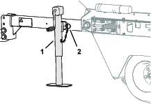
Use the jack when the you remove the machine from the traction unit.

  1. Remove the clevis pin.

  2. Rotate the jack vertical (Figure 11).

    g280875
  3. Secure the it to the mounting tube with the clevis pin (Figure 11).

  4. Extend the jack to support the machine.

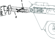
Stowing the Optional Jack

  1. Connect the machine to the tow vehicle.

  2. Fully raise the jack.

  3. Remove the clevis pin.

  4. Rotate the jack horizontal (Figure 12).

    g280874
  5. Secure the jack to the mounting tube with the clevis pin (Figure 12).

Operating the Machine

Important: Always read and understand the operator's manual for the traction unit before using the machine.

  1. Start the traction unit; refer to the traction unit operator’s manual.

  2. Before adding material into hopper, drive the traction unit and topdresser to check that the belt moves smoothly.

    Note: When operating the machine in cold weather; refer to Preparing for Cold Weather Operation.

  3. Load sand or other topdressing material into the hopper; refer to Loading the Hopper.

    Important: Overloading the hopper may result in tire side-wall deflection and marking the green on first few passes. Check the air pressure of all tires; refer to Checking the Tire Air Pressure

  4. Transport the machine to the area to be top-dressed.

  5. Adjust the metering gate to the desired application rate, and lock the gate into position with the gate-lock knob.

    When applying sand, refer to the Sand Application Rate for additional information.

  6. For best results, shift traction unit to the LOW range position. Drive the traction unit forward at the desired ground speed.

  7. Press hand control switch to start or stop the flow of material from topdresser.

Loading the Hopper

  • The maximum material volume of the hopper is 0.7 m³ (25 ft³).

  • Generally, dry sand weighs 1602 kg/m³ (100 lb/ft³) and wet sand weighs 1922 to 2082 kg/m³ (120 to 130 lb/ft³). You will overload the machine if you load more than 930 kg (2,050 lb) of sand into the hopper.

  • Position the weight of the load evenly from front to rear and evenly from side to side.

  • Transporting or topdressing with a full load can cause shifting of the sand. This shifting happens most often while turning, going up or down hills, suddenly changing speeds or while driving over rough surfaces. Shifting loads can lead to tip-overs. Use caution when transporting or topdressing with a full load.

  • Heavy loads increase stopping distance and reduce your ability to turn quickly without tipping over.

Sand Application Rate

The rate of sand applied depends on the gate setting. Sand varies in moisture and coarseness (size of grain), which effects the application rate. These factors must be taken into consideration when deciding the amount of sand required for the application. Test a small area to decide the correct amount. To increase application rate open gate to a higher scale mark.

The machine is ground driven which assures consistent application, from green to green, when towing the machine at 3.2 to 13 kph (2 to 8 mph).

Sand Precautions

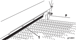
The machine is equipped with a flexible gate edge (Figure 13) and a spring release mechanism to reduce the chance of sand chunks or rocks getting lodged during operation. To ensure long belt life, sift or check the sand for rocks with sharp edges that may damage conveyor belt.

g012651

Preparing for Cold Weather Operation

Although limited by the traction of the drive tires, you may use the machine in cold weather. With certain limitations, you may use the machine to apply a salt/sand mixture on pavement for ice control. The PVC conveyor belt material becomes very stiff in cold weather and requires more power to operate belt. The life of the belt is reduced by approximately 50% when operated below temperatures of 40°F. (5°C).

Important: Do not operate the topdresser during temperatures of -7°C (20°F) or lower.

  1. Increase the conveyer belt tension by adjusting spring compression to 101 mm (4 inches); refer to Tensioning the Conveyor Belt.

  2. Run belt before loading the hopper with material to assure that belt system moves freely.

    Important: If belt/drive roller slip, damage to belt or roller may occur.

Important: Before operating the machine during warm weather, adjust the belt tension to 112 mm (4-7/16 inches) spring compression.

Operating Tips

  • The topdresser material application system is ground driven, so you need to tow the machine to check the operation of the belt and brush.

  • Top dressing works best when towing the machine 3.2 to 13 kph (2 to 8 mph). The machine compensates for variations in travel speed, and will give consistent distribution, even if your travel speed changes during a pass across the green. The operator/superintendent should make the gate setting selection (variable in 1/8 increments to 13) and make a first pass to determine if application rate is acceptable.

    When applying sand, refer to the Sand Application Rate for additional information.

  • After the machine is moving, operation begins when the hand control switch is activated. It may require practice to start and stop the flow of material at the desired area of a green or tee box.

  • Before loading hopper, make sure that the topdresser is properly connected to tow vehicle, to prevent flip-up or any unintended tongue movement. Do not disconnect the topdresser from tow vehicle while material is in the hopper. The tongue may flip up causing injury.

  • The topdresser is wider than most traction units. Before traveling through a narrow area such as a gate, door entry, etc., check width of the opening before proceeding, and allow clearance to turn the machine.

  • The top dresser adds extra towing weight to the traction unit. Drive it safely.

    • Do not drive on the highway or a public road.

    • Always slow the traction unit when approaching and while making a turn.

    • Always slow the traction unit when driving in an unfamiliar area or over rough terrain.

    • Always slow the traction unit when changing direction of travel or when preparing to stop.

    • When turning or driving the machine on a slope, always slow the traction unit, then turn the machine to prevent losing control and possible rollover.

    • Do not make sudden or sharp turns. Do not suddenly change direction of travel on an incline, ramp, grade, slope, or similar surface.

    • Always adjust the traction unit speed to allow for existing ground conditions such as wet or slick surfaces, loose sand or gravel, low-visibility conditions such as dim or bright lighting, fog, mist, or rain.

    • Be especially careful when driving a heavily loaded vehicle down an incline or slope. Drive the vehicle up and down the face of the slopes, inclines, or grades whenever possible. Do not drive across the face of a slope if possible. There is a risk of overturning the machine, which can result in serious injury or death.

    Warning

    Tipping or rolling the tow vehicle on a hill will cause serious injury.

    • If engine stalls or you lose headway on a hill, never attempt to turn tow vehicle around.

    • Always back straight down a hill in reverse gear.

    • Do not back down a hill with the transmission in neutral or with the clutch engaged, using only the brakes.

    • Do not add sideboards or panels to the top of the hopper to increase the load capacity. The additional weight will cause tipping or rolling of the tow vehicle and lead to serious injury.

    • Do not drive across a hill, always drive straight up or down. Avoid turning on a hill. Do not "drop the clutch" or slam on the brakes. Sudden speed change can initiate a tip-over.

  • In tight areas, where a straight line pass across a green is not possible, you can back the machine into the area without harm and begin topdressing when pulling forward.

  • Before backing up, look to the rear and assure that no one is behind. Back up slowly and watch the machine closely.

  • Use extreme caution and slow speed when backing up the machine and traction unit.

  • The maximum recommended towing speed of the machine is 24 kph (15 mph) when empty and 13 kph (8 mph) when loaded. As with any trailer, always use caution when turning or backing up. Be aware of persons or objects near the topdresser path of travel.

  • Watch out for traffic when near or crossing roads. Always yield the right of way to pedestrians and other vehicles.

  • If the top dresser begins to vibrate abnormally, stop the traction unit, engage the parking brake, shut off engine, remove the key, and wait for all moving parts to stop. Repair any wear or damage before towing the machine.

  • If you hear cavitation noise while transporting the machine across the golf course, slow down, return to maintenance, and investigate the cause. Do not exceed the 13 kph (8 mph) tow speed. This machine was not designed for travel on highways. Towing the machine faster than 24 kph (15 mph) will damage the internal hydraulic components.

  • Before servicing or making any adjustments to the top dresser:

    • Stop the traction unit and set the parking brake.

    • Shut off the engine, remove key, and wait for all moving parts to stop before leaving the operator’s seat.

  • Keep all hardware tight secure. Install all serviceable parts removed during maintenance or adjustments.

  • When loading the top-dressing material into the hopper, be careful that the loader or skid steer bucket does not strike and damage the hopper. Although the hopper is designed wide enough to clear most buckets, it is not strong enough to take a contact and may deform the sheet metal.

  • Material application is always best with dry material, but wet sand can be spread with the machine. You may need to adjust the gate setting, but the material should flow out and spread relatively smooth and consistent. If the belt slips, check the belt tension and clean-out provisions.

  • Top-dressing material can vary in grain size as well as moisture content. It can also contain impurities that may either damage greens mowers or plant tissue. Always control the source of top-dressing material, and use care when handling and loading it.

  • A sight window is provided at the right front hopper panel to monitor remaining material while topdressing. It is a good practice to check the sight window and for hopper volume before beginning application to assure that you do not run out of top-dressing material in the middle of the pass.

  • The special oscillating drive axles on the machine are designed to continuously power the hydraulic system while the machine travels over surface irregularities of a green or tee. Always approach a severe berm slowly to avoid sudden impact of the axles with the turf, and to reduce the potential of leaving tire marks on the approach to the green.

    Warning

    Rotating parts of the machine can grab or pinch you.

    Stay clear of brush and conveyor belt while unit is running.

  • Safe operation begins before taking the top dresser out for a day's work. Read and understand the operating instructions in the Toro Workman or other traction unit operator's manual before using the topdresser.

After Operation

After Operation Safety

  • Park the machine on a level surface; engage the parking brake; shut off the traction-unit engine; remove the key; and wait for all movement to stop before servicing or unclogging the machine. Allow the machine to cool before adjusting, servicing, cleaning, or storing it.

  • Avoid soft ground because the jack leg could sink and cause the machine to tip over.

  • Shut off the machine whenever you are transporting or not using it.

  • Keep all parts of the machine in good working condition and all hardware tightened.

  • Replace all worn, damaged, or missing decals.

Maintenance

Note: Determine the left and right sides of the machine from the normal operating position.

Maintenance Safety

  • Before you leave the operator’s position, do the following:

    • Park the machine on a level surface.

    • Shut off the machine.

    • Engage the parking brake.

    • Shut off the engine and remove the key (if equipped).

    • Wait for all movement to stop.

  • Allow machine components to cool before performing maintenance.

  • Perform only those maintenance instructions described in this manual. If major repairs are ever needed or assistance is desired, contact an authorized Toro distributor.

  • If possible, do not perform maintenance while the engine is running. Keep away from moving parts.

  • Do not check or adjust the chain tension when the vehicle engine is running.

  • Carefully release pressure from components with stored energy.

  • Support the machine with jack stands whenever you work under the machine.

  • After maintaining or adjusting the machine, ensure that all guards are installed.

  • Keep all parts of the machine in good working condition and all hardware tightened.

  • Replace all worn or damaged decals.

  • To ensure safe, optimal performance of the machine, use only genuine Toro replacement parts. Replacement parts made by other manufacturers could be dangerous, and such use could void the product warranty.

Recommended Maintenance Schedule(s)

Maintenance Service IntervalMaintenance Procedure
After the first hour
  • Torque the wheel bolts.
  • After the first 10 hours
  • Torque the wheel bolts.
  • Before each use or daily
  • Check the tire air pressure.
  • Check the hydraulic lines and hoses
  • Check the hydraulic fluid level.
  • Every 40 hours
  • Check the brush position and wear.
  • Every 200 hours
  • Lubricate all the grease fittings.
  • Torque the wheel bolts.
  • Every 800 hours
  • If you are not using the recommended hydraulic fluid or have ever filled the reservoir with an alternative fluid, replace the hydraulic filter.
  • If you are not using the recommended hydraulic fluid or have ever filled the reservoir with an alternative fluid, change the hydraulic fluid.
  • Every 1,000 hours
  • If you are using the recommended hydraulic fluid, replace the hydraulic filter.
  • Every 2,000 hours
  • If you are using the recommended hydraulic fluid, change the hydraulic fluid.
  • Pre-Maintenance Procedures

    Preparing for Maintenance

    1. Shut off the hand-control switch for the topdresser.

    2. Move the machine to a level surface.

    3. Set the parking brake of the traction unit, shut off the engine, remove the key, and wait for all moving parts to stop before leaving the operator’s seat.

    Raising the Machine

    1. Empty the hopper.

    2. Perform the steps in Preparing for Maintenance.

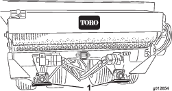
    3. Use the skids as the jacking points.

      g012654
    4. Support the machine with jack stands.

    5. When working on the wheels, pivot them up or down to expose wheel bolts.

      Important: If you remove the wheels and installed them, torque wheel bolts as specified in Torquing the Wheel Bolts. Incorrect bolt torque could result in failure or loss of the wheel.

    Lubrication

    Grease Specification

    No. 2 lithium grease

    Greasing the Bearings and Bushings

    Maintenance Service IntervalMaintenance Procedure
    Every 200 hours
  • Lubricate all the grease fittings.
    1. Perform the steps in Preparing for Maintenance.

    2. Lubricant each of the grease fitting described in the grease-fitting table with the specified grease.

    Grease-Fitting Table

    LocationQuantity
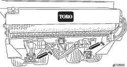
    Roller shaft bearing (Figure 15)4
    Brush shaft bearing (Figure 15)1
    Pivot bearing (Figure 164
    Wheel bearing (Figure 16)4

    Important: Lubricate the bearings to maintain a slight leakage between bearings and housings. Too much grease can cause overheating or damage to seals.
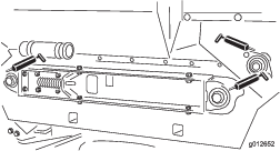
    g012652
    g012653

    Note: Do not lubricate the drive chains unless they become stiff from rust. If the chain rusts, lightly lubricate it with a dry-type lubricant. This reduces the likelihood of sand build-up or other top-dressing material adhering to the chain.

    Drive System Maintenance

    Checking the Tire Air Pressure

    Maintenance Service IntervalMaintenance Procedure
    Before each use or daily
  • Check the tire air pressure.
    1. Perform the steps in Preparing for Maintenance.

    2. Check the tire air pressure.

      You should measure 138 to 207 kPa (20 to 30 psi) air pressure.

    3. If the tire air pressure is too low or too high, add air to or remove air from the tires until you measure 138 to 207 kPa (20 to 30 psi).

    Torquing the Wheel Bolts

    Maintenance Service IntervalMaintenance Procedure
    After the first hour
  • Torque the wheel bolts.
  • After the first 10 hours
  • Torque the wheel bolts.
  • Every 200 hours
  • Torque the wheel bolts.
  • Important: Failure to maintain proper torque could result in failure or loss of wheel.

    1. Perform the steps in Preparing for Maintenance.

    2. Torque 20 wheel bolts to 109 to 122 N∙m(80-90 ft-lb).

    Tensioning the Wheel-Drive Chain

    1. Perform the steps in Preparing for Maintenance.

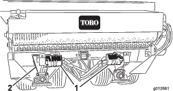
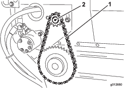
    2. Loosen carriage bolts and nuts that secure the hydraulic motor/pump to axle cradle (Figure 17).
      g012661
    3. Rotate motor sprocket assembly (Figure 17) until the wheel-drive chain deflects 3.2 mm (1/8 inch).

      Note: Access to chain is through cutout in lower side of axle cradle.

      Important: Do not overtension the chain or it will wear prematurely. Do not under-tension the chain or it will cause sprocket wear.
    4. Tighten mounting bolts.

    Tensioning the Conveyor-Belt Chain

    1. Perform the steps in Preparing for Maintenance.

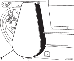
    2. Remove the chain cover (Figure 18).

      g012659
    3. Loosen bolts and nuts that secure the motor and sprocket assembly to the main frame (Figure 19).

    4. Rotate motor and sprocket assembly (Figure 19) in mounting slots until the conveyer-belt chain deflects 3.2 mm (1/8 inch).

      Important: Do not overtension the chain or it will wear prematurely. Do not under-tension the chain or it will cause sprocket wear.

      g012660
    5. Tighten mounting bolts (Figure 19).

    6. Install chain cover (Figure 18).

    Belt Maintenance

    Tensioning the Conveyor Belt

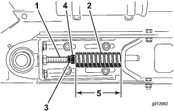
    When conveyor belt is adjusted properly, the compressed length of each compression spring should be 112 mm (4-7/16 inches). Adjust conveyor belt as follows:

    1. Empty the hopper.

    2. Perform the steps in Preparing for Maintenance.

    3. Loosen rear jam nut (Figure 20).

      g012662
    4. Adjust forward jam nut to compression spring to 112 mm (4-7/16 inches).

    5. Tighten jam rear nut.

    6. Repeat steps 3 through 5 at the other side of the machine.

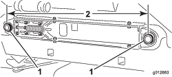
    7. Measure the distance between center points of the belt-roller shafts at each side of machine to ensure that the measurements are equal (Figure 21).

      Equal distance measures approximately 895 mm (35-1/4 inches).
      g012663

    Replacing the Conveyor Belt

    Preparing to Machine

    1. Empty the hopper.

    2. Perform the steps in Preparing for Maintenance.

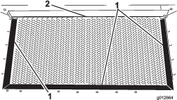
    3. Inspect hopper seals and gate edge for wear or torn edges (Figure 22).

      Replace worn or damaged components to ensure proper operation of new conveyor belt.
      g012664

    Removing the Conveyer Chain

    1. Remove chain cover (Figure 23).

      g012659
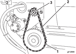
    2. Remove master link from chain and remove chain from small sprocket (Figure 24).

      If needed, loosen the motor-mount bolts to remove the master link.

      g012666

    Disassembling the Slider Bed

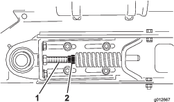
    1. Loosen forward and rear jam nuts on tension rod to release spring tension (Figure 25).
      g012667
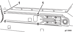
    2. At each side of machine, remove 2 capscrews, 2 washers, and 2 locknuts that secure the hopper to slider-frame rails (Figure 26).
      g012668
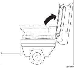
    3. Pivot hopper rearward and lean it against wall, post, ladder, etc. (Figure 27).

      Important: Do not allow hopper to rest against the rear of machine to avoid damaging the brush or the hydraulic couplers.Make sure that the hopper is pivoted beyond center and/or secured to wall or post to prevent it from accidentally falling on work area (Figure 27).
      g012669
    4. At the right side of machine, loosen 2 capscrews that secure slider-frame rail to the right fender (Figure 28). Ensure that the capscrews are loose enough to allow slider bed tip.
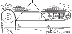
      g012670
    5. At the left side of machine, remove 2 capscrews and 2 washers that secure slider-frame rail to the left fender (Figure 29).
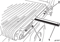
      g012671

    Removing the Belt

    Cut belt and remove it from rollers.

    Installing the Belt

    1. Insert a lift bar though the hole at the left slider-frame rail, and raise the lift bar to tip frame rail slightly; refer to Figure 29 in Disassembling the Slider Bed.

    2. Assemble the belt over the lift bar and rollers as far as possible.

    3. Insert a plastic belt tool between each roller and the belt.

      Rotate rollers until each tool is positioned to the outside of each roller. Insert the tool past rib in the center of belt.

    4. Slide belt and belt tools further onto rollers until belt is centered on rollers.

    5. Remove belt tools.

    6. Align belt so that the belt rib fits into alignment grooves in each roller.

    Assembling the Slider Bed

    1. At the left side of machine, assemble the slider-frame rail to the left fender (Figure 30) with the 2 capscrews and 2 washers that you removed in Disassembling the Slider Bed, and tighten the capscrews.

      g012671
    2. At the right side of machine, tighten 2 capscrews that secure slider-frame rail to the right fender (Figure 31).

      g012670
    3. Carefully rotate the hopper down onto the slider-frame rails; refer to Figure 27 of Disassembling the Slider Bed.

    4. At each side of machine, secure the hopper to slider-frame rails (Figure 32) with the 2 capscrews, 2 washers, and 2 locknuts that you removed in Disassembling the Slider Bed.

      g012668
    5. Tension the conveyer belt; refer to Tensioning the Conveyor Belt.

    Installing the Conveyer Chain

    1. Assemble the chain onto the small sprocket and secure the chain with the master link (Figure 33).
      g012666
    2. If you loosen the motor-mount bolts, tension the conveyer-belt chain, refer to Tensioning the Conveyor-Belt Chain.

    3. Install the chain cover (Figure 34).

      g012659

    Hydraulic System Maintenance

    Hydraulic System Safety

    • Seek immediate medical attention if fluid is injected into skin. Injected fluid must be surgically removed within a few hours by a doctor.

    • Ensure that all hydraulic-fluid hoses and lines are in good condition and all hydraulic connections and fittings are tight before applying pressure to the hydraulic system.

    • Keep your body and hands away from pinhole leaks or nozzles that eject high-pressure hydraulic fluid.

    • Use cardboard or paper to find hydraulic leaks.

    • Safely relieve all pressure in the hydraulic system before performing any work on the hydraulic system.

    Checking the Hydraulic Lines and Hoses

    Maintenance Service IntervalMaintenance Procedure
    Before each use or daily
  • Check the hydraulic lines and hoses
  • Inspect hydraulic lines and hoses daily for leaks, kinked lines, loose mounting supports, wear, loose fittings, weather deterioration and chemical deterioration. Make all necessary repairs before operating the machine.

    Hydraulic Fluid Specifications

    The reservoir is filled at the factory with high-quality hydraulic fluid. Check the level of the hydraulic fluid before you first start the engine and daily thereafter; refer to Checking the Hydraulic Fluid Level.

    Recommended hydraulic fluid: Toro PX Extended Life Hydraulic Fluid; available in 19 L (5 US gallon) pails or 208 L (55 US gallon) drums.

    Note: A machine using the recommended replacement fluid requires less frequent fluid and filter changes.

    Alternative hydraulic fluids: If Toro PX Extended Life Hydraulic Fluid is not available, you may use another conventional, petroleum-based hydraulic fluid having specifications that fall within the listed range for all the following material properties and that it meets industry standards. Do not use synthetic fluid. Consult with your lubricant distributor to identify a satisfactory product.

    Note: Toro does not assume responsibility for damage caused by improper substitutions, so use products only from reputable manufacturers who will stand behind their recommendation.

    High Viscosity Index/Low Pour Point Anti-wear Hydraulic Fluid, ISO VG 46

    Material Properties: 
     Viscosity, ASTM D445cSt @ 40°C (104°F) 44 to 48
     Viscosity Index ASTM D2270140 or higher
     Pour Point, ASTM D97-37°C to -45°C (-34°F to -49°F)
     Industry Specifications:Eaton Vickers 694 (I-286-S, M-2950-S/35VQ25 or M-2952-S)

    Note: Many hydraulic fluids are almost colorless, making it difficult to spot leaks. A red dye additive for the hydraulic fluid is available in 20 ml (0.67 fl oz) bottles. A bottle is sufficient for 15 to 22 L (4 to 6 US gallons) of hydraulic fluid. Order Part No. 44-2500 from your authorized Toro distributor.

    Important: Toro Premium Synthetic Biodegradable Hydraulic Fluid is the only synthetic biodegradable fluid approved by Toro. This fluid is compatible with the elastomers used in Toro hydraulic systems and is suitable for a wide-range of temperature conditions. This fluid is compatible with conventional mineral oils, but for maximum biodegradability and performance, the hydraulic system should be thoroughly flushed of conventional fluid. The oil is available in 19 L (5 US gallon) pails or 208 L (55 US gallon) drums from your authorized Toro distributor.

    Checking the Hydraulic Fluid Level

    Maintenance Service IntervalMaintenance Procedure
    Before each use or daily
  • Check the hydraulic fluid level.
    1. Perform the steps in Preparing for Maintenance.

    2. Clean area around filler neck and cap of hydraulic reservoir, and remove the cap (Figure 35).

      g280776
    3. Check the hydraulic-fluid level.

      The fluid level should be 1/2 way up the screen in filler neck (Figure 35).

    4. If level is low, add the specified hydraulic fluid to raise level.

    5. Install the hydraulic-reservoir cap (Figure 35).

    Replacing the Hydraulic Filter

    Maintenance Service IntervalMaintenance Procedure
    Every 800 hours
  • If you are not using the recommended hydraulic fluid or have ever filled the reservoir with an alternative fluid, replace the hydraulic filter.
  • Every 1,000 hours
  • If you are using the recommended hydraulic fluid, replace the hydraulic filter.
    1. Perform the steps in Preparing for Maintenance.

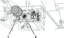
    2. Clean area around filter and hydraulic manifold, align a drain pan under filter, and remove filter (Figure 36).
      g280778
    3. Lubricate the gasket of the new filter with the specified hydraulic fluid; refer to Hydraulic Fluid Specifications.

    4. Clean the filter-mounting area of the hydraulic manifold (Figure 36).

    5. Thread the filter onto the filter mount until gasket manifold, then tighten filter one-half turn.

    6. Tow machine to power the hydraulic system and check for hydraulic leaks.

    Changing the Hydraulic Fluid

    Maintenance Service IntervalMaintenance Procedure
    Every 800 hours
  • If you are not using the recommended hydraulic fluid or have ever filled the reservoir with an alternative fluid, change the hydraulic fluid.
  • Every 2,000 hours
  • If you are using the recommended hydraulic fluid, change the hydraulic fluid.
  • Hydraulic reservoir fluid capacity: approximately 9.5 L (2.5 US gallon)

    Important: If fluid becomes contaminated, contact your authorized Toro distributor because you must drain the complete hydraulic system. Contaminated fluid looks milky or black when compared to clean oil.

    1. Perform the steps in Preparing for Maintenance.

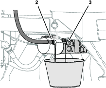
    2. Align a drain pan with a 9.5 L (2.5 US gallon) capacity under the hydraulic manifold (Figure 37).
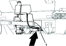
      g280774g280775
    3. Remove the return hose from the fitting in the hydraulic manifold and allow the hydraulic fluid to drain completely (Figure 37).

    4. Install and tighten return hose (Figure 37).

    5. Clean area around filler neck and cap of hydraulic reservoir, and remove the cap; refer to Figure 35 in Checking the Hydraulic Fluid Level.

    6. Add approximately 9.5 L (2.5 US gallon) of the specified hydraulic fluid; refer to Hydraulic Fluid Specifications.

      Important: Use only hydraulic fluids specified. Other fluids could cause damage to components of the hydraulic system.

    7. Check level of fluid and add enough to the fluid level stated in Checking the Hydraulic Fluid Level.

      Important: Do not overfill the reservoir with hydraulic fluid.

    8. Install hydraulic-reservoir cap; refer to Figure 35 in Checking the Hydraulic Fluid Level.

    Brush Maintenance

    Checking the Brush for Position and Wear

    Maintenance Service IntervalMaintenance Procedure
    Every 40 hours
  • Check the brush position and wear.
  • Brush must make enough contact with conveyor belt to disperse top-dressing material but not restrict the rotation of the brush. A piece of stiff paper can be inserted between the conveyor belt and the brush to check the adjustment.

    1. Insert a piece of stiff between the conveyor belt and the brush to check the adjustment.

    2. Check that the brush is same height from side to side.

    3. Check the condition of the brush bristles.

      If the bristles are excessively worn replace the brush. If the bristles are worn uneven either replace the brush or adjust the brush position; refer to Adjusting the Brush Position.

    Adjusting the Brush Position

    Note: If you are using moist top-dressing material, you may need to adjust the brush position so that the bristles will whisk material from between conveyor belt lugs without excessively contacting smooth portion of belt.

    1. Loosen nuts that secure the bearing housing (Figure 38) to right side of machine.
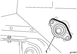
      g012657
    2. Loosen nuts that secure the brush motor (Figure 39) to left side of machine.
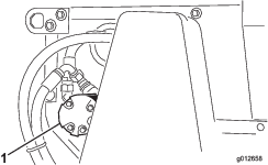
      g012658
    3. Slide brush into position at right side, and snug the nuts.

    4. Slide brush into position at left side, and snug the nuts.

    5. Insert a piece of stiff paper between the brush and the conveyor belt.

      The brush must be the same height from side to side.

    6. If the brush position is correct, tighten nuts.

      If the brush position is not correct, repeat steps 1 through 6.

    Cleaning

    Washing the Machine

    • Thoroughly clean the machine, especially inside the hopper. Clean the hopper and conveyor belt area free of any sand particles.

    • Wash the machine as needed using water alone or with a mild detergent. You may use a rag when washing the machine.

    Important: Do not use brackish or reclaimed water to clean the machine.

    Important: Do not use power-washing equipment to wash the machine. Power-washing equipment may damage the electrical system, loosen important decals, or wash away necessary grease at friction points. Avoid excessive use of water at the wiring and hydraulic manifold.
    Storage

    Storage Safety

    • Shut off the machine, remove the key (if equipped), and wait for all movement to stop before you leave the operator’s position. Allow the machine to cool before adjusting, servicing, cleaning, or storing it.

    • Do not store the machine or fuel container where there is an open flame, spark, or pilot light, such as on a water heater or other appliance.

    Preparing the Machine for Storage

    • Park the machine on a hard, level surface; engage the parking brake; shut off the engine; remove the key; and wait for all movement to stop before leaving the machine.

    • When the optional jack is installed, rotate it from the horizontal (traveling) position, to the vertical position.

    • Thoroughly clean the topdresser, especially inside the hopper. The hopper and conveyor belt area should be free of any remaining sand particles.

    • Tighten all fasteners.

    • Lubricate all grease fittings and bearings. Wipe off excess lubricant.

    • The unit should be stored out of the sun to prolong the life of the conveyor belt. When stored outside it is recommended to cover the hopper with a trap.

    • Check the tension of the drive chain. Adjust the tension, if necessary.

    • Check the tension of the conveyor belt. Adjust the tension, if necessary.

    • When bringing topdresser out of storage, check for smooth operation of belt before adding material in hopper.

    Troubleshooting

    ProblemPossible CauseCorrective Action
    The control wires are difficult to connect or disconnect.
    1. The traction unit has the wrong connector.
    2. The on/off connections are switched with brake wiring.
    1. Purchase an additional harness from your authorized Toro distributor.
    2. Correct the connections.
    The topdresser is hard to pull with the traction unit.
    1. The wheel motors/pumps are not turning.
    2. The brake solenoid is activated.
    3. The hydraulic oil is hot.
    1. The hydraulic plumbing is reversed.
    2. Check the wiring.
    3. Correct the condition.
    The machine leaks hydraulic fluid.
    1. The fittings are loose.
    2. The oil filter is loose.
    3. A fitting is missing an O-ring.
    4. The hydraulic reservoir overfilled with fluid.
    1. Tighten the fittings.
    2. Tighten the oil filter.
    3. Install the missing O-ring.
    4. Remove some hydraulic fluid from the reservoir.
    The conveyer belt and/or brush does not function.
    1. The solenoid wiring is not providing 12 V.
    2. The hand control switch is worn or damaged.
    3. The hydraulic motors/pumps are not turning.
    4. The conveyer belt slips.
    1. Check the fuse and electrical connections.
    2. Check for continuity through the switch and check diode in electrical solenoid connector.
    3. Check the wheel-drive chain.
    4. Check the conveyer belt tension.
    The conveyer belt is misaligned or moves off track.
    1. The rollers do not have equal center distance.
    2. The belt tension is incorrect.
    3. The bearing lock collars securing roller are not tight.
    4. The belt rib is not aligned the groove in rollers.
    1. Adjust the side-to-side distance.
    2. Make sure that the springs are compressed equally at each side of the machine.
    3. Tighten the bearing lock collars.
    4. Align the belt rib with the groove in rollers.

    Schematics

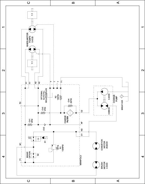
    Hydraulic Schematic 138-5972

    g280721

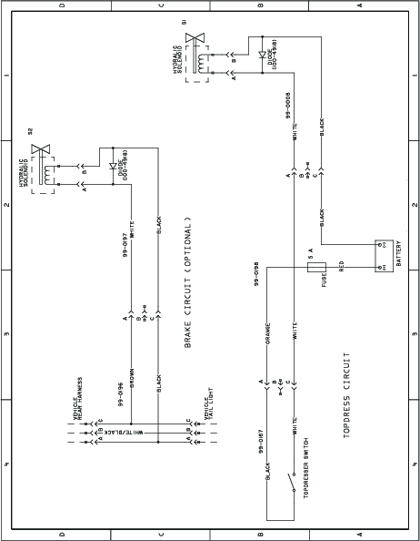
    Electrical Schematic 100-7687

    g269551