Installation
Preparing a Machine
-
Park a machine on a level surface.
-
Engage the parking brake.
-
Shut off the engine and remove the key.
-
For Electric GTX Models: disconnect the main negative battery cable (black) that connects the bank of batteries to the ground point of the machine; refer to your Operator’s Manual.
-
For all other Workman Models: disconnect the negative battery cable; refer to your Operator’s Manual.
Replacing a Front Light
Parts needed for this procedure:
| Light | 1 |
| Bracket | 1 |
-
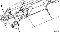
Remove the 2 existing screws from the headlight bracket (Figure 1).
Retain the fasteners.
-
Remove the existing front position/signal light.
-
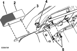
Install the new front position/signal light to the bracket using the previously removed 2 screws (Figure 2).
Note: Ensure that the clear lens (position light) is positioned to the inside and the amber lens (signal light) is positioned to the outside (Figure 2).
-
Connect the wire harness lead to the front position/signal light.
Replacing a Front Light
Parts needed for this procedure:
| Light | 1 |
| Bracket | 1 |
-
Remove the existing front position/signal light.
Retain the fasteners.
-
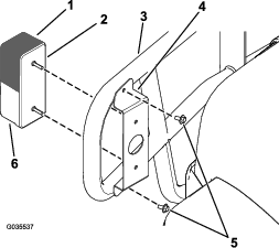
Install the front position/signal light to the brush guard using the front bracket and the previously removed 2 self-tapping screws (1/4 x 1/2 inch) as shown in Figure 3.
Important: Torque the 4 self-tapping screws (1/4 x 1/2 inch) to 452 to 508 N∙cm (40 to 45 in-lb).
Note: Ensure that the amber lens (signal light) is positioned on top of the clear lens (position light) as shown in Figure 3.
-
Connect the wire harness lead to the front position/signal light.
Replacing a Front Light
Parts needed for this procedure:
| Light | 1 |
| Bracket | 1 |
-
Remove the existing front position/signal light.
Retain the fasteners.
-
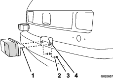
Secure the light to the bracket using the previously removed fasteners (Figure 4).
Note: Ensure that the clear lens (position light) is positioned to the inside and the amber lens (signal light) is positioned to the outside (Figure 4).
Note: The brackets are distinguishable by the angle of the face plate and a longer standing leg that faces outboard (Figure 4).
-
Connect the wire harness lead to the front position/signal light.
Replacing a Front Light
Parts needed for this procedure:
| Light | 1 |
| Left bracket | 1 |
| Right bracket | 1 |
-
Remove the existing front position/signal light.
Retain the fasteners.
-
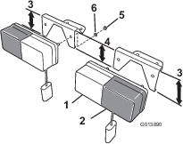
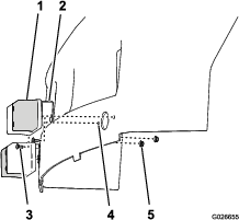
Push the bracket on to the studs of the light (Figure 5).
Important: Ensure that you install the bracket to the light so that the angle on the bracket makes the light point straight forward after installation, with the amber lens of the light to the outside of the machine.
Note: Align the light with the amber lens to the outside.
-
Secure the light and bracket using the previously remove lock washer and nut.
-
Align the holes in the bracket and light with the hole in the hood (Figure 6).
-
Secure the bracket and light to the hood using the carriage bolts (#10 x 1/2 inch) and flanged locknuts (#10) as shown in Figure 6.
-
Connect the wire harness lead to the front position/signal light.
Connecting the Battery
For Electric GTX Models: Connect the main negative battery cable (black) that connects the bank of batteries to the ground point of the machine; refer to your Operator’s Manual.
For all other Workman Models: connect the negative battery cable; refer to your Operator’s Manual.
Checking the Function of the Signal Lights
Push the signal-controller lever down to engage the left signal lights.
Push the signal-controller lever up to engage the right signal lights.