| Maintenance Service Interval | Maintenance Procedure |
|---|---|
| Before each use or daily |
|
Introduction
This machine is a ride-on piece of utility equipment intended to be used by professional, hired operators in commercial applications. It is primarily designed for conditioning sand traps on well-maintained golf courses and commercial grounds. Using this product for purposes other than its intended use could prove dangerous to you and bystanders.
Read this information carefully to learn how to operate and maintain your product properly and to avoid injury and product damage. You are responsible for operating the product properly and safely.
Visit www.Toro.com for product safety and operation training materials, accessory information, help finding a dealer, or to register your product.
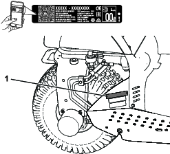
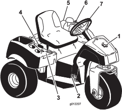
Whenever you need service, genuine Toro parts, or additional information, contact an Authorized Service Dealer or Toro Customer Service and have the model and serial numbers of your product ready. Figure 1 identifies the location of the model and serial numbers on the product. Write the numbers in the space provided.
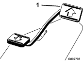
Important: With your mobile device, you can scan the QR code (if equipped) on the serial number decal to access warranty, parts, and other product information.
This manual identifies potential hazards and has safety messages identified by the safety-alert symbol (Figure 2), which signals a hazard that may cause serious injury or death if you do not follow the recommended precautions.

This manual uses 2 words to highlight information. Important calls attention to special mechanical information and Note emphasizes general information worthy of special attention.
This product complies with all relevant European directives. For details, please see the separate product specific Declaration of Conformity (DOC) sheet.
It is a violation of California Public Resource Code Section 4442 or 4443 to use or operate the engine on any forest-covered, brush-covered, or grass-covered land unless the engine is equipped with a spark arrester, as defined in Section 4442, maintained in effective working order or the engine is constructed, equipped, and maintained for the prevention of fire.
The enclosed engine owner's manual is supplied for information regarding the US Environmental Protection Agency (EPA) and the California Emission Control Regulation of emission systems, maintenance, and warranty. Replacements may be ordered through the engine manufacturer.
Warning
CALIFORNIA
Proposition 65 Warning
The engine exhaust from this product contains chemicals known to the State of California to cause cancer, birth defects, or other reproductive harm.
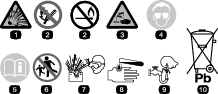
Battery posts, terminals, and related accessories contain lead and lead compounds, chemicals known to the State of California to cause cancer and reproductive harm. Wash hands after handling.
Use of this product may cause exposure to chemicals known to the State of California to cause cancer, birth defects, or other reproductive harm.
Safety
This machine has been designed in accordance with ANSI B71.4-2017. However, when attachments are installed on the machine, additional weight is required to comply to the standards.
General Safety
This product is capable of causing personal injury. Always follow all safety instructions to avoid serious personal injury.
-
Read and understand the contents of this Operator’s Manual before starting the engine. Ensure that everyone using this product knows how to use it and understands the warnings.
-
Use your full attention while operating the machine. Do not engage in any activity that causes distractions; otherwise, injury or property damage may occur.
-
Do not put your hands or feet near moving components of the machine.
-
Do not operate the machine without all guards and other safety protective devices in place and working on the machine.
-
Keep the machine a safe distance away from bystanders while it is moving.
-
Keep children out of the operating area. Never allow children to operate the machine.
-
Stop the machine and shut off the engine before servicing or fueling the machine.
Improperly using or maintaining this machine can result in injury.
To reduce the potential for injury, comply with these safety instructions
and always pay attention to the safety-alert symbol  , which means Caution, Warning,
or Danger—personal safety instruction. Failure to comply with
these instructions may result in personal injury or death.
, which means Caution, Warning,
or Danger—personal safety instruction. Failure to comply with
these instructions may result in personal injury or death.
You can find additional safety information where needed throughout this manual.
Safety and Instructional Decals
 |
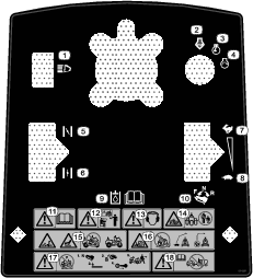
Safety decals and instructions are easily visible to the operator and are located near any area of potential danger. Replace any decal that is damaged or missing. |


Setup
Note: Determine the left and right sides of the machine from the normal operating position.
Note: Remove and discard all the shipping brackets and fasteners.
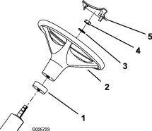
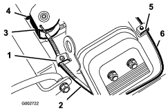
Installing the Steering Wheel
Parts needed for this procedure:
| Steering wheel | 1 |
| Foam collar | 1 |
| Washer | 1 |
| Locknut | 1 |
| Steering-wheel cover | 1 |
-
Move the front wheel so that it points straight ahead.
-
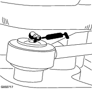
Slide the foam collar, small end first, onto the steering shaft (Figure 3).
-
Slide the steering wheel onto the steering shaft (Figure 3).
-
Secure the steering wheel to the steering shaft with a washer and a locknut (Figure 3).
-
Torque the locknut to 27 to 35 N∙m (20 to 26 ft-lb).
-
Press the steering-wheel cover into position on the steering wheel (Figure 3).
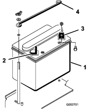
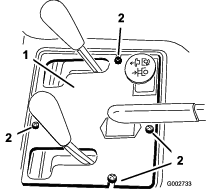
Removing the Battery
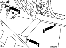
Remove the 2 wing nuts and washers securing the top battery hold-down to the side battery hold-downs (Figure 4). Remove the top battery hold-down and remove the battery.
Activating and Charging the Battery
Parts needed for this procedure:
| Bulk electrolyte, 1.260 specific gravity (not included) | – |
If the battery is not filled with electrolyte or activated, add electrolyte with 1.260 specific gravity to the battery.
Note: You can purchase bulk electrolyte from a local battery supply outlet.
Danger
Battery electrolyte contains sulfuric acid, which is fatal if consumed and causes severe burns.
-
Do not drink electrolyte and avoid contact with skin, eyes, or clothing. Wear safety glasses to shield your eyes and rubber gloves to protect your hands.
-
Fill the battery where clean water is always available for flushing the skin.
-
Remove the filler caps from the battery and slowly fill each cell until electrolyte is up to the fill line.
-
Replace the filler caps and connect a 3 to 4 A battery charger to the battery posts. Charge the battery at a rate of 3 to 4 A for 4 to 8 hours.
Warning
Charging the battery produces gasses that can explode.
Never smoke near the battery and keep sparks and flames away from battery.
-
When the battery is charged, disconnect the charger from the electrical outlet and battery posts. Allow the battery to sit for 5 to 10 minutes.
-
Remove the filler caps.
-
Slowly add electrolyte to each cell until the level is up to the fill line.
Important: Do not overfill the battery. Electrolyte will overflow onto other parts of the machine and severe corrosion and deterioration will result.
-
Install the filler caps.
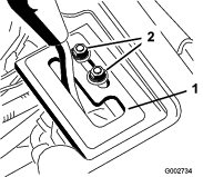
Installing the Battery
Parts needed for this procedure:
| Bolt (1/4 x 5/8 inch) | 2 |
| Locknut (1/4 inch) | 2 |
-
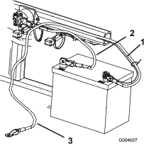
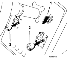
Set the battery in place, with the negative terminal positioned to the rear of the machine (Figure 5).
Warning
Incorrect battery cable routing could damage the machine and cables and cause sparks. Sparks can cause the battery gasses to explode, resulting in personal injury.
-
Always disconnect the negative (black) battery cable before disconnecting the positive (red) cable.
-
Always connect the positive (red) battery cable before connecting the negative (black) cable.
Warning
Battery terminals or metal tools could short against metal machine components, causing sparks. Sparks can cause the battery gasses to explode, resulting in personal injury.
-
When removing or installing the battery, do not allow the battery terminals to touch any metal parts of the machine.
-
Do not allow metal tools to short between the battery terminals and metal parts of the machine.
-
-
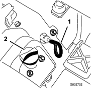
Secure the positive cable (red) to the positive (+) terminal with a bolt (1/4 x 5/8 inch) and a locknut (Figure 6).
-
Secure the small black wire and the negative cable (black) to the negative (-) terminal of the battery with a bolt (1/4 x 5/8 inch) and locknut (1/4 inch) (Figure 6).
-
Coat the terminals and mounting fasteners with petroleum jelly to prevent corrosion.
-
Slide the rubber boot over the positive (+) terminal to prevent a possible short from occurring.
-
Install the top battery hold-down to the side battery hold-downs and secure it with the washers and wing nuts.
Installing Front Weights
Parts needed for this procedure:
| Front weight kit(s) as needed | – |
This machine has been designed in accordance with ANSI B71.4-2017. However, when attachments are installed on the machine additional weight may be required to comply to the standards.
-
Use the chart below to determine the combinations of additional weight required. Order parts from your authorized Toro distributor.
Attachment Weight Required Weight Kit Kit Quantity Spiker Kit 23 kg (50 lb) Part No. 100-6442 1 Rahn Groomer Note: For Model 08705 machines, do not install the weight kit if your machine is equipped with the front lift frame kit.
-
Install the weight kit; refer to the Installation Instructions for the weight kit.
Applying the Production Year Decal
CE Only
Parts needed for this procedure:
| Production year decal | 1 |
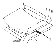
Apply the production year decal to the machine in the area shown (Figure 7).
Replacing the Warning Decal for CE Compliance
Parts needed for this procedure:
| Warning decal | 1 |
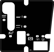
On machines requiring CE compliance, affix the CE warning decal (Part No. 136-6164) over the bottom area of the console decal (Part No. 132-4422).
Product Overview
Traction and Stopping Pedal
The traction pedal (Figure 9) has 3 functions: to move the machine forward, to move it backward, and to stop the machine. Using the heel and toe of your right foot, press the top of the pedal to move forward and the bottom of the pedal to move backward or to assist in stopping when moving forward (Figure 10). Allow the pedal to move or move it to the NEUTRAL position to stop the machine.
Important: When driving the machine forward, rest your heel on the foot rest; do not rest your heal on the reverse pad of the traction pedal.

The ground speed is proportionate to how far you press the traction pedal. For maximum ground speed, press the pedal fully while the throttle is in the FAST position. To get maximum power or when ascending a hill, have the throttle in the FAST position while pressing the pedal slightly to keep the engine speed high. When the engine speed begins to decrease, release the pedal slightly to allow the speed to increase.
Important: For maximum pulling power, move the throttle to the FAST position and lightly press the traction pedal.
Important: Use the maximum ground speed only when driving between job sites.Do not use the maximum speed when using a mounted or towed attachment.
Important: Do not operate the machine in reverse with the attachment in the down (operating) position, or the attachment could be severely damaged.
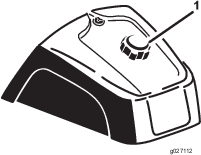
Ignition Switch
The ignition switch (Figure 11), used to start and shut off the engine, has 3 positions: OFF, RUN, and START. Rotate the key clockwise to the START position to engage the starter motor. Release the key when the engine starts, and the key moves to the ON position. To shut the engine off, rotate the key counterclockwise to the OFF position.
Choke Control
To start a cold engine, close the carburetor choke by moving the choke control (Figure 11) up to the CLOSED position. After the engine starts, regulate the choke to keep the engine running smoothly. As soon as possible, open the choke by moving it down to the OPEN position. A warm engine requires little or no choking.
Throttle Control
The throttle control lever (Figure 11) connects to and operates the throttle linkage to the carburetor. The control has 2 positions: SLOW and FAST. The engine speed can be varied between the 2 settings.
Note: You cannot shut off the engine by using the throttle control.
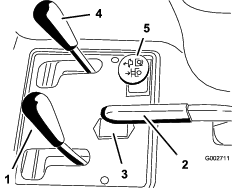
Lift Lever
To raise the attachment, pull the lift lever (Figure 12) back; to lower the attachment, push the lever forward. For the FLOAT position, move the lever into the detent position. When you attain the desired position, release the lever and it will return to neutral.
Note: The machine has a double-acting lift cylinder. You can apply down pressure to the attachment for certain operating conditions.
Parking Brake
To engage the parking brake (Figure 12), pull back on the parking-brake lever. To disengage it, push the lever forward.
Note: You may have to rotate the traction pedal slowly forward and backward to disengage the parking brake.
Hour Meter
The hour meter (Figure 12) indicates the total hours of machine operation. The hour meter starts to function whenever you rotate the key switch to the ON position.
Seat-Adjustment Lever
Move the lever on the left side of the seat (Figure 13) forward, slide the seat to the desired position, and release the lever to lock the seat into position.
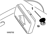
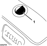
Fuel-Shutoff Valve
Close the fuel-shutoff valve (Figure 14) when storing the machine or transporting it on a trailer.
Note: Specifications and design are subject to change without notice.
| Width without attachment | 148 cm (58 inches) |
| Width with rake, Model 08751 | 191 cm (75 inches) |
| Length without attachment | 164 cm (64-1/2 inches) |
| Height | 115 cm (45-1/4 inches) |
| Wheelbase | 109 cm (42-3/4 inches) |
| Net weight | |
| Model 08703 | 452 kg (996 lb) |
| Model 08705 | 461 kg (1,017 lb) |
Attachments/Accessories
A selection of Toro approved attachments and accessories is available for use with the machine to enhance and expand its capabilities. Contact your Authorized Service Dealer or authorized Toro distributor or go to www.Toro.com for a list of all approved attachments and accessories.
To ensure optimum performance and continued safety certification of the machine, use only genuine Toro replacement parts and accessories. Replacement parts and accessories made by other manufacturers could be dangerous, and such use could void the product warranty.
Operation
Before Operation
Before Operation Safety
General Safety
-
Park the machine on a level surface; engage the parking brake; shut off the engine; remove the key; and wait for all movement to stop before leaving the machine.
-
Never allow children or untrained people to operate or service the machine. Local regulations may restrict the age of the operator. The owner is responsible for training all operators and mechanics.
-
Become familiar with the safe operation of the equipment, operator controls, and safety signs.
-
Know how to stop the machine and engine quickly.
-
Check that operator-presence controls, safety switches, and shields are attached and functioning properly. Do not operate the machine unless they are functioning properly.
-
Before operating, always inspect the machine to ensure that the components and fasteners are in good working condition. Replace worn or damaged components and fasteners.
-
Inspect the area where you will use the machine and remove all objects that the machine could throw.
Fuel Safety
-
Use extreme care in handling fuel. It is flammable and its vapors are explosive.
-
Extinguish all cigarettes, cigars, pipes, and other sources of ignition.
-
Use only an approved fuel container.
-
Do not remove the fuel cap or fill the fuel tank while the engine is running or hot.
-
Do not add or drain fuel in an enclosed space.
-
Do not store the machine or fuel container where there is an open flame, spark, or pilot light, such as on a water heater or other appliance.
-
If you spill fuel, do not attempt to start the engine; avoid creating any source of ignition until the fuel vapors have dissipated.
Filling the Fuel Tank
-
Fuel-tank capacity: 25 L (5-1/2 US gallons).
-
Recommended fuel:
-
For best results, use only clean, fresh (less than 30 days old), unleaded gasoline with an octane rating of 87 or higher ((R+M)/2 rating method).
-
Ethanol: Gasoline with up to 10% ethanol (gasohol) or 15% MTBE (methyl tertiary butyl ether) by volume is acceptable. Ethanol and MTBE are not the same. Gasoline with 15% ethanol (E15) by volume is not approved for use. Never use gasoline that contains more than 10% ethanol by volume, such as E15 (contains 15% ethanol), E20 (contains 20% ethanol), or E85 (contains up to 85% ethanol). Using unapproved gasoline may cause performance problems and/or engine damage which may not be covered under warranty.
-
Do not use gasoline containing methanol.
-
Do not store fuel either in the fuel tank or fuel containers over the winter unless a fuel stabilizer is used.
-
Do not add oil to gasoline.
Important: Do not use fuel additives other than a fuel stabilizer/conditioner. Do not use fuel stabilizers with an alcohol base such as ethanol, methanol, or isopropanol.
-
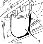
-
Clean the area around the fuel-tank cap (Figure 15).
-
Remove the fuel-tank cap.
-
Fill the tank to about 25 mm (1 inch) below the top of the tank (bottom of the filler neck). Do not overfill.
-
Install the cap.
-
Wipe up any fuel that may have spilled to prevent a fire hazard.
Important: Never use methanol, gasoline containing methanol, or gasohol containing more than 10% ethanol because the fuel system could be damaged. Do not mix oil with gasoline.
Before Operations Checks
Perform the following daily procedures before operating the machine:
Checking the Interlock System
Caution
If safety interlock switches are disconnected or damaged the machine could operate unexpectedly and cause personal injury.
-
Do not tamper with the interlock switches.
-
Check the operation of the interlock switches daily and replace any damaged switches before operating the machine.
The purpose of the interlock system is to prevent the engine from cranking or starting unless the traction pedal is in the NEUTRAL position. Also, the engine should shut off if the traction pedal is moved either forward or reverse without an operator in the seat.
-
Position the machine in a wide-open area free of debris and bystanders. Shut off the engine.
-
Sit on the seat and engage the parking brake.
-
Press the traction pedal in forward and reverse while trying to start the engine.
Note: If the engine cranks, there may be a malfunction in the interlock system. Repair it immediately.If the engine does not crank, the system is operating correctly.
-
Stay seated on the seat, with the traction pedal in the NEUTRAL position and the parking brake engaged, and start the engine.
-
Rise off the seat and slowly press the traction pedal.
Note: The engine should shut off in 1 to 3 seconds. Correct the problem if the system does not operate properly.
During Operation
Note: Determine the left and right sides of the machine from the normal operating position.
General Safety
-
The owner/operator can prevent and is responsible for accidents that may cause personal injury or property damage.
-
Wear appropriate clothing, including eye protection; slip-resistant, substantial foot protection; long pants; and hearing protection. Tie back long hair and do not wear loose jewelry.
-
Do not operate the machine while ill, tired, or under the influence of alcohol or drugs.
-
Never carry passengers on the machine and keep bystanders and pets away from the machine during operation.
-
Operate the machine only in good visibility to avoid holes or hidden hazards.
-
Avoid operating on wet grass. Reduced traction could cause the machine to slide.
-
Before you start the engine, ensure that all drives are in neutral, the parking brake is engaged, and you are in the operating position.
-
Look behind and down before backing up to be sure of a clear path.
-
Use care when approaching blind corners, shrubs, trees, or other objects that may obscure your vision.
-
Do not operate near drop-offs, ditches, or embankments. The machine could suddenly roll over if a wheel goes over the edge or if the edge gives way.
-
Stop the machine and inspect the attachment after striking an object or if there is an abnormal vibration in the machine. Make all necessary repairs before resuming operation.
-
Slow down and use caution when making turns and crossing roads and sidewalks with the machine. Always yield the right-of-way.
-
Never run an engine in an area where exhaust gasses are enclosed.
-
Never leave a running machine unattended.
-
Before leaving the operating position, do the following:
-
Park the machine a level surface.
-
Lower the attachments.
-
Engage the parking brake.
-
Shut off the engine and remove the key.
-
Wait for all moving parts to stop.
-
-
Do not operate the machine when there is the risk of lightning.
-
Do not use the machine as a towing vehicle.
-
When necessary, wet surfaces prior to conditioning to minimize dust creation.
-
Use accessories, attachments, and replacement parts approved by Toro only.
Slope Safety
-
Establish your own procedures and rules for operating on slopes. These procedures must include surveying the site to determine which slopes are safe for machine operation. Always use common sense and good judgment when performing this survey.
-
Slopes are a major factor related to loss of control and rollover accidents, which can result in severe injury or death. The operator is responsible for safe slope operation. Operating the machine on any slope requires extra caution.
-
Slopes are a major factor related to loss-of-control and tip-over accidents, which can result in severe injury or death. Operating the machine on any slope requires extra caution.
-
Operate the machine at a lower speed when you are on a slope.
-
If you feel uneasy operating the machine on a slope, do not do it.
-
Watch for holes, ruts, bumps, rocks, or other hidden objects. Uneven terrain could overturn the machine. Tall grass can hide obstacles.
-
Choose a low ground speed so you will not have to stop or shift while on a slope.
-
A rollover can occur before the tires lose traction.
-
Avoid operating the machine on wet grass. Tires may lose traction; regardless if the brakes are available and functioning.
-
Avoid starting, stopping, or turning the machine on a slope.
-
Keep all movement on slopes slow and gradual. Do not suddenly change the speed or direction of the machine.
-
Do not operate the machine near drop-offs, ditches, embankments, or bodies of water. The machine could suddenly roll over if a wheel goes over the edge or the edge caves in. Establish a safety area between the machine and any hazard (2 machine widths).
Starting and Shutting Off the Engine
-
Remove your foot from the traction pedal, ensure that the pedal is in the NEUTRAL position, and engage the parking brake.
-
Push the choke lever forward to the ON position (when starting a cold engine) and the throttle lever to the SLOW position.
Important: When operating the machine in temperatures less than 0°C (32°F) allow the machine time to warm up before using it. This prevents damage to the hydrostat and the traction loop.
-
Insert the key into the ignition switch and rotate it clockwise to start the engine. Release the key when the engine starts.
Note: Regulate the choke to keep the engine running smoothly.
Important: To prevent overheating the starter motor, do not engage the starter longer than 10 seconds. After 10 seconds of continuous cranking, wait 60 seconds before engaging the starter motor again.
-
To shut off the engine, move the throttle control to the SLOW position and rotate the ignition key to OFF.
Note: Remove the key from the switch to prevent accidental starting.
-
Close the fuel-shutoff valve before storing the machine.
Caution
Inspecting the machine while the engine is running could result in injury.
Shut the engine off and wait for all moving parts to stop before checking for oil leaks, loose parts, and other malfunctions.
Breaking in the Machine
New engines take time to develop full power. Drive systems have more friction when they are new, placing additional load on the engine.
Allow the first 8 hours of operating time for the break-in period.
Since the first hours of operation are critical to future dependability of the machine, monitor the functions and performance closely so that you can notice and correct minor difficulties, which could lead to major problems. Inspect the machine frequently during the break-in period, for signs of oil leakage, loose fasteners, or any other malfunction.
Becoming Familiar with the Machine
Refer to the attachment Operator's Manual for specific operating instructions for the attachment.
Practice driving the machine, because its operating characteristics are different than some utility vehicles. 2 points to consider when operating the vehicle are transmission speed and engine speed.
To maintain constant engine speed, press the traction pedal slowly. This allows the engine to keep up with the ground speed of the vehicle. By contrast, pushing down quickly on the traction pedal reduces the engine speed; as a result, there will not be enough torque-power to move the vehicle. Therefore, to transfer maximum power to the wheels, move the throttle to FAST and slightly press the traction pedal. By comparison, maximum ground speed with no load results when the throttle is in the FAST position and the traction pedal is slowly but fully pressed. Always keep the engine speed high enough to deliver maximum torque-power to the wheels.
Caution
Operating the machine demands attention to prevent tipping or loss of control.
-
Use care when entering and leaving sand traps.
-
Use extreme caution around ditches, creeks, or other hazards.
-
Use caution when operating the machine on a steep slope.
-
Reduce your speed when making sharp turns or when turning on hillsides.
-
Avoid sudden stops and starts.
-
Do not go from reverse to full forward without first coming to a complete stop.
Note: If the attachment adapter becomes stuck to the traction unit adapter, insert a pry bar or a screwdriver into the pry slot to disengage the parts (Figure 16).
After Operation
After Operation Safety
-
Park the machine on a level surface; engage the parking brake; shut off the engine; remove the key; and wait for all movement to stop before leaving the machine.
-
Clean grass and debris from the muffler and engine compartment to help prevent fires. Clean up oil or fuel spills.
-
Allow the engine to cool before storing the machine in any enclosure.
-
Shut off the fuel before storing or transporting the machine.
-
Never store the machine or fuel container where there is an open flame, spark, or pilot light, such as on a water heater or on other appliances.
-
Keep all parts of the machine in good working condition and all hardware tightened.
-
Replace all worn, damaged, or missing decals.
Towing the Machine
In case of emergency, you can tow the machine for a short distance. However, we do not recommend this as a standard procedure.
Important: Do not tow the machine faster than 1.6 km/h (1 mph), because drive system damage may occur. If you must move the machine more than 50 m (55 yd), transport it on a truck or a trailer. The tires may lock up if you tow the machine too fast. If this occurs, stop towing the machine and wait for the traction circuit pressure to stabilize before resuming towing at a slower speed.
Hauling the Machine
-
Use full-width ramps for loading the machine onto a trailer or truck.
-
Tie the machine down securely.
Maintenance
Note: To obtain an electrical schematic or a hydraulic schematic for your machine, visit www.Toro.com.
Maintenance Safety
-
Before adjusting, cleaning, repairing, or leaving the machine, do the following:
-
Park the machine on a level surface.
-
Move the throttle switch to the low-idle position.
-
Lower the attachment.
-
Ensure that the traction is in neutral.
-
Engage the parking brake.
-
Shut off the engine and remove the key.
-
Wait for all moving parts to stop.
-
Allow machine components to cool before performing maintenance.
-
-
If possible, do not perform maintenance while the engine is running. Keep away from moving parts.
-
Use jack stands to support the machine or components when required.
-
Carefully release pressure from components with stored energy.
Recommended Maintenance Schedule(s)
| Maintenance Service Interval | Maintenance Procedure |
|---|---|
| After the first 8 hours |
|
| Before each use or daily |
|
| After each use |
|
| Every 25 hours |
|
| Every 100 hours |
|
| Every 200 hours |
|
| Every 500 hours |
|
| Every 800 hours |
|
| Every 1,000 hours |
|
| Every 1,500 hours |
|
| Every 2,000 hours |
|
Important: Refer to your engine owner's manual for additional maintenance procedures.
Pre-Maintenance Procedures
Note: Determine the left and right sides of the machine from the normal operating position.
Caution
If you leave the key in the ignition switch, someone could accidently start the engine and seriously injure you or other bystanders.
Remove the key from the ignition before you do any maintenance.
Important: The fasteners on the covers of this machine are designed to remain on the cover after removal. Loosen all the fasteners on each cover a few turns so that the cover is loose but still attached, then go back and loosen them until the cover comes free. This prevents you from accidentally stripping the bolts free of the retainers.
Lifting the Machine
Warning
Mechanical or hydraulic jacks may fail to support the machine and cause serious injury.
Use jack stands when supporting the machine.
The jacking points are as follows:
Lubrication
The machine has grease fittings that must be lubricated regularly with No. 2 lithium grease after every 100 hours of operation.
Lubricate the following bearings and bushings:
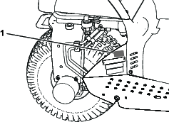
-
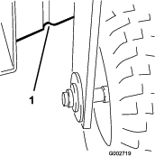
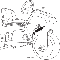
Front wheel bearing (1) (Figure 19)
-
Traction-pedal pivot (1) (Figure 20)
-
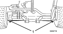
Rear hitch (5) (Figure 21)
-
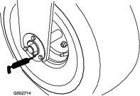
Steering cylinder rod end (1)—Model 08705 only (Figure 22)
-
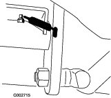
Steering pivot (Figure 23)
Note: The flush fitting on the steering pivot (Figure 23) requires a grease gun nozzle adapter. Order Toro Part No. 107-1998 from your authorized Toro distributor.
Greasing the Machine
| Maintenance Service Interval | Maintenance Procedure |
|---|---|
| Every 100 hours |
|
-
Wipe the grease fitting clean so that foreign matter cannot be forced into the bearing or bushing.
-
Pump grease into the bearing or bushing.
-
Wipe up excess grease.
Engine Maintenance
Engine Safety
-
Shut off the engine before checking the oil or adding oil to the crankcase.
-
Do not change the governor speed or overspeed the engine.
Engine Oil Specification
Use high-quality engine oil that meets the following specifications:
API classification level: SL or higher
Oil Viscosity: SAE 30—above 4°C (40°F)
Checking the Engine-Oil Level
| Maintenance Service Interval | Maintenance Procedure |
|---|---|
| Before each use or daily |
|
The engine is shipped with oil in the crankcase; however, you must check the oil level before and after you first start the engine.
-
Park the machine on a level surface, shut off the engine, engage the parking brake, and remove the key.
-
Pivot the seat forward.
-
Pull out the dipstick (Figure 24) and wipe it with a clean rag.
-
Insert the dipstick into the tube and make sure that it is fully seated. Remove the dipstick from the tube and check the oil level. If the oil level is low, remove the filler cap from the valve cover and add enough of the specified oil to raise the level to the Full mark on the dipstick.
Important: Be sure to keep the oil level between the upper and lower mark on the dipstick. If you overfill or underfill the engine oil, you may damage engine when running it.
-
Install the dipstick firmly in place.
Important: You must fully seat the dipstick in the tube to proper seal the engine crankcase. Failure to seal the crankcase may result in engine damage.
-
Pivot the seat down.
Changing the Engine Oil and Filter
| Maintenance Service Interval | Maintenance Procedure |
|---|---|
| Every 100 hours |
|
Crankcase oil capacity: approximately 1.66 L (1-3/4 US qt) with the filter.
-
Park the machine on a level surface, shut off the engine, engage the parking brake, and remove the key.
-
Remove the drain plug (Figure 25) and let the oil flow into a drain pan. When the oil stops, install the drain plug.
-
Remove the oil filter (Figure 25).
-
Apply a light coat of clean oil to the new filter gasket.
-
Thread the filter on by hand until the gasket contacts the filter adapter; then tighten 1/2 to 3/4 turn further.
Important: Do not overtighten the filter.
-
Add the specified oil to the crankcase; refer to Checking the Engine-Oil Level.
-
Dispose of the used oil properly.
Servicing the Air Cleaner
| Maintenance Service Interval | Maintenance Procedure |
|---|---|
| Every 200 hours |
|
-
Check the body of the air cleaner for damage that could cause an air leak. Replace any damaged components. Check the whole intake system for leaks, damage, or loose hose clamps.
-
Do not change the air filter before it is necessary; doing so only increases the chance of dirt entering the engine when you remove the filter.
-
Be sure that the cover is seated correctly and seals with the body of the air cleaner.
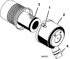
Replacing the Air Filter
| Maintenance Service Interval | Maintenance Procedure |
|---|---|
| Every 200 hours |
|
-
Release the latches securing the air-cleaner cover to the air-cleaner body (Figure 26).
-
Remove the cover from the air-cleaner body.
-
Before removing the filter, use low-pressure air (40 psi, clean and dry) to help remove large accumulations of debris packed between the outside of the primary filter and the canister.
Important: Avoid using high-pressure air, which could force dirt through the filter into the intake tract. This cleaning process prevents debris from migrating into the intake when the primary filter is removed.
-
Remove and replace the filter.
Note: Inspect the new filter for shipping damage, checking the sealing end of the filter and the body. Do not use a damaged element. Insert the new filter by applying pressure to the outer rim of the element to seat it in the canister. Do not apply pressure to the flexible center of the filter.
Note: Cleaning the used element is not recommended due to the possibility of damaging the filter media.
-
Clean the dirt-ejection port located in the removable cover.
-
Remove the rubber outlet valve from the cover, clean the cavity, and replace the outlet valve.
-
Install the cover, orienting the rubber outlet valve in a downward position—between approximately 5 o’clock to 7 o’clock when viewed from the end.
-
Secure the latches.
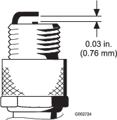
Replacing the Spark Plugs
| Maintenance Service Interval | Maintenance Procedure |
|---|---|
| Every 100 hours |
|
Type: Champion RC14YC (or equivalent)
Air Gap: 0.76 mm (0.030 inch)
Note: The spark plugs usually last a long time; however, you should remove and check them whenever the engine malfunctions.
-
Clean the area around each spark plug so that foreign matter cannot fall into the cylinder when the spark plug is removed.
-
Pull the spark-plug wires off the spark plugs and remove the plugs from the cylinder head.
-
Check the condition of the side electrode, center electrode, and the insulator to ensure that there is no damage.
Important: Replace a cracked, fouled, dirty, or otherwise malfunctioning spark plug. Do not sand-blast, scrape, or clean the electrodes using a wire brush because grit may eventually release from the plug, fall into the cylinder, and damaged the engine.
-
Set the air gap between the center electrode and side electrodes to 0.76 mm (0.030 inch); refer to Figure 27. Install the correctly gapped spark plug with the gasket seal, and tighten the plug to 23 N∙m (200 in-lb). If a torque wrench is not used, tighten the plug firmly.
Fuel System Maintenance
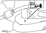
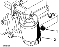
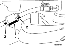
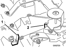
Replacing the Fuel Filter
| Maintenance Service Interval | Maintenance Procedure |
|---|---|
| Every 500 hours |
|
An in-line filter is incorporated into the fuel line. Use the following procedures when replacement becomes necessary:
-
Close the fuel-shutoff valve, loosen the hose clamp on the carburetor side of the filter, and remove the fuel line from the filter (Figure 28).
-
Place a drain pan under the filter, loosen the remaining hose clamp, and remove the filter.
-
Install the new filter with the arrow on the filter body pointing away from the fuel tank (toward the carburetor).
-
Slide the hose clamps onto the ends of the fuel lines.
-
Push the fuel lines onto the fuel filter and secure them with the hose clamps.
Note: Be sure that the arrow on the side of the filter points toward the carburetor.
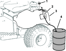
Changing the Carbon-Canister Filter
| Maintenance Service Interval | Maintenance Procedure |
|---|---|
| Every 500 hours |
|
-
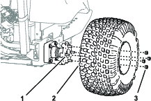
Raise the right rear tire off the ground, and support the machine with jack stands.
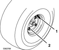
-
Remove the 4 wheel nuts that secure the wheel to the hub, and remove the wheel and tire (Figure 29).
-
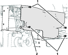
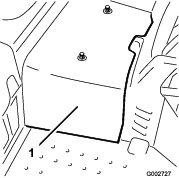
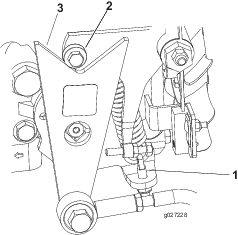
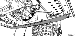
Remove the 4 flange capscrews (1/4 x 5/8 inch) that secure the wheel shroud to the frame of the machine (Figure 30).
-
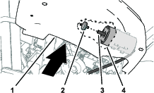
Reaching around the lower, inboard edge of the console, pull the carbon-canister filter rearward and out of the hose at the end of the carbon canister (Figure 31).
-
Insert a new carbon-canister filter into the hose at the end of the carbon canister (Figure 31).
-
Align the holes in the wheel shroud with the frame of the machine (Figure 30), and secure the shroud to the frame with 4 flange capscrews (1/4 x 5/8 inch) that you removed in step 3.
-
Assemble the tire and wheel into the studs of the wheel hub (Figure 29) with the 4 wheel nuts that you removed in step 2, and tighten the nuts by hand.
-
Remove the jack stand and lower the machine to the ground.
-
Torque the wheel nuts; refer to Torquing the Wheel Lug Nuts.
Electrical System Maintenance
Electrical System Safety
-
Disconnect the battery before repairing the machine. Disconnect the negative terminal first and the positive last. Connect the positive terminal first and the negative last.
-
Charge the battery in an open, well-ventilated area, away from sparks and flames. Unplug the charger before connecting or disconnecting the battery. Wear protective clothing and use insulated tools.
Jump-Starting the Machine
If you need to jump-start the machine, you can use the alternative positive post (located on the starter solenoid) instead of the positive battery post (Figure 32).
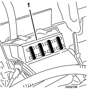
Replacing Fuses
The fuse block (Figure 33) is located under the seat.
Maintaining the Battery
| Maintenance Service Interval | Maintenance Procedure |
|---|---|
| Every 25 hours |
|
Maintain the proper battery electrolyte level and keep the top of the battery clean. If the machine is stored in a location where temperatures are extremely high, the battery runs down more rapidly than if the machine is stored in a location where temperatures are cool.
Keep the top of the battery clean by washing it periodically with a brush dipped in ammonia or baking-soda solution. Flush the top surface with water after cleaning. Do not remove the fill cap while cleaning.
The battery cables must be tight on the terminals to provide good electrical contact.
If corrosion occurs at the battery terminals, disconnect the cables, negative (-) cable first, and scrape the clamps and terminals separately. Connect the cables, positive (+) cable first, and coat the terminals with petroleum jelly.
-
Check the electrolyte level every 25 operating hours, or if the machine is in storage, every 30 days.
-
Maintain the cell level with distilled or demineralized water. Do not fill the cells above the fill line.
Drive System Maintenance
Checking the Tire Pressure
| Maintenance Service Interval | Maintenance Procedure |
|---|---|
| Before each use or daily |
|
Check the tire pressure before operating the machine (Figure 34). The correct air pressure in the front and rear tires is as follows:
-
Treaded tires: 70 kPa (10 psi)
Note: If additional traction is required for blade operation, reduce the pressure to 55 kPa (8 psi).
-
Smooth tires: 55 to 70 kPa (8 to 10 psi)
Torquing the Wheel Lug Nuts
| Maintenance Service Interval | Maintenance Procedure |
|---|---|
| After the first 8 hours |
|
| Every 100 hours |
|
Torque the lugs nuts to 95 to 122 N∙m (70 to 90 ft-lb).
Adjusting the Traction Drive for Neutral
If the machine moves when the traction pedal is in the neutral position, adjust the traction cam.
-
Park the machine on a level surface, shut off the engine, engage the parking brake, and remove the key.
-
Loosen the 2 screws securing the center shroud to the machine and remove the shroud (Figure 35).
-
Raise the front wheel and 1 rear wheel off the floor and place support blocks under the frame.
Warning
The front wheel and 1 rear wheel must be raised off the ground, or else the machine will move during the adjustment. This could cause the machine to fall and injure someone under the machine.
Make sure that the machine is adequately supported, with the front wheel and 1 rear wheel raised off the ground.
-
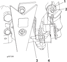
Loosen the locknut on the traction-adjustment cam (Figure 36).
Warning
The engine must be running so that you can perform the final adjustment of the traction-adjustment cam. Contact with moving parts or hot surfaces may cause personal injury.
Keep your hands, feet, face, and other body parts away from rotating parts, the muffler, and other hot surfaces.
-
Start the engine and rotate the cam hex (Figure 36) in both directions to determine the midpoint of the neutral span.
-
Tighten the locknut securing the adjustment.
-
Shut off the engine.
-
Install the center shroud.
-
Remove the jack stands and lower the machine to the shop floor.
-
Test drive the machine to ensure that it does not move when the traction pedal is in neutral.
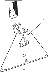
Adjusting the Traction Interlock Switch
-
Adjust the transmission for neutral; refer to Adjusting the Traction Drive for Neutral.
-
Activate the pump lever to ensure that all parts are operating freely and seated properly.
-
Adjust the screw until the air gap is 0.8 to 2.3 mm (0.030 to 0.090 inch); refer to Figure 36.
-
Check for proper operation.
Adjusting the Transport Speed
Obtaining Maximum Transport Speed
The traction pedal is adjusted for maximum transport speed and reverse at the factory, but an adjustment may be required if the pedal reaches full stroke before the pump lever reaches full stroke, or if a decrease in transport speed is desired.
To obtain maximum transport speed, press down on the traction pedal. If the pedal contacts the stop (Figure 37) before the pump lever reaches full stroke, adjust it:
-
Park the machine on a level surface, shut off the engine, engage the parking brake, and remove the key.
-
Loosen the nut securing the pedal stop.
-
Tighten the pedal stop until it does not contact the traction pedal.
-
Continue applying a light load on the transport pedal and adjust the pedal stop so that it just contacts or a gap of 2.5 mm (0.100 inch) is attained between the pedal rod and the stop.
-
Tighten the nuts.
Reducing the Transport Speed
-
Park the machine on a level surface, shut off the engine, engage the parking brake, and remove the key.
-
Loosen the nut securing the pedal stop.
-
Thread the pedal stop out until the desired transport speed is attained.
-
Tighten the nut securing the pedal stop.
Controls System Maintenance
Adjusting the Lift Lever
Adjust the detent plate of the lift lever (Figure 39) if the attachment does not float properly (follow ground contour) during operation.
-
Park the machine on a level surface, shut off the engine, engage the parking brake, and block the wheels.
-
Remove the 4 screws securing the control panel to the frame (Figure 38).
-
Loosen the 2 bolts securing the detent plate to the fender and the frame.
Warning
The engine must be running so that you can adjust the detent plate. Contact with moving parts or hot surfaces may cause personal injury.
Keep your hands, feet, face, and other body parts away from rotating parts, the muffler, and other hot surfaces.
-
Start the engine.
-
With the engine running and the lift lever in the FLOAT position, slide the detent plate until the lift cylinder can be extended and retracted by hand.
-
Tighten both mounting screws to secure the adjustment.
Adjusting the Engine Controls
Adjusting the Throttle Control
Proper throttle operation is dependent upon proper adjustment of the throttle control. Before adjusting the carburetor, ensure that the throttle control is operating properly.
-
Pivot the seat upward.
-
Loosen the throttle cable-clamp screw securing the cable to the engine (Figure 40).
-
Move the remote throttle-control lever forward to the FAST position.
-
Pull firmly on the throttle cable until the back of the swivel contacts the stop (Figure 40).
-
Tighten the cable clamp screw and check the engine speed:
-
High idle: 3,350 to 3,450 rpm
-
Low idle: 1,650 to 1,850 rpm
-
Adjusting the Choke Control
Adjusting the Engine-Governor Speed Control
Important: Before you adjust the engine-governor speed control, ensure that the throttle and choke controls are adjusted properly.
Warning
The engine must be running during adjustment of the engine-governor speed control. Contact with moving parts or hot surfaces may cause personal injury.
-
Ensure that the traction pedal is in neutral and engage the parking brake before performing this procedure.
-
Keep your hands, feet, clothing, and other body parts away from any rotating parts, the muffler, and other hot surfaces.
Note: To adjust the low idle, use all the following steps. If only the high idle is to be adjusted, proceed directly to step 5.
-
Start the engine and let it run at half throttle for approximately 5 minutes to warm up.
-
Move the throttle control to the SLOW setting. Adjust the idle stop screw counterclockwise until it no longer contacts the throttle lever.
-
Bend the governed idle spring anchor tang (Figure 41) to attain an idle speed of 1,675 to 1,175 rpm.
Note: Check the speed with a tachometer.
-
Adjust the idle stop screw until the idle speed is increased 25 to 50 rpm over the idle speed set in step 3.
Note: The final idle speed must be 1,650 to 1,850 rpm.
-
Move the throttle control to the FAST position.
-
Bend the high-speed spring anchor tang (Figure 41) to attain a high speed of 3,350 to 3,450 rpm.
Hydraulic System Maintenance
Hydraulic System Safety
-
Seek immediate medical attention if fluid is injected into skin. Injected fluid must be surgically removed within a few hours by a doctor.
-
Ensure that all hydraulic-fluid hoses and lines are in good condition and all hydraulic connections and fittings are tight before applying pressure to the hydraulic system.
-
Keep your body and hands away from pinhole leaks or nozzles that eject high-pressure hydraulic fluid.
-
Use cardboard or paper to find hydraulic leaks.
-
Safely relieve all pressure in the hydraulic system before performing any work on the hydraulic system.
Checking the Hydraulic Lines and Hoses
| Maintenance Service Interval | Maintenance Procedure |
|---|---|
| Before each use or daily |
|
Check the hydraulic lines and hoses daily for leaks, kinked lines, loose mounting supports, wear, loose fittings, weather deterioration, and chemical deterioration. Make all necessary repairs before operating.
Hydraulic Fluid Specifications
The reservoir is filled at the factory with high-quality hydraulic fluid. Check the level of the hydraulic fluid before you first start the engine and daily thereafter; refer to Checking the Hydraulic-Fluid Level.
Recommended hydraulic fluid: Toro PX Extended Life Hydraulic Fluid; available in 19 L (5 US gallon) pails or 208 L (55 US gallon) drums.
Note: A machine using the recommended replacement fluid requires less frequent fluid and filter changes.
Alternative hydraulic fluids: If Toro PX Extended Life Hydraulic Fluid is not available, you may use another conventional, petroleum-based hydraulic fluid having specifications that fall within the listed range for all the following material properties and that it meets industry standards. Do not use synthetic fluid. Consult with your lubricant distributor to identify a satisfactory product.
Note: Toro does not assume responsibility for damage caused by improper substitutions, so use products only from reputable manufacturers who will stand behind their recommendation.
| Material Properties: | ||
| Viscosity, ASTM D445 | cSt @ 40°C (104°F) 44 to 48 | |
| Viscosity Index ASTM D2270 | 140 or higher | |
| Pour Point, ASTM D97 | -37°C to -45°C (-34°F to -49°F) | |
| Industry Specifications: | Eaton Vickers 694 (I-286-S, M-2950-S/35VQ25 or M-2952-S) | |
Note: Many hydraulic fluids are almost colorless, making it difficult to spot leaks. A red dye additive for the hydraulic fluid is available in 20 ml (0.67 fl oz) bottles. A bottle is sufficient for 15 to 22 L (4 to 6 US gallons) of hydraulic fluid. Order Part No. 44-2500 from your authorized Toro distributor.
Important: Toro Premium Synthetic Biodegradable Hydraulic Fluid is the only synthetic biodegradable fluid approved by Toro. This fluid is compatible with the elastomers used in Toro hydraulic systems and is suitable for a wide-range of temperature conditions. This fluid is compatible with conventional mineral oils, but for maximum biodegradability and performance, the hydraulic system should be thoroughly flushed of conventional fluid. The oil is available in 19 L (5 US gallons) pails or 208 L (55 US gallons) from your authorized Toro distributor.
Checking the Hydraulic-Fluid Level
| Maintenance Service Interval | Maintenance Procedure |
|---|---|
| Before each use or daily |
|
The reservoir is filled at the factory with the recommended hydraulic fluid. The best time to check the hydraulic fluid is when it is cold.
-
Fully raise all hydraulic attachment to the transport position.
-
Park the machine on a level surface, shut off the engine, engage the parking brake, and remove the key.
-
Clean the area around the hydraulic-reservoir cap to prevent debris from entering the tank (Figure 42).
-
Remove the cap from the reservoir.
-
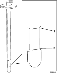
Remove the dipstick from the filler neck and wipe it with a clean rag.
-
Insert the dipstick into the filler neck; then remove it and check the level of the fluid (Figure 43).
When the reservoir is properly filled with hydraulic fluid, you should see the fluid level between the upper and lower marks (necked-down area) on the dipstick.
Important: If the fluid level is between the upper and lower marks, no fluid addition is required.
-
If the fluid level is too low, slowly add the specified hydraulic fluid to the reservoir until the fluid level reaches the necked-down area on the dipstick.
Important: To prevent system contamination, clean the surface of the of hydraulic-fluid containers before opening them. Ensure that the pour spout and the funnel are clean.
Important: Do not overfill the reservoir with hydraulic fluid.
-
Install the reservoir cap.
Replacing the Hydraulic Filter
| Maintenance Service Interval | Maintenance Procedure |
|---|---|
| Every 800 hours |
|
| Every 1,000 hours |
|
-
Park the machine on a level surface, shut off the engine, engage the parking brake, and remove the key.
-
Loosen the 2 screws securing the center shroud to the machine and remove the shroud (Figure 44).
-
Lubricate the sealing gasket on the replacement filter with clean hydraulic fluid.
-
Place a drain pan under the hydraulic filter, which is located at the left side of the machine (Figure 45).
-
Clean the area around the filter mounting area.
Note: Have the replacement filter within reach before removing the old filter.
-
Remove the hydraulic filter from the filter head.
-
Install the new hydraulic filter (Figure 45) by turning it on by hand until the gasket contacts the filter head, then tighten the filter 3/4 turn further.
-
Check the hydraulic fluid level and add the specified hydraulic fluid as needed; refer to Checking the Hydraulic-Fluid Level
-
Install the center shroud.
Changing the Hydraulic Fluid
| Maintenance Service Interval | Maintenance Procedure |
|---|---|
| Every 800 hours |
|
| Every 2,000 hours |
|
Reservoir capacity: 18.9 L (5 US gallons)
Use a genuine Toro filter for replacement; refer to the Parts Catalog for your machine.
-
Remove the cap from the hydraulic reservoir (Figure 46).
-
Pump the hydraulic fluid from hydraulic reservoir (Figure 46).
-
Fill the hydraulic reservoir with the specified hydraulic fluid until the level is up to the necked-down area of the dipstick; refer to Checking the Hydraulic-Fluid Level.
Important: Do not overfill the tank with hydraulic fluid.
-
Start and run the engine. Operate the lift cylinder until it extends and retracts and forward and reverse wheel motion is achieved.
-
Shut off the engine and check the hydraulic-fluid level in the reservoir; add fluid if necessary.
-
Check for leaks.
Repair any hydraulic leaks.
-
Install the center shroud.
Charging the Hydraulic System
Whenever a hydraulic component is repaired or replaced, change the hydraulic filter and charge the hydraulic system.
Ensure that the hydraulic reservoir and the filter are filled with fluid at all times when charging the hydraulic system.
-
Park the machine on a level surface, shut off the engine, engage the parking brake, and remove the key.
-
Loosen the 2 screws securing the center shroud to the machine and remove the shroud (Figure 47).
-
Raise the front wheel and 1 of the rear wheels off the floor and place support blocks under the frame.
Warning
The front wheel and 1 rear wheel must be raised off the ground, or else the machine will move during the adjustment. This could cause the machine to fall and injure someone under the machine.
Make sure that the machine is adequately supported, with the front wheel and 1 rear wheel raised off the ground.
-
Start the engine and set the throttle to allow the engine to run at approximately 1,800 rpm.
-
Actuate the lift-valve lever until the lift-cylinder rod moves in and out several times. If the cylinder rod does not move after 10 to 15 seconds or the pump emits abnormal sounds, shut the engine off immediately and determine the cause or problem. Inspect for the following:
-
Loose filter or suction lines
-
Loose or faulty coupler on the pump
-
Blocked suction line
-
Faulty charge-relief valve
-
Faulty charge pump
If the cylinder moves in 10 to 15 seconds, proceed to step 6.
-
-
Operate the traction pedal in forward and reverse. The wheels that are off the floor should rotate in the proper direction.
-
If the wheels rotate in the wrong direction, shut off the engine, remove the lines from the rear of the pump, and reverse the locations.
-
If the wheels rotate in the proper direction, shut off the engine and adjust the spring-adjusting pin locknut (Figure 48). Adjust the traction neutral position; refer to Adjusting the Traction Drive for Neutral.
-
-
Check the adjustment of the traction interlock switch; refer to Adjusting the Traction Interlock Switch.
-
Install the center shroud.
Cleaning
Cleaning and Inspecting the Machine
| Maintenance Service Interval | Maintenance Procedure |
|---|---|
| After each use |
|
-
Thoroughly wash the machine with a garden hose—without a nozzle—so that excessive water pressure does not cause contamination and damage to the seals and bearings.
Make sure that the cooling fins and the area around the cooling-air intake are kept free of debris.
Important: Cleaning the oil cooler with water promotes premature corrosion and damage to components, and compacts debris; refer to Cleaning the Oil Cooler.
-
Inspect the machine for possible hydraulic-fluid leaks, damage, or wear to hydraulic and mechanical components.
Storage
Preparing the Machine
-
Thoroughly clean the machine, the attachments, and the engine.
-
Park the machine on a level surface; engage the parking brake; shut off the engine; remove the key; and wait for all movement to stop before leaving the machine.
-
Check the tire pressure; refer to Checking the Tire Pressure.
-
Check all fasteners for looseness; tighten as necessary.
-
Grease or oil all grease fittings and pivot points; refer to Greasing the Machine.
-
Lightly sand and use touch-up paint on painted areas that are scratched, chipped, or rusted.
Preparing the Engine
-
Change the engine oil and filter; refer to Changing the Engine Oil and Filter.
-
Start the engine and run it at idle speed for 2 minutes.
-
Shut off the engine; remove the key; and wait for all movement to stop before leaving the machine.
-
Thoroughly clean and service the air-cleaner assembly; refer to Servicing the Air Cleaner.
-
Seal the air-cleaner inlet and the exhaust outlet with weatherproof masking tape.
-
Check the oil-filler cap and the fuel-tank cap to ensure that they are securely in place.
Preparing the Battery
-
Remove the battery terminals from the battery posts.
-
Clean the battery, terminals, and posts with a wire brush and a baking-soda solution.
-
Coat the cable terminals and battery posts with Grafo 112X skin-over grease (Toro Part 505-47) to prevent corrosion.
-
Slowly charge the battery for 24 hours every 60 days to prevent lead sulfation of the battery.
Note: The specific gravity of a fully charged battery measures 1.250.
Note: Store the battery in a cool atmosphere to avoid quick deterioration of the charge in the battery. To prevent the battery from freezing, make sure that it is fully charged.