


Maintenance
Warning
Failure to properly maintain the machine could result in premature failure of machine systems, causing possible harm to you or bystanders.
Keep the machine well maintained and in good working order as indicated in these instructions.
Note: Determine the left and right sides of the machine from the normal operating position. Place a service tag on the machine when maintenance procedures are being performed.Replace all covers and guards after you service or clean the machine. Do not operate the machine without the covers or guards in place.
Note: Download a free copy of the electrical or hydraulic schematic by visiting www.Toro.com and searching for your machine from the Manuals link on the home page.
Important: Refer to your engine owner’s manual for additional maintenance procedures.
Recommended Maintenance Schedule(s)
| Maintenance Service Interval | Maintenance Procedure |
|---|---|
| After the first 100 hours |
|
| After the first 250 hours |
|
| Before each use or daily |
|
| Every 50 hours |
|
| Every 250 hours |
|
| Every 300 hours |
|
| Every 500 hours |
|
| Every 800 hours |
|
| Every 1,000 hours |
|
| Every 2,000 hours |
|
| Yearly or before storage |
|
| Every 2 years |
|
Warning
Improperly servicing or repairing the machine may cause injury or death.
If you do not understand the service procedures for this machine, contact your Authorized Service Dealer or see the service manual for this machine.
Warning
Operating the machine without covers and guards in place may cause personal injury or death.
Replace all covers and guards after you service or clean the machine. Do not operate the machine without the covers or guards in place.
Pre-Maintenance Procedures
Pre-Maintenance Safety
-
Before adjusting, cleaning, repairing, or leaving the machine, do the following:
-
Move the machine on a level surface.
-
Shut off the machine.
-
Turn the battery-disconnect switch to the OFF position.
-
Wait for all moving parts to stop.
-
Allow machine components to cool before performing maintenance.
-
-
If possible, do not perform maintenance while the engine is running. Keep away from moving parts.
-
Use adequate support to support the machine or components when required.
-
Carefully release pressure from components with stored energy.
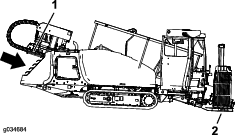
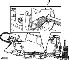
Opening the Front Hood
-
Park the machine on a level surface, stop the engine, and remove the ignition key.
-
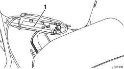
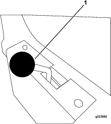
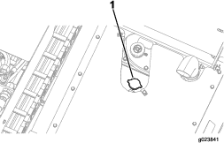
Lift up on the latch as shown in Figure 69.
Note: Ensure that the key is in the OPEN (horizontal) position as shown in Figure 69.
-
Pull up on the hood latch as shown in Figure 70.
-
Keep the hood latch (Figure 70) pulled up, and lift up on the handle as shown in Figure 71.
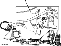
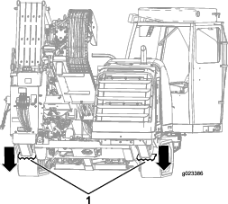
Opening the Rear-Access Door
-
Park the machine on a level surface, stop the engine, and remove the ignition key.
-
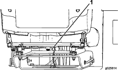
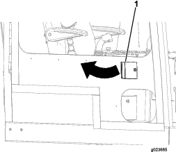
Push on the left side of the panel handle, and pull the panel open when the handle is released (Figure 72).

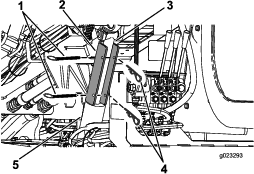
Using the Cylinder Lock
Warning
The thrust frame may lower when it is in the raised position, causing serious injury or death.
Install the cylinder lock before performing maintenance that requires the thrust frame to be raised.
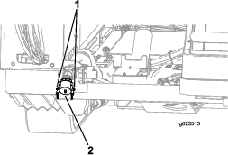
Installing the Cylinder Lock
-
Start the engine.
-
Lower the thrust frame to the fully-lowered position.
-
Stop the engine.
-
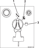
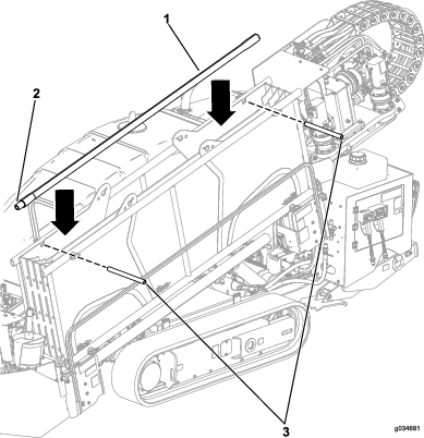
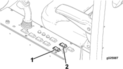
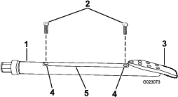
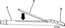
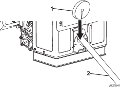
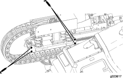
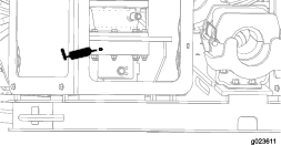
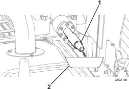
Position the cylinder lock over the cylinder rod (Figure 73).
-
Secure the cylinder lock with the cotter pin and clevis pin (Figure 73).
-
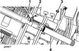
Turn the engine to the ON position, and raise the thrust frame until it rests on the cylinder lock.
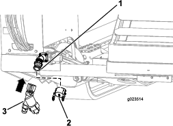
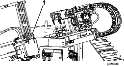
Removing and Storing the Cylinder Lock
-
Start the engine.
-
Lower the thrust frame to the fully lowered position.
-
Stop the engine.
-
Remove the cotter pin and the clevis pin that secure the cylinder lock (Figure 73).
-
Remove the cylinder lock.
-
Turn the engine to the ON position, and raise the thrust frame.
-
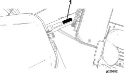
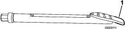
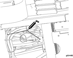
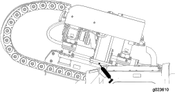
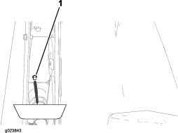
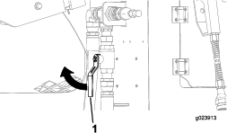
Store the cylinder lock at the rear of the pipe holder (Figure 74).
Lubrication
Greasing the Machine
| Maintenance Service Interval | Maintenance Procedure |
|---|---|
| Before each use or daily |
|
Grease type: General-purpose grease.
-
Park the machine on a level surface, stop the engine, and remove the ignition key.
-
Clean the grease fittings with a rag.
-
Connect a grease gun to each fitting.
-
Pump grease into the fittings until grease begins to ooze out of the bearings (approximately 3 pumps).
-
Wipe up any excess grease.
Engine Maintenance
Engine Safety
-
Shut off the engine before checking the oil or adding oil to the crankcase.
-
Do not change the governor speed or overspeed the engine.
Cleaning the Crankcase-Vent Tube
| Maintenance Service Interval | Maintenance Procedure |
|---|---|
| Before each use or daily |
|
Servicing the Air-Cleaning System
Important: Do not remove the elements from the machine to check for dirty filters; use the following procedure instead.
Important: Do not replace the old air-cleaner filter with a filter that is more than 5 years old; check the date of manufacture on the end cap of the element.
Note: Every time you service the air-cleaner system, ensure that all hose connections and flanges are air tight. Replace all damaged parts.
-
Check the air-cleaner body for damage which could cause an air leak. Replace it if it is damaged. Check the whole intake system for leaks, damage or loose hose clamps. Also, inspect the rubber intake hose connections at the air cleaner and the turbo to make sure that the connections are complete.
-
Service the air-cleaner filter only when “Check Air Filter” is displayed on the screen. Changing the air filter before it is necessary only increases the chance of dirt entering the engine when the filter is removed.
-
Be sure that the cover is seated correctly and seals with the air-cleaner body.
Checking the Air-Cleaner Indicator
| Maintenance Service Interval | Maintenance Procedure |
|---|---|
| Before each use or daily |
|
-
Start the engine.
-
Check the restricted, air-cleaner indicator on the display screen; refer to the Air-Cleaner Indicator Screen in the Software Guide for this machine.
-
Replace the air-filter element(s) as follows:
-
Replace the primary, air-cleaner filter; refer to Servicing the Air-Cleaner Filter.
-
Repeat steps 1 and 2; if the restricted air-cleaner indicator is still shown on the display screen, replace the secondary, air-cleaner filter; refer to Servicing the Air-Cleaner Filter.
-
Cleaning the Dust Valve
| Maintenance Service Interval | Maintenance Procedure |
|---|---|
| Every 50 hours |
|
-
Park the machine on a level surface, stop the engine, and remove the ignition key.
-
Open the rear-access door; refer to Opening the Rear-Access Door.
-
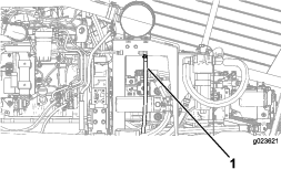
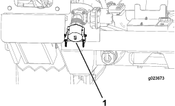
Squeeze the sides of the dust valve on the air-cleaner cover to release any collected water, dust, or dirt from the valve. (Figure 87).
Note: Ensure that there are no obstructions inside the dust valve.
Servicing the Air-Cleaner Cover
| Maintenance Service Interval | Maintenance Procedure |
|---|---|
| Every 50 hours |
|
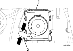
Removing the Air-Cleaner Cover
-
Park the machine on a level surface, stop the engine, and remove the ignition key.
-
Open the rear-access door; refer to Opening the Rear-Access Door.
-
Clean the outside of the air-cleaner canister with a clean, damp cloth.
-
Check the air-cleaner cover for damage which could cause an air leak. Replace a damaged air-cleaner body.
Important: Service the air-cleaner filter only when “Check Air Filter” is displayed on the screen. Changing the air filter before it is necessary only increases the chance of dirt entering the engine when the filter is removed.
-
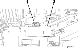
Pull the 4 latches for the air-cleaner cover outward (Figure 88).
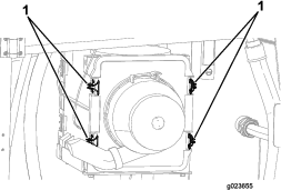
-
Pull the air-cleaner cover away from the filter housing and remove the cover.
-
Clean any debris from inside the cover.
Important: If “Check Air Filter” is not displayed on the screen, do not remove the air filter.
Installing the Air-Cleaner Cover
-
Park the machine on a level surface, stop the engine, and remove the ignition key.
-
Align the dust cap on the air cleaner filter cover.
-
Align the air-cleaner cover with the filter housing.
-
Place air-cleaner cover inward until it is fully seated, and secure it with the latches (Figure 88).
Servicing the Air-Cleaner Filter
| Maintenance Service Interval | Maintenance Procedure |
|---|---|
| Every 250 hours |
|
Replace the filters only when the “Check Air Filter” indicator appears on the display screen; refer to Checking the Air-Cleaner Indicator.
Note: Contact your Authorized Toro Dealer to order replacement filters.
-
Park the machine on a level surface, stop the engine, and remove the ignition key.
-
Open the rear-access door.
-
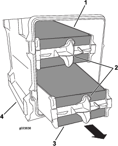
Before removing the filter, clean out all debris from the inside of the filter body using low-pressure air at 275 kPa (40 psi).
Important: Avoid using high pressure air which could force dirt through the filter into the intake tract. This cleaning process prevents debris from migrating into the intake when the primary filter is removed.
-
Using the air-filter handles, remove the primary filter from the air-cleaner cover (Figure 89).
Important: Do not clean the used filter.
-
Inspect the new filter for shipping damage, checking the sealing end of the filter and the body.
Note: Do not use a damaged element.
-
Insert the new primary filter by applying pressure to the outer rim of the filter to seat it in the air-cleaner cover.
-
Remove the rubber outlet valve from the cover, clean the cavity, and replace the outlet valve; refer to Cleaning the Dust Valve.
-
Install the cover; refer to Installing the Air-Cleaner Cover.
Servicing the Engine Oil and Filter
The engine is shipped with oil in the crankcase; however, check the oil level before and after you first start the engine.
Crankcase capacity: 7.5 L (7.9 US qt) with the filter.
Use only high-quality low ash SAE 15W-40 heavy-duty engine oil with an API classification of CJ-4 (ACEA E9) or higher.
While low ash SAE 15W-40 oil with an API classification of CJ-4 (ACEA E9) or higher is recommended for most climates, refer to Figure 90 for oil viscosity recommendations for extreme climates.
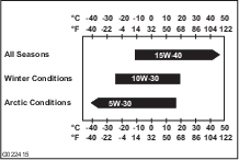
Note: Limited use of low-viscosity oils such as SAE 10W-30 with an API classification of CJ-4 (ACEA E9) or higher can be used for easier starting and providing sufficient oil flow at ambient temperatures below -5°C (23°F). However, continuous use of low viscosity oil can decrease engine life because of wear (Figure 90).
Toro Premium Engine Oil is available from an Authorized Toro Service Dealer in either 15W-40 or 10W-30 viscosity with API classification CJ-4 (ACEA E9) or higher. See the parts catalog for part numbers.
Checking the Engine-Oil Level
| Maintenance Service Interval | Maintenance Procedure |
|---|---|
| Before each use or daily |
|
-
Park the machine on a level surface, stop the engine, and remove the ignition key.
-
Open the front hood.
-
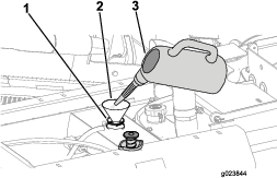
Remove the dipstick (Figure 91), and wipe it clean.
-
Insert the dipstick into the oil fill tube, pull the dipstick out again, and read the oil level on the dipstick.
Note: The oil level on the dipstick should be at the High mark or between the Low and High marks. If the oil is below the Low mark, complete the following procedure:
-
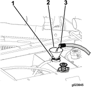
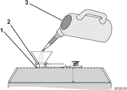
Remove the fill cap (Figure 92) and add oil until the level reaches the High mark. Do not overfill.
Important: Use an oil canister with a bendable hose or a funnel to fill the machine with oil.
-
Install the oil-fill cap and the dipstick.
-
Changing the Engine-Oil Filter
| Maintenance Service Interval | Maintenance Procedure |
|---|---|
| Every 250 hours |
|
-
Park the machine on a level surface, stop the engine, and remove the ignition key.
-
Open the front hood.
-
Align a drain pan or several rags under the oil filter and the oil-filter adapter (Figure 93).
-
Rotate the oil filter counterclockwise and remove the oil filter (Figure 93).
Note: Discard the oil filter.
-
Using a clean rag, wipe clean the surface of the oil-filter adapter where the oil filter seats with a clean rag.
-
Fill the new oil filter with the specified engine oil.
-
Apply a thin layer of the specified engine oil to the seal of the oil filter.
-
Align the oil filter to the oil-filter adapter, and rotate it clockwise until the seal of the oil filter contacts the oil-filter adapter (Figure 93).
Important: Do not use an oil filter strap wrench to install the new oil filter. The wrench can dent an oil filter and therefore cause a leak.
-
Hand tighten the oil filter an additional 1/2 turn (Figure 93).
-
Remove the oil pan or rags you placed in step 3 and dispose of the used oil according to local codes.
Changing the Engine Oil
| Maintenance Service Interval | Maintenance Procedure |
|---|---|
| Every 250 hours |
|
-
Park the machine on a level surface, stop the engine, and remove the ignition key.
Warning
Allow the engine and oil to cool before draining the oil. Hot oil may cause serious injury.
-
Ensure that the drain hose (Figure 94) is carefully pulled up and the end of the hose is placed in a drain pan.
-
Open the drain valve (Figure 94).
-
Drain the oil into the drain pan.
-
When the oil stops, close the drain valve (Figure 94).
-
Place the drain hose back into the original position (Figure 94).
-
Change the engine oil filter; refer to Changing the Engine-Oil Filter.
-
Remove the oil-fill cap from the filler neck by pulling the cap upward.
Note: Use a funnel with a flexible, attached hose to direct the engine oil into the engine.
-
Fill the crankcase with approximately 7.5 L (7.9 US qt) of the specified engine oil; refer to Servicing the Engine Oil and Filter.
-
Install the oil-fill cap.
-
Start the engine, run it at idle for about 2 minutes, and check for oil leaks.
-
Stop the engine and remove the key.
-
Wait for 2 or 3 minutes and check the oil level; refer to Checking the Engine-Oil Level.
Adjusting the Valve Clearance
| Maintenance Service Interval | Maintenance Procedure |
|---|---|
| After the first 250 hours |
|
| Every 2,000 hours |
|
Refer to the engine owner’s manual, which is included with the machine, for the adjustment procedure.
If you cannot adjust the valve clearance, contact your Authorized Toro Service Dealer.
Fuel System Maintenance
Danger
Under certain conditions, diesel fuel and fuel vapors are highly flammable and explosive. A fire or explosion from fuel can burn you and others and can cause property damage.
-
Use a funnel and fill the fuel tank outdoors, in an open area, when the engine is off and cold. Wipe up any fuel that spills.
-
Do not fill the fuel tank completely full. Add fuel to the fuel tank until the level is 25 mm (1 inch) below the bottom of the filler neck. This empty space in the tank allows the fuel to expand.
-
Never smoke when handling fuel, and stay away from an open flame or where fuel fumes may be ignited by a spark.
-
Store fuel in a clean, safety-approved container and keep the cap in place.
Draining Water from the Fuel Filter
| Maintenance Service Interval | Maintenance Procedure |
|---|---|
| Every 50 hours |
|
-
Park the machine on a level surface, stop the engine, and remove the ignition key.
-
Open the front hood.
-
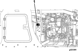
Align a drain pan under the primary fuel filter (Figure 96).
-
Rotate the drain valve at the bottom of the primary fuel filter 2 or 3 turns counterclockwise, and drain any water and sediment from the fuel filter (Figure 96).
Note: If the fuel-water separator has any water or sediment, also drain the water and sediment from the fuel tank; refer to Draining Water from the Fuel Tank.
-
When clean fuel appears, rotate the drain valve clockwise until it is closed.
Note: Do not overtighten the drain valve.
-
Prime the fuel system; refer to Priming the Fuel System.
Draining Water from the Fuel Tank
-
Park the machine on a level surface, stop the engine, and remove the ignition key.
-
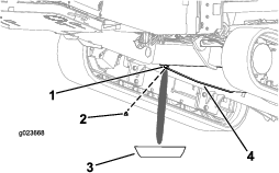
Place a drain pan under the drain plug in the fuel tank.
-
Loosen the drain plug until the water and sediment drain out (Figure 97).
-
Clean the threads on the drain plug and apply 3 layers of PTFE sealing tape.
-
Clean the O-ring if it comes out.
-
When clean fuel appears, install the O-ring and drain plug, and tighten the plug securely.
-
Check the fuel-tank drain plug for leaks.
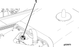
Priming the Fuel System
Note: Prime the fuel system whenever any of the following occurs:
-
You drained water from the fuel filter.
-
You replaced the fuel filter.
-
You ran the engine until the fuel tank is empty or drained the fuel tank.
-
Park the machine on a level surface, stop the engine, and remove the ignition key.
-
Open the front hood.
-
Ensure that the engine and the exhaust system are cool.
-
Ensure that the fuel tank is at least 1/4 full.
-
Rotate the BATTERY-DISCONNECT switch clockwise to the ON position.
-
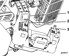
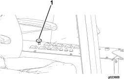
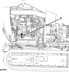
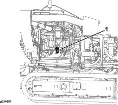
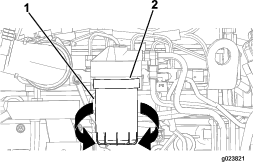
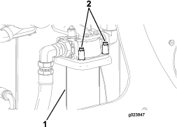
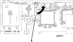
Locate the PRIMING button on the top of the filter adapter for the primary fuel filter (Figure 98).
-
Press down and release the PRIMING button repeatedly until you feel resistance when pressing the PRIMING button (Figure 98).
-
If the engine does not start after priming the fuel system and making several attempts to start the engine, bleed the high-pressure fuel lines; refer to your engine owner’s manual or contact your Authorized Toro Service Dealer.
Warning
The fuel system is under high pressure. Bleeding the system without proper precautions and training could result in injury to you from injected fluid or fire or explosion.
Read the engine owner’s manual for the proper bleeding procedure or contact your Authorized Toro Dealer.
Replacing the Fuel Filters
| Maintenance Service Interval | Maintenance Procedure |
|---|---|
| Every 250 hours |
|
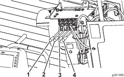
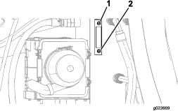
Replacing the Primary Fuel Filter
-
Park the machine on a level surface, stop the engine, and remove the ignition key.
-
Open the front hood; refer to Opening the Front Hood.
-
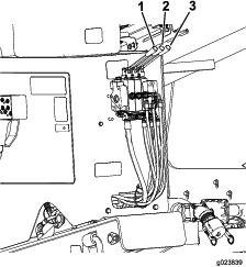
Place clean rags under the primary fuel filter (Figure 98).
-
Loosen the hose clamps and separate the primary fuel filter from the fuel hoses (Figure 98).
Note: Do not remove the hose clamps from the hoses.
Note: Discard the fuel filter.
-
Align the new primary fuel filter to the hoses with the arrow printed on the filter pointing forward.
-
Slip the hoses over the hose fitting of the primary fuel filter, and tighten the hose clamps (Figure 98).
-
Replace the secondary fuel filter; refer to Replacing the Secondary Fuel Filter.
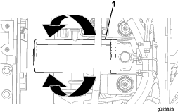
Replacing the Secondary Fuel Filter
-
Park the machine on a level surface, stop the engine, and remove the ignition key.
-
Open the front hood; refer to Opening the Front Hood.
-
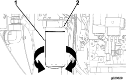
Align a drain pan or several rags under the secondary fuel filter and the fuel-filter adapter (Figure 99).
-
Rotate the fuel filter counterclockwise and remove the fuel filter (Figure 99).
Note: Discard the fuel filter.
-
Using a clean rag, wipe clean the surface of the fuel-filter adapter where the fuel filter seats with a clean rag.
-
Fill the new fuel filter with the specified fuel.
-
Align the fuel filter to the fuel-filter adapter, and rotate it clockwise until the seal of the fuel filter contacts the fuel-filter adapter (Figure 99).
Important: Do not use a fuel filter strap wrench to install the new oil filter. The wrench can dent a fuel filter and therefore cause a leak.
-
Hand tighten the fuel filter and additional 1/2 turn (Figure 99).
-
Remove the drain pan or rags you placed in step 3 and dispose of the used fuel according to local codes.
Checking the Fuel Lines and Connections
| Maintenance Service Interval | Maintenance Procedure |
|---|---|
| Every 500 hours |
|
Inspect the fuel lines and connections for deterioration, damage, or loose connections.
Draining and Cleaning the Fuel Tank
| Maintenance Service Interval | Maintenance Procedure |
|---|---|
| Every 1,000 hours |
|
Drain and clean the tank if the fuel system becomes contaminated or if the machine will be stored for an extended period of time. Use clean fuel to flush out the tank. Refer to Draining Water from the Fuel Tank for draining instructions.
Note: Perform this procedure when the fuel level is low, to avoid draining a large volume of fuel.
Electrical System Maintenance
Battery Safety
-
Turn off the battery-disconnect switch before repairing the machine.
-
Charge the battery in an open, well-ventilated area, away from sparks and flames. Unplug the charger before connecting or disconnecting the battery. Wear protective clothing and use insulated tools.
Servicing the Battery
| Maintenance Service Interval | Maintenance Procedure |
|---|---|
| Every 50 hours |
|
Important: Before welding on the machine, disconnect the negative cable from the battery to prevent damage to the electrical system. Also, disconnect the engine and machine controller before welding on the machine.
Note: Check the battery condition weekly or after every 50 hours of operation. Keep the terminals and the entire battery case clean because a dirty battery discharges slowly. To clean the battery, wash the entire case with a solution of baking soda and water. Rinse with clear water. Coat the battery posts and cable connectors with Grafo 112X (skin-over) grease (Toro Part No. 505-47) or petroleum jelly to prevent corrosion.
Warning
Exposure to battery acid or a battery explosion can cause serious personal injury.
Before you service a battery, wear face protection, protective gloves, and protective clothing.
Warning
A battery contains sulfuric acid, which can cause serious burns; and it can produce explosive gases.
-
Avoid contact with skin, eyes, or clothing; flush affected areas with water.
-
If taken internally, drink large quantities of water or milk. Do not induce vomiting. Seek medical attention immediately.
-
Keep sparks, flames, and lit cigarettes and cigars away from the battery.
-
Ventilate the battery when you are charging it or using it in an enclosed area.
-
Wear eye protection when working near a battery.
-
Wash your hands after handling a battery.
-
Keep the battery out of the reach of children.
Warning
If you try to charge or jump start a frozen battery, it could be explosive, causing personal injury to you or others in the area.
To prevent the battery electrolyte from freezing, keep the battery fully charged.
Warning
-
Sparks or a flame can cause hydrogen gas in a battery to explode.
-
When you disconnect the battery cables, disconnect the negative (-) cable first.
-
When you connect the battery cables, connect the negative (-) cable last.
-
Do not short-circuit the battery posts with a metal object.
-
Do not weld, grind, or smoke near a battery.
Note: The electrical system in this machine is 12 volts.
Charging the Battery
Warning
Charging the battery produces gasses that can explode.
Do not smoke near the battery, and keep sparks and flames away from the battery.
Important: Keep the battery fully charged. This is especially important to prevent battery damage when the temperature is below 32°F (0°C).
-
Park the machine on a level surface, stop the engine, and remove the ignition key.
-
Open the front hood.
-
Clean the exterior of the battery case and the battery posts.
Note: Connect the leads of the battery charger to battery posts before connecting the charger to the electrical source.
-
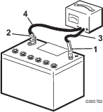
Look at the battery and identify the positive and negative battery posts.
-
Connect the positive lead of the battery charger to the positive battery post (Figure 100).
-
Connect the negative lead of the battery charger to the negative-battery post (Figure 100).
-
Connect the battery charger to the electrical source, and charge the battery according to the Battery-charging Table that follows.
Important: Do not overcharge the battery.
Battery-charger Table
Charger setting Charging time 4 to 6 amperes 30 minutes 25 to 30 amperes 10 to 15 minutes -
When the battery is fully charged, unplug the charger from the electrical source, then disconnect the charger leads from the battery posts (Figure 100).
Jump-Starting the Machine
Warning
Jump-starting the battery can produce gasses that can explode.
Do not smoke near the battery, and keep sparks and flames away from battery.
Note: This procedure requires 2 people to perform. Ensure that the person making the connections wears the proper face protection, protective gloves, and clothing.
-
Park the machine on a level surface, stop the engine, and remove the ignition key.
-
Open the front hood.
-
Ensure that all controls are in the NEUTRAL position.
-
Sit in the operator seat and have the other person make the connections.
Note: Ensure that the jumper battery is a 12-volt battery.
Important: If you are using another machine for power, ensure that the 2 machines are not touching each other.
-
Prepare to start the engine; refer to Starting and Stopping the Engine.
-
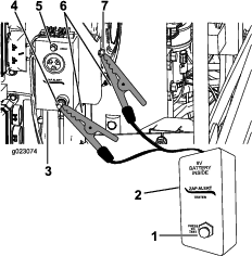
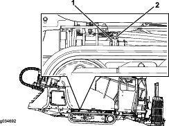
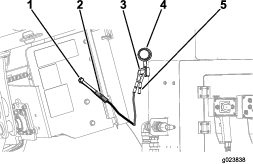
Remove the cover from the jump post (Figure 101).
-
Connect the positive (+) jumper cable to the jump post (Figure 101).
-
Connect the negative (-) jumper cable to a ground point, such as an unpainted bolt or chassis member (Figure 101).
-
Start the engine; refer to Starting and Stopping the Engine.
Important: If the engine starts and then stops, do not operate the starter motor until the starter motor stops turning. Do not operate the starter motor for more than 30 seconds at one time. Wait 30 seconds before operating the starter motor to cool the motor and to build up the charge in the battery.
-
When the engine starts, have the other person disconnect the negative (-) jumper cable from the frame and then disconnect the positive (+) jumper cable (Figure 101).
Drive System Maintenance
Checking the Oil Level for the Stakedown Planetary Drive
| Maintenance Service Interval | Maintenance Procedure |
|---|---|
| After the first 100 hours |
|
| Every 500 hours |
|
Oil specification: SAE 85W-140 API classification level GL4
Planetary-drive oil capacity: approximately 1.2 L (2.5 US pt)
Toro Premium Gear Oil is available from an Authorized Toro Service Dealer. See the parts catalog for part numbers.
-
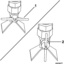
Check the oil level on the sight-glass on each stakedown planetary drive (Figure 102).
Note: The oil level should cover half of the sight-glass.
-
Remove the breather cap and add the oil into the planetary drive until the oil level on the sight-glass is at least half full (Figure 102).
-
Repeat for the other stakedown planetary.
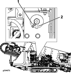
Checking the Oil Level for the Tracks Planetary Drive
| Maintenance Service Interval | Maintenance Procedure |
|---|---|
| Every 50 hours |
|
Oil specification: SAE 85W-140 API classification level GL4
Planetary-drive oil capacity: approximately 1.4 L (1.5 US pt)
Toro Premium Gear Oil is available from an Authorized Toro Service Dealer. See the parts catalog for part numbers.
-
Park the machine on a level surface, stop the engine, and remove the ignition key.
-
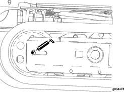
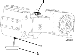
Clean the area around the oil-level plug with a cleaning solvent (Figure 103).
-
Remove the oil-level plug (Figure 103).
Note: The oil level is correct when it is up to the bottom of the oil-level plug hole.
-
If the oil is below the bottom of the hole, add the specified oil until the oil is level with the bottom of the hole.
-
Install and tighten the oil-level plug.
Changing the Oil for the Tracks Planetary Drive
| Maintenance Service Interval | Maintenance Procedure |
|---|---|
| After the first 250 hours |
|
| Every 800 hours |
|
Note: Change the oil when it is warm, if possible.
-
Park the machine on a level surface.
-
Clean the area around the oil-level plug (Figure 103).
-
Rotate the planetary drive until the oil-drain plug is directly below the oil-level plug (Figure 103).
-
Stop the engine and remove the key.
-
Place a drain pan under the oil-drain plug.
-
Remove the oil-level plug and the oil-drain plug.
-
Install the oil-drain plug.
-
Fill the chain drive planetary with oil until the oil is even with the bottom of the oil-level plug hole.
-
Install the oil-level plug.
-
Repeat steps 1 through 9 to change the planetary-drive oil on the other side of the machine.
Checking the Oil Level for the Rotary Motor Planetary Drive
| Maintenance Service Interval | Maintenance Procedure |
|---|---|
| After the first 100 hours |
|
| Every 500 hours |
|
Oil specification: SAE 85W-140 API classification level GL4
Planetary-drive oil capacity: approximately 0.24 L (0.5 US pt)
Toro Premium Gear Oil is available from an Authorized Toro Service Dealer. See the parts catalog for part numbers.
-
Park the machine on a level surface, stop the engine, and remove the ignition key.
-
Check the oil level on the sight-glass on the rotary motor planetary drive (Figure 104).
Note: The oil level should be 3/4 full in the sight-glass.
-
If the oil level is low, remove the oil-level plug (Figure 104).
-
Install and tighten the oil-level plug.
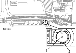
Checking the Oil for the Thrust Motor Planetary Drive
| Maintenance Service Interval | Maintenance Procedure |
|---|---|
| After the first 100 hours |
|
| Every 500 hours |
|
Oil specification: SAE 85W-140 API classification level GL4
Planetary-drive oil capacity: approximately 0.24 L (0.5 US pt)
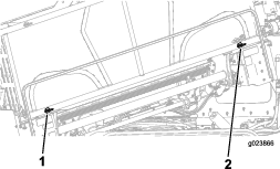
-
Park the machine on a level surface, stop the engine, and remove the ignition key.
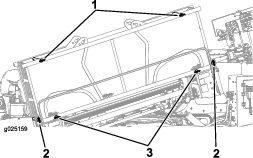
-
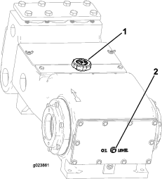
Check the oil level on the sight-glass on each thrust motor planetary drive (Figure 106).
Note: The oil level should cover half of the sight-glass.
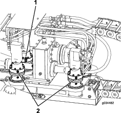
-
Remove the breather cap and add the oil into the planetary drive until the oil level on the sight-glass is at least half full (Figure 106).
-
Repeat for all 4 thrust motor planetary drives.
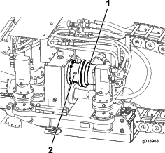
Checking the Oil for the Gearbox Drive
| Maintenance Service Interval | Maintenance Procedure |
|---|---|
| After the first 100 hours |
|
| Every 500 hours |
|
Oil specification: SAE 85W-140 API classification level GL4
Planetary-drive oil capacity: approximately 2.7 L (5.75 US pt)
-
Park the machine on a level surface, stop the engine, and remove the ignition key.
-
Check the oil level on the sight-glass on the gearbox drive (Figure 106).
Note: The oil level should cover half of the sight-glass.
-
Remove the breather cap and add the oil into the gearbox drive until the oil level on the sight-glass is at least half full (Figure 106).
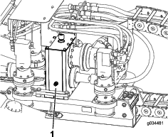
Changing the Oil for the Gearbox Drive
| Maintenance Service Interval | Maintenance Procedure |
|---|---|
| After the first 100 hours |
|
| Every 500 hours |
|
Note: Change the oil when it is warm, if possible.
-
Park the machine on a level surface and move the carriage all the way to the rear stop.
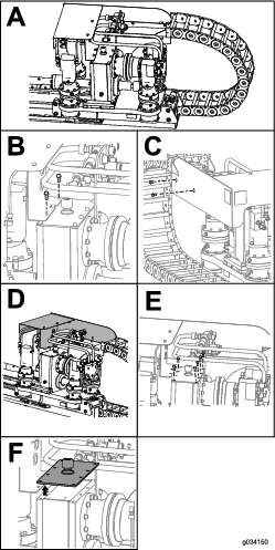
-
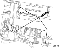
Stop the engine and remove the ignition key.
-
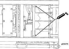
Remove the 2 bolts and nuts on the carriage guard (Box B of Figure 107).
-
Remove the 2 bolts and nuts on the side of the carriage guard (Box C of Figure 107).
-
Slide the carriage guard forward (Box D of Figure 107).
-
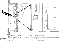
Remove the 6 bolts on the gearbox (Box E of Figure 107).
-
Remove the cover on the gearbox and syphon the oil out (Box F of Figure 107).
-
Fill the gearbox with oil until the oil level in the sight glass is more than half full (Figure 106).
-
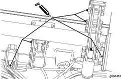
Clean the sealant off of the gearbox box and cover (Figure 108).
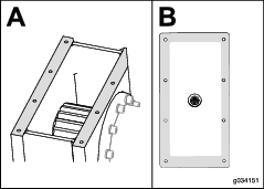
-
Put new automotive-grade RTV sealant around the edge of the cover (Box B of Figure 108).
-
Slide the cover back onto the gearbox and loosely install the 6 bolts (Box E of Figure 107).
-
Place the carriage guard back into place and loosely install the 2 bolts (Box C of Figure 107).
-
Install the 2 bolts securing the carriage guard onto the gearbox (Box B of Figure 107).
-
Tighten the 6 bolts on the gearbox and the 2 bolts on the side of the carriage guard.
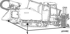
Servicing the Tracks
| Maintenance Service Interval | Maintenance Procedure |
|---|---|
| Before each use or daily |
|
Warning
Grease in the hydraulic track is highly pressurized; ensure that the track-tension grease valve is not loosened more than 1 revolution at a time.
If you remove the track-tension grease valve (found in the hydraulic-track tensioner) or loosen it too much, grease can be released and may cause serious injury or death.
Tightening the Track Tension
If the track seems loose, tighten the track tension as follows:
-
Park the machine on a level surface, stop the engine, and remove the ignition key.
-
Remove dirt and debris found around the track-tension grease valve (Figure 109).
Important: Ensure that the area surrounding the track-tension grease valve is clean before beginning to adjust the track tension.
-
Remove the retaining bolts and cover that house the track-tension grease valve.
-
Apply grease to the fitting until the tension reaches 31,026 kPa (4,500 psi) as shown in Figure 109.
-
Remove excess grease from around the valve.
-
Install the cover and retaining bolts.
-
Repeat steps 2 through 6 to tighten the track tension on the other side.
Loosening the Track Tension
If the track seems tight, loosen the track tension as follows:
-
Park the machine on a level surface, stop the engine, and remove the ignition key.
-
Remove dirt and debris found around the track-tension grease valve (Figure 109).
Important: Ensure that the entire area surrounding the track-tension grease valve is clean before beginning to adjust the track tension.
-
Remove the retaining bolts and the cover that house the track-tension grease valve.
-
Turn the track-tension grease valve counterclockwise no more than 1 revolution (Figure 109).
Note: A 1-revolution turn will release grease and loosen the track.
-
When the tension reaches 31,026 kPa (4,500 psi), turn the track-tension grease valve clockwise to tighten it.
-
Remove excess grease from around the valve.
-
Install the cover and retaining bolts.
-
Repeat steps 2 through 7 to loosen the track tension on the other side.
Cooling System Maintenance
Coolant specification: 50/50 solution of ethylene-glycol antifreeze and water or equivalent
Engine and Radiator coolant capacity: 16.8 L (17.7 US qt)
Warning
If you remove the radiator cap from a hot engine, hot coolant could spray, causing scalding.
-
Wear face protection when opening the radiator cap.
-
Allow the cooling system to cool down to below 50°C (120°F) before removing the radiator cap.
-
Follow the instructions for checking and maintaining the engine cooling system.
Warning
Coolant is toxic.
-
Keep coolant away from children and pets.
-
If you are not using the same coolant again, dispose of it according to local environmental regulations.
Cooling System Safety
-
Swallowing engine coolant can cause poisoning; keep it out of reach of children and pets.
-
Discharge of hot, pressurized coolant or touching a hot radiator and surrounding parts can cause severe burns.
-
Always allow the engine to cool at least 15 minutes before removing the radiator cap.
-
Use a rag when opening the radiator cap, and open the cap slowly to allow steam to escape.
-
Checking the Coolant Level in the Radiator
| Maintenance Service Interval | Maintenance Procedure |
|---|---|
| Before each use or daily |
|
Warning
If the engine has been running, the radiator will be pressurized and the coolant inside will be hot. If you remove the cap, coolant may spray out, causing severe burns.
Do not remove the radiator cap when the engine is hot. Allow the engine to cool for at least 15 minutes or until the radiator cap is cool enough to touch without burning your hand.
Note: The cooling system is filled with a 50/50 solution of water and ethylene-glycol antifreeze.
-
Park the machine on a level surface, stop the engine, and remove the ignition key.
-
Allow the engine to cool.
-
Open the rear-access door.
-
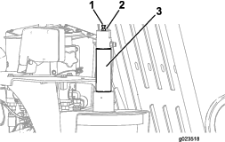
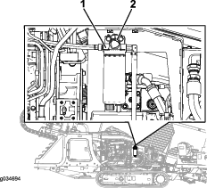
Check the coolant level by looking at the sight gauge at the end of the radiator tank (Figure 110).
-
If the coolant level is low, add coolant until the level is up to the bottom of the filler neck; refer to Filling the System with Coolant.
Important: Do not overfill the radiator.
-
If the coolant level is normal, close the rear-access door.
-
Checking the Condition of Cooling-System Components
| Maintenance Service Interval | Maintenance Procedure |
|---|---|
| Every 300 hours |
|
Check the condition of the cooling system for leaks, damage, dirt, and loose hoses and clamps. Clean, repair, tighten, and replace the components as necessary.
Checking the Concentration of the Coolant
| Maintenance Service Interval | Maintenance Procedure |
|---|---|
| Every 1,000 hours |
|
Test the concentration of ethylene glycol-based antifreeze in the coolant. Ensure that the coolant has a 50% ethylene glycol and 50% water mixture or equivalent.
Note: A 50% ethylene glycol and 50% water mixture will protect the engine to -37° C (-34° F) throughout the year.
Using a concentration tester, check the concentration of the coolant mixture to ensure that it is 50% ethylene glycol and 50% water or equivalent; refer to the manufacturer’s instructions for testing.
Cleaning the Cooling System
| Maintenance Service Interval | Maintenance Procedure |
|---|---|
| Every 1,000 hours |
|
Draining the Coolant from the System
Important: Do not pour coolant onto the ground or into an unapproved container that can leak.
-
Park the machine on a level surface, stop the engine, and remove the ignition key.
-
Allow the engine to cool.
-
Open the rear-access door.
Note: Look to the left when you open the rear-access door, and you will find the drain plug tucked away in the back-left corner.
-
Place a drain pan under the drain plug (Figure 111).
Note: The coolant capacity of both the engine and the radiator is 16.8 L (17.7 US qt).
-
Open the drain plug for the radiator and allow the coolant system to drain completely.
Note: Dispose of the used coolant properly according to local codes.
-
Clean the threads on the drain plug and apply 3 layers of PTFE sealing tape.
-
Close the drain plug (Figure 111).
Flushing the Cooling System
Engine and radiator coolant capacity: 16.8 L (17.7 US qt)
-
Park the machine on a level surface, stop the engine, and remove the ignition key.
-
Condition the cooling system as follows:
-
Ensure that the coolant is drained from the radiator and that the drain plug is closed; refer to Draining the Coolant from the System.
-
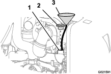
Add a cooling system cleaning solution to the to the radiator through the filler neck (Figure 112).
Note: Use cleaning solution of 21 g (12 oz dry) of sodium carbonate for every 17 L (18 US qt) of water; otherwise, use a commercially available equivalent. Follow the directions that come with the cleaning solution.
-
Close the drain plug (Figure 111).
Important: Do not install the radiator cap.
-
Operate the engine for 5 minutes or until the coolant temperature indicates 82° C (180° F), and then stop the engine.
Caution
The cleaning solution is hot and can cause burns.
Stay away from the discharge end of the coolant drain plug.
-
Open the drain plug for the radiator, and drain the cleaning solution into a drain pan.
-
Clean the threads on the drain plug and apply 3 layers of PTFE sealing tape.
-
Close the drain plug.
-
-
Flush the cooling system as follows:
-
Open the filler-neck cap.
-
Fill the radiator with clean water (Figure 113).
-
Close the filler-neck cap.
-
Operate the engine for 5 minutes or until the coolant temperature indicates 82°C (180°F), and then stop the engine.
Caution
The water is hot and can cause burns.
Stay away from the discharge end of the coolant drain plug.
-
Open the drain plug and drain the water into a drain pan.
-
Clean the threads on the drain plug and apply 3 layers of PTFE sealing tape.
-
If the water drained from the radiator is dirty, perform steps 3-1 through 3-5 until the water drained from the radiator is clean.
-
Close the drain plug (Figure 111).
-
Filling the System with Coolant
Important: You must fill the cooling system properly to prevent air locks in the cooling passages. Failing to vent the cooling system properly can severely damage the cooling system and engine.
Important: Use a mixture of 50% ethylene glycol and 50% water mixture or equivalent in the machine. The lowest ambient operating temperature for this mixture is above -37° C (-34° F). If the ambient temperature is lower, adjust the mixture. Use a mixture of ethylene glycol and water or equivalent in the machine all year.
-
Park the machine on a level surface, stop the engine, and remove the ignition key.
-
Remove the bolts from the coolant-access cover between the front hood and the rear cover.
-
Remove the radiator cap (Figure 115).
-
Fill the radiator with coolant until the fluid level is up to the bottom of the filler neck (Figure 116).
Note: The coolant capacity of both the engine and the radiator is 16.8 L (17.7 US qt).
-
Install the radiator filler cap, ensuring that it is tightly sealed (Figure 115).
-
Start the engine and run it at half throttle for 5 minutes.
-
Stop the engine and remove the key.
-
Wait 30 minutes, then check the fluid level in the radiator sight gauge; refer to Checking the Coolant Level in the Radiator.
Note: If it is low, add coolant.
Belt Maintenance
Servicing the Engine-Drive Belt
Warning
Contacting a rotating belt can cause serious injury or death.
Stop the engine and remove the ignition key before working near belts.
Checking the Condition of the Belt
| Maintenance Service Interval | Maintenance Procedure |
|---|---|
| Every 250 hours |
|
-
Park the machine on a level surface, stop the engine, and remove the ignition key.
-
Open the front hood.
-
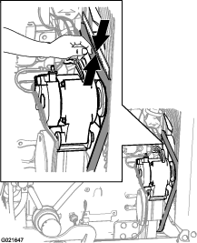
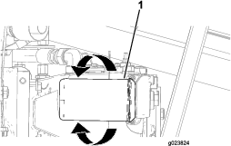
Inspect the belt for cuts, cracks, loose cords, grease, oil, twisting, or signs of abnormal wear (Figure 117).
Note: Replace the belt if it is excessively worn or damaged.
Checking the Tension of the Belt
| Maintenance Service Interval | Maintenance Procedure |
|---|---|
| Every 1,000 hours |
|
-
Park the machine on a level surface, stop the engine, and remove the ignition key.
-
Open the front hood.
-
Align a straight edge over the drive belt and across the pulleys as shown in Figure 117.
-
Press the belt down at the midway point between the fan pulley and the alternator pulley as shown in Figure 117.
Note: The range of belt deflection between the straight edge and the belt should be 7 to 9 mm (9/32 to 11/32 in), under a load of 10 kg (22 lb).
-
If the tension of the belt is above or below the specified range, adjust the drive belt tension; refer to Adjusting the Tension of the Belt.
Adjusting the Tension of the Belt
-
Park the machine on a level surface, stop the engine, and remove the ignition key.
-
Open the front hood.
-
Loosen the nut and bolt at the pivot point for the alternator (Figure 118).
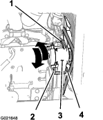
-
Loosen the adjustment bolt on the alternator (Figure 118).
-
Move the alternator away from the engine to increase the belt tension; move the alternator toward the engine to decrease the belt tension (Figure 118).
-
Tighten the alternator adjustment bolt (Figure 118).
-
Check the tension of the belt; refer to Checking the Tension of the Belt.
-
If the belt tension is correct, tighten the nut and bolt at the pivot point for the alternator (Figure 118); otherwise, repeat steps 4 through 7.
Hydraulic System Maintenance
Hydraulic System Safety
-
Seek immediate medical attention if fluid is injected into skin. Injected fluid must be surgically removed within a few hours by a doctor.
-
Ensure that all hydraulic-fluid hoses and lines are in good condition and all hydraulic connections and fittings are tight before applying pressure to the hydraulic system.
-
Keep your body and hands away from pinhole leaks or nozzles that eject high-pressure hydraulic fluid.
-
Use cardboard or paper to find hydraulic leaks.
-
Safely relieve all pressure in the hydraulic system before performing any work on the hydraulic system.
Servicing the Hydraulic Fluid
The hydraulic reservoir is filled at the factory with approximately 170 L (45 US gallons) of high-quality hydraulic fluid. Check the level of the hydraulic fluid before the engine is first started and daily thereafter. The recommended replacement fluid as follows:
Toro Premium All Season Hydraulic Fluid (Available in 5 gallon pails or 55 gallon drums. Contact your Authorized Toro Dealer for part numbers.)
Alternate fluids: If the Toro fluid is not available, other fluids may be used provided they meet all the following material properties and industry specifications. We do not recommend the use of synthetic fluid. Consult with your lubricant dealer to identify a satisfactory product.
Note: Toro will not assume responsibility for damage caused by improper substitutions, so use only products from reputable manufacturers who will stand behind their recommendation.
| Material Properties: | ||
| Viscosity, ASTM D445 | 42.2 cSt at 40° C (104° F) | |
| 7.8 cSt at 100° C (212° F) | ||
| Viscosity Index ASTM D2270 | 158 | |
| Pour Point, ASTM D97 | -6° C (-42° F) | |
| Industry Specifications: | Vickers I-286-S (Quality Level), Vickers M-2950-S (Quality Level), Denison HF-0 | |
Note: Many hydraulic fluids are almost colorless, making it difficult to spot leaks. A red dye additive for the hydraulic system oil is available in 20 mL (2/3 oz) bottles. One bottle is sufficient for 15-22 L (4-6 gal) of hydraulic oil. Order hydraulic oil from your Authorized Toro Dealer.
Note: If ambient operating temperatures exceed 43° C (110° F), contact Toro for fluid recommendations.
Checking the Hydraulic Fluid
| Maintenance Service Interval | Maintenance Procedure |
|---|---|
| Before each use or daily |
|
Check the hydraulic fluid as follows:
-
Park the machine on a level surface, stop the engine, and remove the ignition key.
-
Wait 10 minutes to allow the engine to cool and the hydraulic oil to stabilize.
-
Open the rear-access door.
-
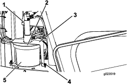
Look at the sight gauge on the hydraulic tank and check the level of the oil (Figure 119).
-
If the level is low, open the hydraulic-tank cap (Figure 120), add a small amount of oil and wait 2 minutes for the oil level to stabilize in the sight gauge (Figure 119).
Note: The oil level is between 1/2 to 2/3 full in the sight gauge when the oil is at ambient temperature or if the engine has not yet been started for the day.
-
Continue to add the appropriate fluid in small increments until it reaches Full on the sight gauge.
-
Install cap onto the filler neck.
Changing the Hydraulic Fluid
| Maintenance Service Interval | Maintenance Procedure |
|---|---|
| Every 1,000 hours |
|
Important: If the fluid becomes contaminated, contact your Authorized Toro Dealer, because the system must be flushed. Contaminated fluid looks milky or black when compared to clean oil.
Important: Use of any other filter may void the warranty on some components.
-
Park the machine on a level surface, stop the engine, and remove the ignition key.
-
Open the rear-access door.
-
Raise the machine using proper equipment.
Warning
Raising the unit relying solely on mechanical or hydraulic jacks could be dangerous. The mechanical or hydraulic jacks may not be enough support or may malfunction allowing the unit to fall, which could cause injury or death.
Do not rely solely on mechanical or hydraulic jacks for support.
Use adequate jack stands or equivalent support.
-
Place a large draining container under the hydraulic fluid tank.
-
Remove the drain plug from the bottom of the tank.
-
Clean the threads on the drain plug and apply 3 layers of PTFE sealing tape.
-
Drain the hydraulic fluid flow into the container.
Important: The capacity of the hydraulic-fluid tank is 170 L (45 US gal), so ensure that you have a container of at least 182 L (48 US gal) to drain the fluid into.
-
Install the drain plug when the hydraulic fluid stops draining.
-
Fill the reservoir with hydraulic fluid.
Important: Use only the hydraulic fluids specified. Other fluids could cause system damage.
-
Install the reservoir cap.
-
Start the engine and use all of the hydraulic controls to distribute hydraulic fluid throughout the system.
-
Check for leaks, then stop the engine.
-
Check the fluid level and add enough to raise level the level to the Full mark on the dipstick.
Note: Do not overfill.
Changing the Hydrostatic-Charge Filter
| Maintenance Service Interval | Maintenance Procedure |
|---|---|
| Every 500 hours |
|
-
Park the machine on a level surface, stop the engine, and remove the ignition key.
-
Open the front hood.
-
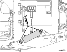
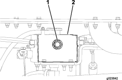
Align a drain pan or several rags under the hydrostatic-charge filter (Figure 121).
-
Rotate the hydrostatic-charge filter counterclockwise and remove the filter (Figure 121).
Note: Discard the hydrostatic-charge filter.
-
Using a clean rag, wipe clean the surface where the hydrostatic-charge filter seats with a clean rag.
-
Align the hydrostatic-charge filter to where it seats, and rotate it clockwise until the seal of the filter contacts the adapter (Figure 121).
Changing the High-Pressure Hydraulic Filter
| Maintenance Service Interval | Maintenance Procedure |
|---|---|
| Every 1,000 hours |
|
Warning
Ensure that the engine is in the OFF position before removing the high-pressure hydraulic filter. The high-pressure hydraulic filter contains very high pressure that could cause serious injury, or cause damage to the machine if released while the engine is running.
-
Park the machine on a level surface, stop the engine, and remove the ignition key.
-
Open the front hood.
-
Align a drain pan or several rags under the charge filter (Figure 122).
-
Rotate the high-pressure hydraulic filter counterclockwise and remove the filter (Figure 122).
-
Using a clean rag, wipe clean the surface where the high-pressure hydraulic filter seats with a clean rag.
-
Align the high-pressure hydraulic filter to where it seats, and rotate it clockwise until the torque reaches 61 N-m (45 ft-lb) as shown in Figure 122.
Changing the Hydraulic-Return Filter
| Maintenance Service Interval | Maintenance Procedure |
|---|---|
| Every 1,000 hours |
|
-
Park the machine on a level surface, stop the engine, and remove the ignition key.
-
Open the rear-access door.
-
Align a drain pan or several rags under the charge filter (Figure 123).
-
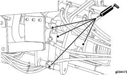
With one hand under the hydraulic-return filter, remove the 4 bolts as shown in Figure 123.
Note: There are 2 other bolts on the back side that need to be removed.
-
Pull down and remove the filter.
-
Using a clean rag, wipe clean the surface where the hydraulic-return filter seats with a clean rag.
-
Align the new hydraulic return filter to where it seats, and tighten the 4 bolts (Figure 123).
Checking the Hydraulic Lines and Hoses
| Maintenance Service Interval | Maintenance Procedure |
|---|---|
| Every 2 years |
|
Inspect the hydraulic lines and hoses daily for leaks, kinked lines, loose mounting supports, wear, loose fittings, weather deterioration, and chemical deterioration. Make all necessary repairs before operating.
Warning
Hydraulic fluid escaping under pressure can penetrate skin and cause injury.
-
Make sure that all hydraulic fluid hoses and lines are in good condition and all hydraulic connections and fittings are tight before applying pressure to the hydraulic system.
-
Keep your body and hands away from pin hole leaks or nozzles that eject high-pressure hydraulic fluid.
-
Use cardboard or paper to find hydraulic leaks.
-
Safely relieve all pressure in the hydraulic system before performing any work on the hydraulic system.
-
Seek immediate medical attention if fluid is injected into skin.
Checking the Hydraulic System Test Ports
The test ports are used to test the pressure in the hydraulic circuits. Contact your Authorized Toro Dealer for assistance.
Drilling-Fluid Pump Maintenance
Servicing the Drilling-Fluid-Pump Oil
The drilling-fluid pump is shipped with oil in the crankcase; however, check the oil level before and after you first start the engine.
The crankcase capacity is 3.8 L (4 US qt).
Use only high-quality engine oil that meets the following specifications:
-
API Classification Level Required: CH-4, CI-4 or higher
-
Oil:SAE 80W-90, non-detergent oil above 0° C (32° F)
Toro Premium Engine Oil is available from your dealer. See the parts catalog for part numbers. Also, refer to the Engine Operator's Manual, included with the machine, for further recommendations.
Checking the Drilling-Fluid-Pump Oil Level
| Maintenance Service Interval | Maintenance Procedure |
|---|---|
| Before each use or daily |
|
-
Park the machine on a level surface, stop the engine, and remove the ignition key.
-
Remove the oil-level plug on the crankcase (Figure 124).
-
If oil drains from the oil-level hole, insert the oil-level plug.
Note: The oil level is sufficient if oil drains from the opening, or is at least at the level of the oil-level plug.
-
If oil does not drain from the oil-level, or is not at the level of the oil-level plug, insert the oil-level plug, and open the oil-filler cap to add the specified oil.
-
-
Ensure that the oil is at the oil-fill line as shown in Figure 124.
Note: If the oil is below the oil-fill line, refer to step 8 of Changing the Drilling-Fluid-Pump Oil and add the necessary amount of oil.
Changing the Drilling-Fluid-Pump Oil
| Maintenance Service Interval | Maintenance Procedure |
|---|---|
| Every 500 hours |
|
-
Park the machine on a level surface, stop the engine, and remove the ignition key.
-
Allow the engine to cool.
-
Lower the thrust frame, and ensure that the cylinder lock is installed; refer to Using the Cylinder Lock.
-
Remove the drain plug and place a drain pan under the drain-plug hole (Figure 125).
-
Clean the threads on the drain plug and apply 3 layers of PTFE sealing tape.
-
Allow all of the oil to drain from drain plug into the oil pan (Figure 125).
-
Install the drain plug.
-
Remove the oil-filler cap (Figure 125) and add approximately 1.8 L (4 US qt) of oil, or until the oil reaches the level of the oil-level plug as shown in Figure 124.
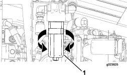
Changing the Drilling-Fluid-Pump, Charge Filter
-
Park the machine on a level surface, stop the engine, and remove the ignition key.
-
Open the front hood.
-
Align a drain pan or several rags under the charge filter (Figure 126).
-
Rotate the charge filter counterclockwise and remove the filter (Figure 126).
Note: Discard the charge filter.
-
Using a clean rag, wipe clean the surface where the charge filter seats with a clean rag.
-
Align the charge filter to where it seats, and rotate it clockwise until the seal of the filter contacts the adapter (Figure 126).
Preparing the Drilling-Fluid System for Cold Weather
Prepare the machine as follows after drilling if the temperature will be below 0° C (32° F).
-
Park the machine on a level surface, stop the engine, and remove the ignition key.
-
Prepare the machine to circulate the antifreeze as follows:
-
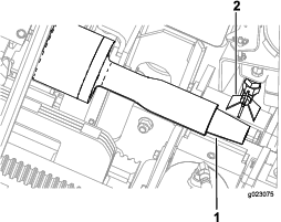
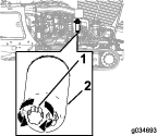
Place a drain pan under the drill spindle for the leaked antifreeze (Figure 127).
-
Ensure that the cap is installed on the drilling-fluid pump inlet (Figure 128).
-
Remove the cap from the antifreeze tank for the drilling-fluid pump (Figure 129).
-
Ensure that the tank is full of antifreeze (Figure 129).
-
-
Circulate the antifreeze as follows:
-
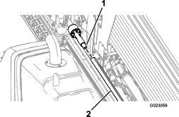
Open the antifreeze valve inside of the rear compartment (Figure 130).
-
Open the valve near the rear compartment (Figure 131).
-
Start the machine and turn On the drilling-fluid pump.
-
Add antifreeze to the tank as needed (Figure 129).
-
When the antifreeze comes out of the drill spindle (Figure 127), turn the pump off.
-
-
Turn the machine off.
-
Install the cap onto the antifreeze tank (Figure 129).
-
Close the antifreeze valve (Figure 130).
Cab Maintenance
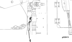
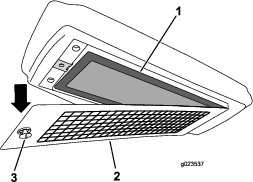
Changing the Cab Air Filter
-
Open the cab door; refer to Opening the Door (Model with Cab only).
-
Park the machine on a level surface, stop the engine, and remove the ignition key.
-
Remove the screw and the cover that house the air filter (Figure 132).
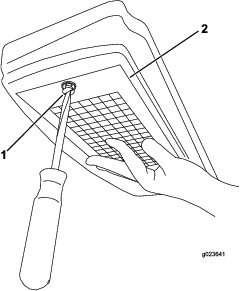
-
Remove the air filter from the housing, and replace the filter element (Figure 133).
Filling the Windshield-Washer Fluid Tank
-
Open the cab door; refer to Opening the Door (Model with Cab only).
-
Open the cap of the windshield-washer-fluid tank (Figure 134).
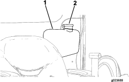
-
Fill the windshield-washer-fluid tank until it is full (Figure 134).
-
Close the windshield-washer-fluid-tank cap (Figure 134).
Cleaning
Cleaning with the Spray-Hose Attachment
| Maintenance Service Interval | Maintenance Procedure |
|---|---|
| Before each use or daily |
|
The machine comes with a spray-hose attachment that you can use to clean the machine and pipes.
Important: Do not spray any electronic component of the machine and ensure that the hood is down before cleaning the machine with the spray-hose attachment.
Important: If the outside temperature is below freezing, refer to Preparing the Drilling-Fluid System for Cold Weather before cleaning the machine.
To use the spray-hose attachment, perform the following procedure:
-
Park the machine on a level surface.
-
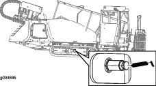
Using the right joystick, turn the drilling-fluid pump to the OFF position; refer to the Right Joystick.
-
Ensure that there is a clean water source to attach to the drilling-fluid pump.
-
Ensure that the valve near the rear compartment is in the CLOSED position (Figure 135).
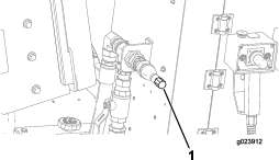
-
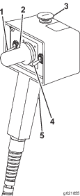
Connect the spray-hose attachment to the fitting (Figure 136).
-
Using the right joystick, turn the drilling-fluid pump to the ON position.
-
Adjust the drilling-fluid flow rate using the toggle switch to change the desired water pressure.
Note: Refer to Right Joystick or Right Joystick to increase or decrease the drilling-fluid flow rate.
-
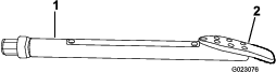
Using the spray-hose attachment, hold down the lever and spray down the machine and pipes.
Cleaning Plastic and Resin Parts
Avoid using gasoline, kerosene, paint thinner, etc., when cleaning plastic windows, the console, the instrument cluster, the monitor, gauges, etc. Use only water, mild soap, and a soft cloth when you clean these parts.
Using gasoline, kerosene, paint thinner, etc., to clean a plastic or resin part will cause it to discolor, crack, or deform.