Note: Determine the left and right sides of the machine from the normal
operating position.
Preparing the Machine
-
Park the machine on a level surface.
-
Shut off the cutting units.
-
Lower the cutting units.
-
Engage the parking brake, shut off the engine, remove
the key, and wait for all movement to stop before leaving the operator’s
seat.
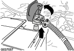
Disconnecting the Battery
-
Open the hood; refer to the Operator’s Manual
for your machine.
-
Lift the cover of the of the negative battery cable
(Figure 1).
Note: Lifting the cover loosens the battery cable clamp.
-
Remove the negative battery cable from the battery
(Figure 1).
Note: Position the negative-battery cable where it cannot contact
the negative battery post.
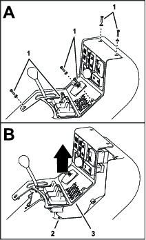
Accessing the Console
-
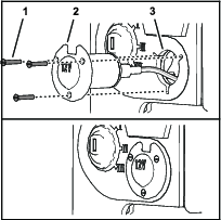
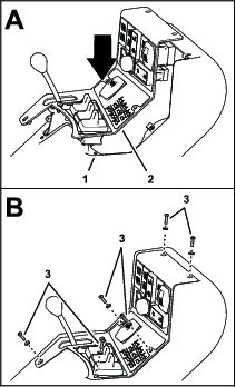
Remove the 6 screws and 6 washers that secure the
control panel to the console (Figure 2).
-
Lift the panel enough to provide access to the interior
of the console (Figure 2).
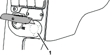
Installing the Accessory Port
Parts needed for this procedure:
| Accessory-port bracket | 1 |
| Accessory port | 1 |
| Countersunk-head screws (3 x 20 mm) | 3 |
-
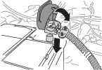
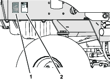
Cut a hole in the decal at the rear of the console
arm (Figure 3).
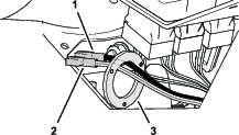
-
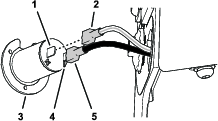
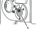
Working inside the console, locate the unused socket-terminal
connectors for the white/red wire and the black wire, and assemble
the accessory-port bracket over the wires (Figure 4).
-
Route the connectors and wires through the hole in
the console arm (Figure 5).
-
Connect the terminal for the black wire to the (-)
spade connector of the accessory port (Figure 5).
-
Connect the terminal for the white/red wire to the
(+) spade connector of the accessory port (Figure 5).
-
Assemble the accessory into the hole in the console
(Figure 6).
-
Working inside the console, assemble the accessory-port
bracket over the accessory port, and align the holes in the port and
bracket with the slots in the console arm.
-
Secure the port to the console and bracket (Figure 6) with the
3 countersunk-head screws (3 x 20 mm).
Installing the Fuse
-
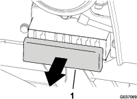
Remove the cover from the fuse block (Figure 7).
-
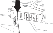
Insert the fuse (15 A) into the 2nd slot from the
left side of the fuse block (Figure 8).
-
Install the cover on to the fuse block (Figure 7).
Connecting the Negative Battery Cable
-
Assemble the negative battery cable onto the negative
battery post (Figure 9).
-
Align the insulator cover of the battery-cable terminal
and close the cover (Figure 9).
Note: Closing the cover tightens the battery cable clamp.
-
Plug the cord of a low-power device into the socket
of the accessory port. Ensure that the port supplies 12 VDC to an
attached device.
Note: If the accessory port does not supply 12 VDC, check the fuse
and electrical connections.
Completing the Accessory Port Installation
Parts needed for this procedure:
Installing the Control Panel
-
Align the holes in the control panel with the holes
in the console (Figure 10).
-
Assemble the control panel to the console (Figure 10) with the
6 screws and 6 washers that you removed in Accessing the Console.
Closing the Hood
Close and latch the hood.
Affixing the Serial Label
-
Clean the surface adjacent to the serial decal for
the machine (Figure 11).
-
Remove the backing from the serial decal from the
accessory-port kit.
-
Affix the serial decal to the surface adjacent to
the serial plate for the machine (Figure 11).