Removing the Cutting Unit from the Traction Unit
-
Position the machine on a level surface, raise the
cutting unit, engage the parking brake, ensure that the traction pedal
is in the neutral position and the PTO lever in the OFF position, shut off the engine, and remove the key from the switch.
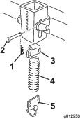
Caution
The counterbalance spring is in tension when the deck is in
the lower position (200 Series traction units only).
Always raise the deck before adjusting or removing the spring.
-
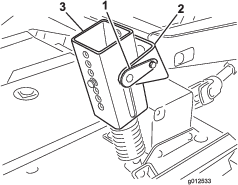
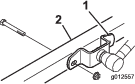
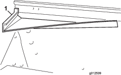
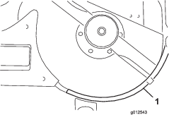
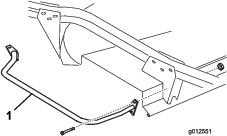
On 200 Series traction units only, disconnect the
counterbalance from the traction unit, remove the lock pins from the
brackets, separate the spring tension assemblies from the brackets,
and lay them down on the deck. Loosely secure the lock pins to the
brackets to prevent losing them (Figure 1).
-
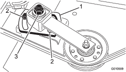
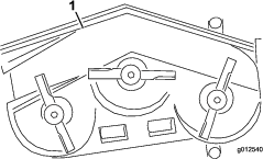
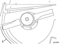
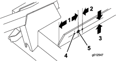
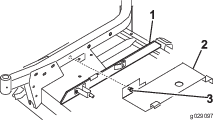
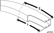
Lower the cutting unit and remove the 4 bolts and
nuts securing lift arm brackets to castor arms (Figure 2).
-
Start the engine and raise the traction unit lift
arms.
-
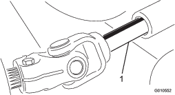
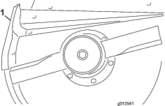
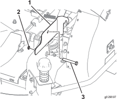
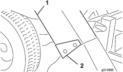
Shut off the engine and slide the cutting unit away
from the traction unit, separating the male and female sections of
PTO shaft (Figure 3).
Caution
If the engine is started and the PTO shaft is allowed to rotate,
serious injury could result.
Do not start the engine and engage the PTO lever when the PTO
shaft is not connected to the gear box on the cutting unit.
Installing the New Spindle Pulley
Parts needed for this procedure:
| Double pulley | 1 |
| Pulley nut | 1 |
| Nut cover | 1 |
-
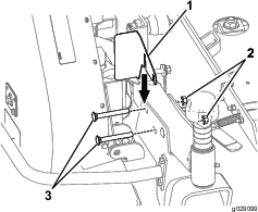
Unhook the latches securing the right cover to the
top of the cutting unit. Remove the cover from the cutting unit.
-
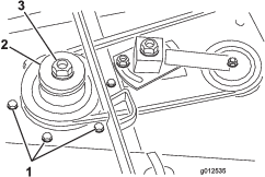
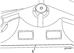
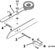
Loosen the 2 nuts securing the idler plate so the
tension of the idler pulley against the belt is released (Figure 4).
-
Remove the belt from the right spindle pulley (Figure 4).
-
Remove the six carriage bolts and flange nuts securing
the spindle housing assembly to the cutting unit (Figure 5). Slide
the spindle housing assembly out of the bottom of the cutting unit.
-
Remove the nut and washer retaining the pulley on
the spindle shaft. Remove the pulley from the shaft.
-
Slide the new double spindle pulley onto the spindle
shaft. Do not install the pulley nut at this time.
-
Slide the pulley end of spindle housing assembly through
the hole in the cutting unit, and loop the belt around the pulley
and idler. Mount the spindle assembly in place with 6 carriage bolts
and flange nuts.
-
Install the original washer and new pulley nut onto
the spindle shaft and tighten it to 100 ft-lb (135.5 N⋅m). Install
the nut cover.
-
Adjust (tighten) the idler adjusting nut to 35 to
40 ft-lb (48 to 54 N⋅m) to achieve the proper belt tension. Tighten
the idler plate nuts.
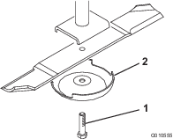
Installing the New Blades
Parts needed for this procedure:
-
Grasp the end of blade using a thickly padded glove.
Remove the blade bolt, anti-scalp cup, and blade from the spindle
shaft (Figure 6).
-
In sequence, install a new blade (sail facing toward
the cutting unit) and anti-scalp cup. Secure the parts in place with
the blade bolt. Tighten the blade bolt to 85 to 110 ft-lb (115 to
149 N⋅m).
-
Repeat this procedure on all blades.
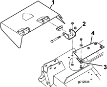
Removing and Modifying the Grass Deflector
Parts needed for this procedure:
-
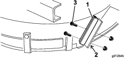
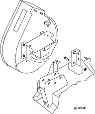
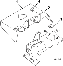
Remove the bolts, locknuts, and springs securing the
deflector mounts to the pivot brackets (Figure 7). Remove the deflector.
-
Remove the carriage bolts and flange nuts securing
the pivot brackets to the housing (Figure 7). Remove the pivot brackets.
Retain the fasteners for future use.
-
Remove the 2 carriage bolts, flat washers, and locknuts
securing the reinforcement plate to the under side of the housing
and the stiffener plate to the top of the housing (Figure 7).
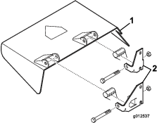
-
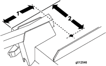
Using the bolts, locknuts, and springs previously
removed, install the new pivot brackets to the deflector mounts (Figure 8). Do not
over tighten the nuts because the brackets must be allowed to pivot.
Save this assembly for side discharge operation.
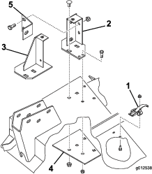
Installing the Blower Mounting Brackets
Parts needed for this procedure:
| Blower assembly with mounting brackets | 1 |
| Capscrew, 5/16 x 1 inch | 3 |
| Locknut, 5/16 | 4 |
| Carriage bolt, 3/8 inch x 3/4 inch | 4 |
| Flange nut, 3/8 inch | 3 |
-
Remove the fasteners securing the right hand deck
cover spring latch to the right side of the cutting deck (Figure 9). Remove
and retain the latch for future use with the right hand cover.
-
Position the blower and mounting brackets on the deck,
aligning the mounting holes with the holes previously used for mounting
the grass deflector. Figure 9 is shown with the blower removed from the brackets.
Make sure there is no gap between the blower and cutting deck.
-
Position the new reinforcement plate under the deck
aligning the mounting holes with the holes previously used for mounting
the grass deflector (Figure 9).
-
Mount the front and rear brackets and reinforcement
plate to the deck with 2 previously removed carriage bolts (3/8 -16
x 7/8 inch) and flange nuts each (Figure 9). The bolt heads must be on
top of the deck.
-
Remove the 2 knobs securing the blower to the mounting
brackets. Remove the blower.
-
Using each bracket as a template, mark the location
and drill 2 additional 11/32 inch diameter holes. (2 holes for the
rear bracket and 1 for the front bracket. Use the reinforcement plate
for a template to drill one of the 11/32 inch diameter holes for the
rear bracket.
Note: Use caution when drilling the holes so that the castor arm is
not damaged.
-
Secure the brackets and reinforcement plate to the
deck with bolts (5/16-18 x 3/4 inch) and locknuts (Figure 9). The bolt
heads must be on top of the deck.
-
Mount the blower brace to the rear mounting bracket
with 2 bolts (3/8-16 x 1 inch) and locknuts (Figure 9) and to the castor arm with
a bolt (3/8-16 x 1 inch).
-
When mounting the lift arm brackets to the castor
arms, mount other side of the blower brace to the lift arm bracket
and the right castor arm with the bolt and nut previously removed.
Installing the Deck Deflectors
Parts needed for this procedure:
| Front deflector | 1 |
| Rear deflector | 1 |
| Rear shelf | 1 |
| Left shelf | 1 |
| Right shelf | 1 |
| Capscrew, 5/16 x 5/8 inch | 6 |
| Locknut, 5/16 inch | 6 |
| Capscrew, 3/8 x 1 inch | 4 |
| Lockwasher, 3/8 inch | 4 |
| Capscrew, 1/4 x 1 inch | 3 |
| Capscrew, 1/4 x 3/4 inch | 3 |
| Locknut, 1/4 inch | 6 |
-
Insert the front deflector into the deck, aligning
the end of the deflector with the edge of the discharge opening (Figure 11 and Figure 12).
-
Using the deflector as a template, mark and drill
three 11/32 inch diameter holes through front and top of deck.
-
Secure the 2 front mounting tabs of deflector to the
deck with bolts (5/16-18 x 5/8 inch) and locknuts (5/16-18 inch).
-
Secure the front right corner of the front mounting
bracket and the top tab of the deflector to the deck with a bolt (5/16-18
x 1 inch) and locknut.
-
Using the deflector as a template, mark and drill
three 11/32 inch diameter holes through the deck.
-
Secure the deflector to the deck with 3 bolts (5/16-18
x 5/8 inch) and locknuts (5/16-18 inch).
-
Before mounting the left and right shelves to the
deck, you must grind the welds off of the bottom edge of the deck.
Paint the deck after grinding.
-
Using the existing holes, mount the rear shelf to
the deck with 4 bolts (3/8-16 x 1 inch) and lock washers (3/8 inch)
(Figure 14).
-
Align the left shelf with the left end of the rear
shelf and the edge of the deck (Figure 12 and Figure 14).
-
Secure the left shelf to the deck with 2 bolts (1/4-20
x 1 inch), 1 bolt (1/4-20 x 3/4 inch), and 3 locknuts (Figure 15). Position
the bolt heads to the inside of the deck.
-
Align the right shelf with the right end of the rear
shelf and the edge of the deck (Figure 12 and Figure 16). Using the left shelf as
a template, locate, mark, and drill three 9/32 inch diameter holes
in the deck.
-
Secure the right shelf to the deck with 1 bolt (1/4-20
x 1 inch), 2 bolts (1/4-20 x 3/4 inch), and 3 locknuts. Position the
bolt heads to the inside of the deck.
Mounting the New Deflector Stop
Parts needed for this procedure:
| Deflector stop | 1 |
| Capscrew, 1/4 x 3/4 inch | 2 |
| Locknut, 1/4 inch | 2 |
-
Using the new deflector stop as a template, set it
on the original flat deflector stop (Figure 17). Ensure that the new deflector
stop is flush at the bottom, contacting the side of the deck, and
parallel with the outside edge of the deflector support.
-
Locate, mark and drill two 9/32 inch diameter holes
through the old deflector support.
-
Mount the new deflector support to the old deflector
stop with 2 bolts (1/4-20 x 3/4 inch) and locknuts (1/4-20 inch),
as shown in Figure 17.
Mounting the Idler Assembly
Parts needed for this procedure:
| Idler arm assembly | 1 |
| Pivot screw | 1 |
| Bushing | 1 |
| Washer | 2 |
| Locknut, 3/8 inch | 1 |
| Spring | 1 |
| Threaded rod | 1 |
| Flange nut, 5/16 inch | 2 |
| Spring bracket | 1 |
| Capscrew, 1/4 x 1 inch | 2 |
| Locknut, 1/4 inch | 2 |
-
Using the dimensions shown in Figure 18, locate, mark, and drill a
13/32 inch diameter hole in the deck. The dimensions shown are from
the right front corner of the deck and from the edge of the discharge
opening. The blower brackets are removed for clarity.
-
Using the dimensions shown in Figure 19, locate, mark, and drill a
13/16 inch diameter hole and two 13/32 inch diameter holes in the
right bridge bar.
-
Thread a flange nut (5/16-18 inch) approximately
2 inches (5 cm) onto the threaded rod (Figure 20).
-
Insert the end of the threaded rod through the large
hole in the spring bracket and loosely secure it with another flange
nut (5/16-18 inch) (Figure 20). Do not tighten the flange nuts.
-
Insert the other end of the threaded rod through the
hole in the bridge bar and secure the spring bracket to the bridge
with 2 bolts and locknuts (Figure 20).
-
Hook the short loop of the spring into the hole in
the threaded rod and the long loop in the hole in the idler arm (Figure 20).
-
Mount the idler pulley arm to the deck with a pivot
screw (3/8-16 inch), a thrust washer (1/2 inch), the idler arm, a
thrust washer (3/8 inch), and a locknut (3/8-16 inch) beneath the
deck (Figure 20).
Important: Do not tighten the flange nuts on the threaded rod at this time.
Adjust the spring tension after the blower assembly and belt have
been installed.
Mounting the Blower
Parts needed for this procedure:
-
Route the belt around the small deck spindle pulley.
-
Slide the blower onto the mounting bracket alignment
studs (Figure 21) while routing the belt around the blower pulley.
Note: If the blower does not easily slide onto the mounting brackets,
loosen the alignment bolts slightly.
-
Secure the blower to the brackets with 2 knobs.
-
Adjust the spring length to 4-7/8 inches (12.4 cm)
for proper belt tension by adjusting the flange nuts on the threaded
rod.
Install the Bumper
Parts needed for this procedure:
| Bumper | 1 |
| Capscrew, 5/16 x 3 inch | 4 |
| Locknut, 5/16 inch | 4 |
-
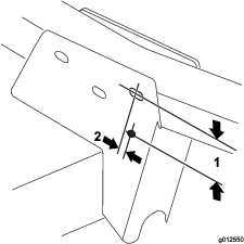
Using dimensions shown in Figure 22, locate, mark and drill a
11/32 inch diameter hole through both walls of the right front castor
arm bracket.
-
Secure the top mounting hole of the front mounting
plate of the bumper to the castor arm bracket with a bolt (5/16 -18
x 3 inch) and locknut (Figure 23).
-
Using both mounting plates of the bumper as templates,
locate, mark, and drill 3 additional 11/32 inch diameter holes through
both walls of the front and rear castor arm brackets.
Installing the New Deck Cover
Parts needed for this procedure:
| Trim molding | 1 |
| Deck cover | 1 |
-
Insert a trim molding onto the right bridge bar, so
the side of the spring bracket is 10 cm (4 inches) to the far edge
of the trim molding (Figure 24).
-
Hook the rear of the deck cover (Figure 24) onto the
rear channel pin while aligning the cover mounting bolt with the hole
in the right castor arm. The cover is to rest on the trim molding.
Adjust the molding as required.
-
Secure the cover to the right castor arm with the
bolt.
Installing the New Safety Guards
Parts needed for this procedure:
| Belt guard | 1 |
| Pulley guard | 1 |
-
Install the belt guard onto the machine (Figure 25).
Note: Use existing hardware on the machine by removing it and using
it to install the guard.
-
Install the pulley guard onto the machine (Figure 26).
Note: Use existing hardware on the machine by removing it and using
it to install the guard.
Installing the New Counterbalance Spring
Parts needed for this procedure:
To compensate for the additional weight of the blower assembly,
the original light counterbalance spring at the right side of the
machine, must be replaced with the heavier spring included (Figure 27).
-
Remove the hair pin cotter and clevis pin and slide
the spring assembly out of the retaining bracket.
-
Screw the spring off of the top and bottom mounting
brackets.
-
Screw the new heavy spring onto both mounting brackets.
Ensure that the spring is completely threaded through all holes and
it contacts the flat side of the bracket.
-
Install the spring assembly into the retaining bracket
with a clevis pin and hairpin cotter.
Installing the Cutting Unit to the Traction Unit
-
Engage the parking brake, ensure that the traction
pedal is in neutral and the PTO lever is in the Off position. Start
the engine and raise the lift arms. Shut off the engine.
-
Position the cutting unit in front of the traction
unit and align the gear case input shaft with the PTO shaft; install
the shaft.
-
Carefully lower the lift arms while aligning the lift
arm brackets with the castor arms. Align the PTO shaft hole with the
gear case input shaft hole and install the roll pin.
-
Secure the lift arm brackets and the side of the blower
brace to the castor arms with 4 bolts and nuts.
-
Start the engine and raise the cutting unit. Secure
the counterbalance springs to the cutting unit with shoulder bolts
and locknuts.
Installing the New Decal
Parts needed for this procedure:
Install the Danger Decal (Part Number 66-1340 or 93-7824 for
CE) on the front edge of the deck, inside the right castor arm.
Mounting the Blower Housing Chute
Parts needed for this procedure:
Important: When the chute in the Blower Kit is used with a 15 cubic foot
Hopper Kit, you must cut off a section of the chute to ensure proper
fit between the blower and the hopper. If used with another kit, proceed
to step 3.
-
Using the dimensions shown in Figure 28, use a tape measure and mark
the chute.
Note: For convenience, some chutes may have a light scribe mark where
the chute must be cut off.
-
Draw lines around all sides of the chute and cut off
with a saw.
-
Set the deck to the desired height-of-cut setting.
-
Slide the chute over the blower opening and onto the
mounting studs (Figure 29).
-
Lower the hopper hood and align the chute with the
hood snout. Secure the chute in position with 4 locknuts (5/16 inch)
and chute brackets. Position the wide end of brackets to the rear.