
 , which means
Caution, Warning, or Danger—personal safety instruction. Failure
to comply with these instructions may result in personal injury or
death.
, which means
Caution, Warning, or Danger—personal safety instruction. Failure
to comply with these instructions may result in personal injury or
death.


Maintenance
Note: Determine the left and right sides of the machine from the normal operating position.
Supporting the Cutting Unit
Whenever you need to tip the cutting unit to expose the bedknife/reel, prop up the rear of the cutting unit to ensure that the nuts on the back end of the bedbar adjusting screws are not resting on the work surface (Figure 8).
Adjusting the Bedknife to Reel Contact
Adjusting the Bedknife Daily
Prior to mowing each day, or as required, check each cutting unit to verify proper bedknife-to-reel contact. Perform this check even though quality of cut is acceptable.
-
Lower the cutting units onto a hard surface.
-
Shut off the machine as follows:
-
Gas units: Shut off the engine and disconnect the spark-plug wire.
-
Electric units: Turn off the machine and disconnect the battery connector (T-handle).
-
-
Slowly rotate the reel in a reverse direction, listening for reel-to-bedknife contact.
-
If no contact is evident, turn the bedbar adjusting screws clockwise (Figure 9), 1 click at a time, until you feel and hear light contact.
Note: The reel must cut one sheet of paper, when inserted at a right angle to the bedknife, at both ends and the center of the reel.
Note: The bedbar adjusting screws have detents corresponding to 0.018 mm (0.0007 inch) bedknife movement for each indexed position.
-
If excessive contact/reel drag is evident, you need to backlap, reface the front of the bedknife, or regrind the cutting unit to achieve the sharp edges needed for precision cutting (Refer to the Toro Manual for Sharpening Reel and Rotary Mowers, Form No. 09168SL).
Important: Light contact is preferred at all times. If you do not maintain light contact, the bedknife/reel edges will not sufficiently self-sharpen, and dull cutting edges will result after a period of operation. If you maintain excessive contact, bedknife/reel wear will be accelerated, uneven wear can result, and the quality of cut may decline.
Note: For eFlex cutting units, the reel-to-bedknife contact has a significant impact on energy consumption. Very light contact is best for cutting performance and battery consumption.
Note: As the reel blades continue to run against the bedknife, a slight burr will appear on the front cutting edge surface along the full length of the bedknife. Occasionally run a file across the front edge to remove this burr to improve cutting.After extended running, a ridge eventually develops at both ends of the bedknife. Round off these notches or file them flush with the cutting edge of the bedknife to ensure smooth operation.
-
Adjusting the Bedknife after Grinding, Backlapping, or Disassembly
Use this procedure after grinding, backlapping, or disassembling the reel. This is not a daily adjustment.
Note: For eFlex cutting units, the reel-to-bedknife contact has a significant impact on energy consumption. Very light contact is best for cutting performance and battery consumption.
-
Position the cutting unit on a flat, level work surface.
-
Tip the cutting unit to expose the bedknife and reel.
Note: Ensure that the nuts on the back of the bedbar adjusting screws are not resting on the work surface (Figure 8).
-
Rotate the reel so that 1 of the blades crosses the bedknife edge between the first and second bedknife screw heads located on the right side of the cutting unit.
-
Make and identifying mark on the blade where it crosses the bedknife edge.
Note: Doing this will make later adjustments easier.
-
Insert a 0.05 mm (0.002 inch) shim between the blade and the bedknife edge at the point marked in step 4.
-
Turn the right bedbar adjusting screw (Figure 9) until you feel light pressure on the shim when sliding it side-to-side. Remove the shim.
-
For the left side of the cutting unit, slowly rotate the reel so that the closest blade crosses the bedknife edge between the first and second screw heads.
-
Repeat steps 4 through 6 for the left side of the cutting unit and left bedbar adjusting screw.
-
Repeat steps 5 and 6 until there is light pressure at the contact points on both the left and right sides of the cutting unit.
-
To obtain light contact between the reel and bedknife, turn each bedbar adjusting screw clockwise 3 click.
Note: Each click on the bedbar adjusting screw moves the bedknife 0.018 mm (0.0007 inches). Do not overtighten the adjusting screws.Turning the adjusting screw clockwise moves the bedknife edge closer to the reel. Turning the adjusting screw counterclockwise moves the bedknife edge away from the reel.
-
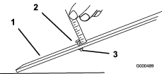
Test the cutting performance by inserting a long strip of cutting performance paper between the reel and bedknife, perpendicular to the reel and bedknife (Figure 10). Slowly rotate the reel forward to cut the paper.
Note: If excessive contact/reel drag is evident, you may need to backlap or grind the reel and bedknife to achieve the sharp edges needed for precision cutting.
Grinding the Bedknife
Relief-Grinding the Reel
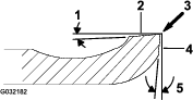
The new reel has a land width of 0.76 to 1.27 mm (0.030 to 0.050 inch) and a 30 degree relief grind.
When the land width gets larger than 3 mm (0.120 inch) wide, do the following:
-
Apply a 30 degree relief grind on all reel blades until the land width is 0.76 to 1.27 mm (0.030 to 0.050 inch) wide (Figure 11.
-
Spin grind the reel to achieve <0.025 mm (0.001 inch) reel run-out.
Note: This causes the land width to grow slightly.
Note: To extend the longevity of the sharpness of the edge of the reel and the bedknife—after grinding the reel and/or the bedknife—check the reel to bedknife contact again after cutting 6 greens, as any burrs will be removed, which may create improper reel to bedknife clearance and thus accelerate wear.
Checking the Top Grind Angle
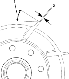
The angle that you use to grind your bedknives is very important.
Use the angle indicator and the angle-indicator mount to check the angle that your grinder produces and then correct for any grinder inaccuracy.
-
Place the angle indicator on the bottom side of the bedknife as shown in Figure 12.
-
Press the Alt Zero button on the angle indicator.
-
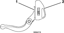
Place the angle-indicator mount on the edge of the bedknife so that the edge of the magnet mates with the edge of the bedknife (Figure 13).
Note: The digital display should be visible from the same side during this step as it was in step 1.
-
Place the angle indicator on the mount as shown in Figure 13.
Note: This is the angle that your grinder produces, and should be within 2 degrees of the recommended top grind angle.
Reel Grinding Specifications
| Reel Diameter (New) | 128.5 mm (5.06 inches) |
| Service Limit–Reel Diameter | 114.3 mm (4.50 inches) |
| Reel Shaft Diameter (OD) | 34.9 mm (1.375 inches) |
| Blade Relief Angle | 25 to 35° |
| Blade Land Width | 0.76 to 1.27 mm (0.030 to 0.50 inch) |
| Blade Land Width Range | 0.8 to 1.2 mm (0.030 to 0.050 inch) |
| Service Limit–Reel Diameter Taper | 0.25 mm (0.010 inch) |
Adjusting the Rear Roller Height
Depending on your desired height-of-cut range, adjust the rear roller brackets (Figure 14 or Figure 15) to the low or high position:
-
Position the spacer above the sideplate-mounting flange (factory setting) when the height-of-cut settings range from 1.5 mm to 6 mm (1/16 inch to 1/4 inch) as shown in Figure 14.
-
Position the spacer below the sideplate-mounting flange when the height-of-cut settings range from 3 mm to 25 mm (1/8 inch to 1 inch) as shown inFigure 15.
-
Raise the rear of the cutting unit and place a block under the bedknife.
-
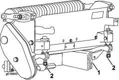
Remove the 2 nuts securing each roller bracket and spacer to each sideplate mounting flange.
-
Lower the roller and screws from the sideplate mounting flanges and spacers.
-
Place the spacers onto the screws above of below the roller brackets, as required (Figure 14 or Figure 15).
-
Secure the roller bracket and spacers to the underside of the mounting flanges with the nuts previously removed.
-
Verify that the bedknife-to-reel contact is correct. Tip the mower to expose the front and rear rollers and the bedknife.
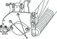
Note: The position of the rear roller to the reel is controlled by the machining tolerances of the assembled components and paralleling is not required. A limited amount of adjustment is possible by setting the cutting unit on a surface plate and loosening the sideplate mounting bolts (Figure 16). Adjust and tighten the bolts when finished.
Important: Whenever you must tip the cutting unit to expose the bedknife/reel, prop up the rear of the cutting unit to ensure that the nuts on the back end of the bedbar adjusting screws are not resting on the work surface (Figure 8).
Adjusting the Height of Cut
This cutting unit comes standard with the Edgemax Micro-cut bedknife and standard bedbar. The effective height of cut depends on previous mower configurations and turf conditions (i.e., roller type, bedknife behind center distance, soft or firm greens, season conditions). Set the initial height of cut 0.25 mm to 0.38 mm (0.010 to 0.015 inch) higher than the previous greensmower setup and adjust it to match conditions.
Note: For heights of cut greater than 13 mm (0.500 inch), install the high-height-of-cut kit.
Use the following chart to determine which bedknife is best suited for the desired height of cut.
| Recommended Bedknife/Height of Cut Chart | ||
| Bedknife | Part Number | Height of Cut |
| Edgemax Micro-cut (Standard) | 115-1880 (2100)117-1530 (1800) | 1.5 to 4.7 mm (0.062–0.188 inch) |
| Edgemax Tournament (Optional) | 115-1881 (2100)117-1532 (1800) | 3.1 to 12.7 mm (0.125–0.500 inch) |
| Micro-cut (Optional) | 93-4262 (2100)98-7261 (1800) | 1.5 to 4.7 mm (0.062–0.188 inch) |
| Tournament (Optional) | 93-4263 (2100)98-7260 (1800) | 3.1 to 12.7 mm (0.125–0.500 inch) |
| Extended Micro-cut (Optional) | 108-4303 (2100)110-2300 (1800) | 1.5 to 4.7 mm (0.062–0.188 inch) |
| Extended Tournament (Optional) | 108-4302 (2100) | 3.1 to 12.7 mm (0.125–0.500 inch) |
| Low-cut (Optional) | 93-4264 (2100)110-2301 (1800) | 4.7 to 25.4 mm (0.188–1.00 inch) |
-
Loosen the locknuts securing the height-of-cut arms to the cutting-unit side plates (Figure 17).
-
Loosen the nut on the gauge bar and set the adjusting screw to the desired height of cut (Figure 18).
Note: The distance between the bottom of the screw head and the face of bar is the height of cut.
-
Hook the screw head onto the cutting edge of the bedknife and rest the rear end of the bar onto the rear of the roller (Figure 19).
-
Rotate the adjusting screw until the roller contacts the front of the gauge bar.
-
Adjust both ends of the roller until the entire roller is parallel to the bedknife.
Important: When set properly, the rear and front rollers contact the gauge bar and the screw is snug against the bedknife. This ensures that the height of cut is identical at both ends of the bedknife.
-
Tighten the nuts to secure the adjustment enough to remove play from the washer.
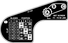
Adjusting the Clip Setting
There are 6 clip settings on the cutting unit that you can set to match your turf conditions. Start out setting the clip to match the height of cut, but then test the cutting unit and adjust the clip to obtain the quality of cut that you desire.
-
Shut off the machine as follows:
-
Gas units: Shut off the engine and disconnect the spark-plug wire.
-
Electric units: Turn off the machine and disconnect the battery connector (T-handle).
-
-
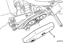
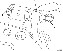
Loosen the flange bolt securing the belt cover and remove the belt cover to expose the belt (Figure 20).
-
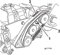
Loosen the bearing-housing nut (Figure 21).
-
Using a 16 mm (5/8 inch) wrench, rotate the bearing housing to make sure it operates freely.
-
Remove the belt (Figure 21).
-
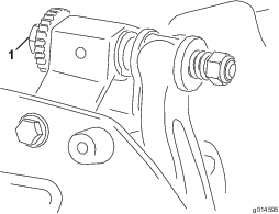
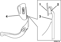
Using the chart shown on the decal in Figure 22, determine the clip setting you want and which pulleys you will need to move.
Note: Each pulley is numbered (22, 24, and 25). Move the pulleys to the positions indicated in the chart for your clip setting.
-
Loosen the 2 set screws on each pulley you need to move using a hex wrench.
-
Remove each pulley.
-
Install each pulley in the new configuration as indicated on the decal (Figure 22).
Note: Ensure that the setscrews on each pulley are positioned to align with the key and flat area on the shaft.
-
Torque the setscrews to 8.3 to 8.9 N·m (74 to 79 in-lb).
-
Install the belt.
-
Ensure that the compression spring is applying tension to the belt (Figure 21).
-
Tighten the bearing-housing nut.
-
Install the belt cover.
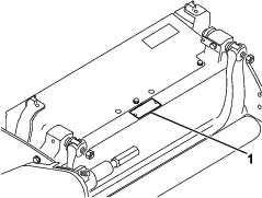
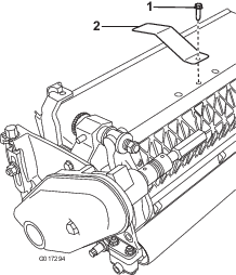
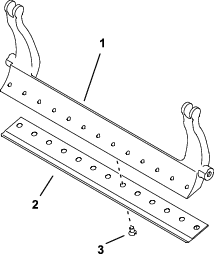
Adjusting the Cut-Off Bar
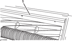
Adjust the cut-off bar to ensure that the clippings are cleanly discharged from the reel area, as follows:
Note: The bar is adjustable to compensate for changes in turf conditions. Adjust the bar closer to the reel when the turf is extremely dry. By contrast, adjust the bar further away from the reel when the turf conditions are wet. The bar should be parallel to the reel to ensure optimum performance. Adjust it after sharpening the reel on a reel grinder.
-
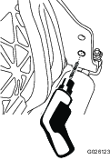
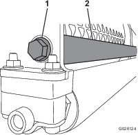
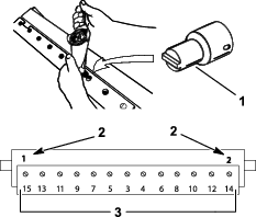
Loosen the screws securing the top bar (Figure 23) to the cutting unit.
-
Insert a 1.5 mm (0.060 inch) feeler gauge between the top of the reel and the bar and tighten the screws.
Important: Ensure that the bar and reel are equal distance apart across the complete reel.
Servicing the Bedbar/Bedknife
Only a properly trained mechanic should service the bedbar and bedknife to prevent damage to the reel, bedbar, or bedknife. Take the cutting unit to your authorized Toro distributor for service. Refer to the Service Manual for your traction unit for complete instructions, special tools, and diagrams for servicing the bedknife. Should you need to remove or assemble the bedbar yourself, the instructions and specifications for servicing the bedknife are provided below.
Important: Always follow the bedknife procedures detailed in your Service Manual when servicing the bedknife. Failure to install and grind the bed knife correctly can damage to the reel, bedbar, or bedknife.
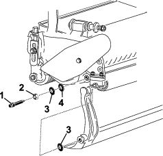
Removing the Bedbar
-
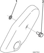
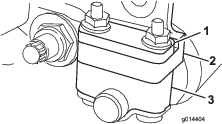
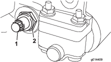
Turn the bedbar adjusting screw counterclockwise to back the bedknife away from the reel (Figure 24).
-
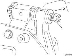
Back out the spring-tension nut until the washer is no longer tensioned against the bedbar (Figure 24).
-
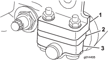
On each side of the machine, loosen the locknut securing the bedbar bolt (Figure 25).
-
Remove each bedbar bolt, allowing you to pull down the bedbar, and remove it from the machine bolt (Figure 25).
Account for the 2 nylon and 2 stamped steel washers on each end of the bedbar (Figure 26).
Assembling the Bedbar
-
Install the bedbar, positioning the mounting ears between the washer and bedbar adjuster.
-
Secure the bedbar to each side plate with the bedbar bolts (nuts on bolts) and 4 washers (8 total).
-
Position a nylon washer on each side of the side-plate boss. Place a steel washer outside each of the nylon washers (Figure 26).
-
Torque the bedbar bolts to 27 to 36 N∙m (240 to 320 inch-lb). Tighten the locknuts by hand until the outside steel washer stops rotating and there is no end play. The washers on the inside may have a gap.
Important: Do not overtighten the locknuts or they will deflect the side plates.
-
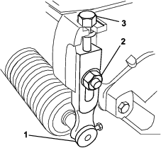
Tighten the spring tension nut until the spring collapses, then back it off 1/2 turn (Figure 27).
Installing the Bedknife
-
Remove the rust, scale, and corrosion from the bedbar surface and apply a thin layer of oil to the bedbar surface.
-
Clean the screw threads.
-
Apply never-seize compound to the screws and install the bedknife to the bedbar.
-
Torque the 2 outer screws to 1 N∙m (10 in-lb).
-
Working form the center of the bedknife, torque the screws to 23 to 28 N∙m (200 to 250 in-lb).
-
Grind the bedknife.
Bedknife Specifications
Bedknife Grinding Specifications
| Standard bedknife relief angle | 3° Minimum |
| Extended bedknife relief angle | 7° Minimum |
| Front angle range | 13° to 17° |
Backlapping the Reel
Danger
Contact with the reel or other moving parts can result in personal injury.
Keep your fingers, hands, and clothing away from the reels or other moving parts.
-
Stay away from the reel while backlapping.
-
Never use a short-handled paint brush for backlapping. For handle assembly parts, contact your authorized Toro distributor.
You can backlap the reels either by leaving the cutting unit on the traction unit or removing the cutting unit completely from the traction unit. If you leave the cutting unit on the traction unit, move the hex coupler between the main drive and cutting unit drive to the decoupled position to prevent excessive wear to the reel brake.
-
Position the machine on a clean, level surface.
-
Shut off the machine as follows:
-
Gasoline units: Shut off the engine and disconnect the spark-plug wire.
-
Electric units: Turn off the machine and disconnect the battery connector (T-handle).
-
-
Engage the parking brake.
-
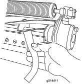
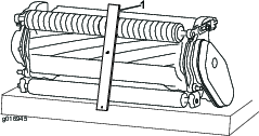
Connect the backlapping machine to the cutting unit by connecting a 1/2-inch hex socket to the reel pulley output shaft on the left side of the cutting unit.
Note: Additional instructions and procedures on backlapping are available in the Toro Sharpening Reel and Rotary Mowers Manual (Form No. 80-300PT).
Note: For a better cutting edge, run a file across the front face of the bedknife when you complete the lapping operation. This removes any burrs or rough edges that may have built up on the cutting edge. A very light file touch may be necessary on the top edge to break the burr off completely from the cutting edge.
Note: If you leave the cutting unit attached to the machine during backlapping, couple the hex shaft of the machine back to the cutting unit.