Warning
CALIFORNIA
Proposition 65 Warning
Use of this product may cause exposure to chemicals known to the State of California to cause cancer, birth defects, or other reproductive harm.
Safety
Safety and Instructional Decals
 |
Safety decals and instructions are easily visible to the operator and are located near any area of potential danger. Replace any decal that is damaged or missing. |

Installation
Preparing the Machine
-
Connect the machine to the tow vehicle; refer to the Operator's Manual for the machine.
-
Lower the mower decks; refer to the Operator’s Manual for your machine.
-
Engage the parking brake for the tow vehicle, shut off the engine, remove the key, and wait for all moving parts to stop before leaving the operator’s seat.
-
Chock the tires of the machine.
-
Lower the jack and support the machine; refer to the Operator's Manual for the machine.
Important: You must fully support the weight of the machine with the jack.
-
Disconnect the machine from the tow vehicle.
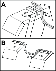
Assembling the Fenders
Parts needed for this procedure:
| Fender | 2 |
| Support tube | 2 |
| Flange-head capscrew (5/16 x 1-3/4 inches) | 4 |
| Flange locknut (5/16 inch) | 4 |
-
Assemble the support tube to the bracket of the fender with 2 flange-head capscrews (5/16 x 1-3/4 inches) and 2 flange locknuts (5/16 inch) as shown in Figure 1.
-
Assemble the other support tube to the other fender bracket with 2 flange-head capscrews (5/16 x 1-3/4 inches) and 2 flange locknuts (5/16 inch).
-
Torque the nuts and bolts to 1978 to 2542 N∙m (175 to 225 in-lb).
Drilling the Axle Frame Tube
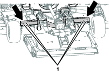
If your machine does not have holes in the axle frame tube (Figure 2) for the fender kit, perform the following steps:
-
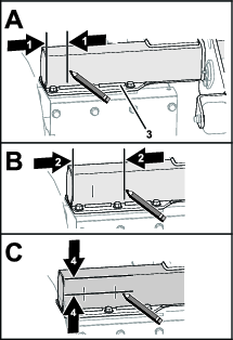
Measure 51 mm (2 inches) from the end of the axle frame tube, and mark the tube as shown in Figure 3A.
-
Measure 127 mm (5 inches) from the end of the axle frame tube, and mark the tube as shown in Figure 3B.
-
Measure 44.5 mmm (1-3/4 inches) from the top of the axle frame tube, and mark the tube as shown in Figure 3C.
-
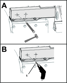
Centerpunch the marks where they intersect (Figure 4).
-
Drill the centerpunch marks with a 11 mm (7/16 inch) drill bit (Figure 4) through both walls of the tube.
-
Repeat steps 1 through 5 at the other end of the axle frame tube
Installing the Fenders onto the Machine
Parts needed for this procedure:
| Capscrew (5/16 x 4 inches) | 4 |
| Washer (5/16 inch) | 4 |
| Flange locknut (5/16 inch) | 4 |
-
Align the holes in the support tube for the left fender to the holes in the axle frame tube as shown in Figure 5.
Note: Ensure that the decal is aligned rearward of the fender-support tube.
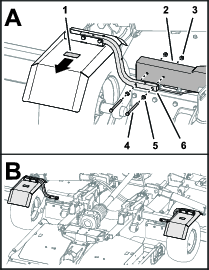
-
Assemble the fender-support tube to the axle frame tube (Figure 5) with 2 capscrews (5/16 x 4 inches). 2 washers (5/16 inch), and 2 flange locknuts (5/16 inch).
-
Torque the nuts and bolts to 1978 to 2542 N∙m (175 to 225 in-lb).
-
Repeat steps 1 through 3 for the fender at the other side of the machine.