| Maintenance Service Interval | Maintenance Procedure |
|---|---|
| Before each use or daily |
|
| After each use |
|
Introduction
This machine is designed to mix mortar, plaster, fireproofing material, grout, and other small-grained cement products. A vehicle equipped with an appropriate pintle hitch or ball hitch can tow the machine..
Read this information carefully to learn how to operate and maintain your product properly and to avoid injury and product damage. You are responsible for operating the product properly and safely.
You may contact Toro directly at www.Toro.com for product safety and operation training materials, accessory information, help finding a dealer, or to register your product.
Whenever you need service, genuine Toro parts, or additional information, contact an Authorized Service Dealer or Toro Customer Service and have the model and serial numbers of your product ready. Write the numbers in the space provided.
This manual identifies potential hazards and has safety messages identified by the safety alert symbol (Figure 2), which signals a hazard that may cause serious injury or death if you do not follow the recommended precautions.

This manual uses 2 words to highlight information. Important calls attention to special mechanical information and Note emphasizes general information worthy of special attention.
The DOT tire information is located on the side of each tire. This information gives load and speed ratings. Replacement tires should have the same or better ratings.
Note: The various machines in this manual have different weights; refer to Specifications to ensure that the tires on your machine meet or exceed the weight requirements of your machine.
Warning
CALIFORNIA
Proposition 65 Warning
The power cord on this product contains lead, a chemical known to the State of California to cause birth defects or other reproductive harm. Wash hands after handling.
Use of this product may cause exposure to chemicals known to the State of California to cause cancer, birth defects, or other reproductive harm.
Safety
Improperly using or maintaining the machine can result
in injury. To reduce the potential for injury, comply with these safety
instructions and always pay attention to the safety alert symbol  , which means: Caution, Warning, or Danger—personal safety instruction. Failure to comply with the instruction
may result in personal injury or death.
, which means: Caution, Warning, or Danger—personal safety instruction. Failure to comply with the instruction
may result in personal injury or death.
Safe Operating Practices
This product is capable of amputating hands. Always follow all safety instructions to avoid serious injury or death.
Warning
Machining or handling stone, masonry, concrete, metal, and other materials can generate dust, mists, and fumes containing chemicals, such as silica, known to cause serious or fatal injury or illness, such as respiratory disease, silicosis, cancer, birth defects, or other reproductive harm.
-
Control dust, mist, and fumes at the source where possible. Water should be used for dust suppression when feasible.
-
Use good work practices and follow the recommendations of the manufacturer or suppliers, OSHA, and other occupational and trade associations.
-
Always follow respiratory precautions.
-
When the hazards from inhalation cannot be eliminated, the operator and any bystanders should wear a respirator approved by OSHA for the material being handled.
Training
-
Read the Operator's Manual and other training material. If the operator(s) or mechanic(s) cannot read or understand the information, it is the owner's responsibility to explain this material to them.
-
Become familiar with the safe operation of the equipment, operator controls, and safety signs.
-
All operators and mechanics should be trained. The owner is responsible for training the users.
-
Never let children or untrained people operate or service the equipment. Local regulations may restrict the age of the operator.
-
The owner/user can prevent and is responsible for accidents or injuries to people or damage to property.
Towing
Check with your local county or state towing safety regulations before towing the machine.
-
In order to reduce the possibility of an accident while transporting the machine on public roads, make sure the towing vehicle is mechanically sound and in good operating condition.
-
Turn off the motor before transporting the machine.
-
When towing with a ball hitch, ensure that the ball hitch you are using is the proper size for the hitch coupler on the machine.
-
When towing with a pintle hitch, ensure that the eye of the tow pole is the correct dimension for the pintle hook.
-
Inspect the hitch and coupling for wear. Never tow the machine with damaged or defective hitches, couplings, chains, or other components.
-
Check the tire air pressure on the towing vehicle and the machine.
-
Check the tire tread and sidewall for damage and wear.
-
Properly attach the safety chains to the towing vehicle.
-
Ensure that the directional and brake lights are working properly (if the machine is equipped with the light kit).
-
Ensure that the directional, backup, and brake lights of the tow vehicle are working properly.
-
Before towing, check to make certain your machine is correctly and securely attached to the towing vehicle.
-
Ensure that the safety chains are properly secured to the vehicle, and leave enough slack for turning.
-
Do not carry any material in the machine when towing.
-
Avoid sudden stops and starts. This can cause skidding, or jackknifing. Smooth, gradual starts and stops will improve towing.
-
Avoid sharp turns to prevent rolling. Tow only with a vehicle that has a hitch designed for towing. Do not attach towed equipment except at the hitch point.
-
Do not tow the machine faster than 88 km/h (55 mph).
-
Use caution when backing up; use a spotter outside the vehicle to guide you.
-
Do not allow anyone to sit or ride on the machine.
Preparation
Become familiar with the safe operation of the equipment, operator controls, and safety signs.
-
Use only accessories and attachments approved by the manufacturer.
-
Wear personal protective equipment and appropriate clothing including:
-
Hard hat
-
Respirator or dust mask
-
Face shield
-
Safety glasses
-
Hearing protection
-
Safety shoes
-
Long pants
-
Shirt with long sleeves that are tight at the wrists
-
Tight-fitting gloves without drawstrings or loose cuffs
-
-
Secure long hair, loose clothing, or jewelry that may get tangled in moving parts.
-
Operating the equipment safely requires the full attention of the operator. Do not wear radio or music headphones while operating the machine.
-
Ensure that the machine is on a level surface before operating the machine.
-
Chock the tires of the machine to prevent unintended movement.
-
Before every use:
-
Inspect the coupler, ball, and hitch.
-
Ensure that all lights are functioning properly (if the machine is equipped with a light kit).
-
Ensure that the tires are properly inflated as recommended.
-
Ensure that the lug nuts are tight and torqued properly.
-
Ensure that the machine is properly secured.
-
Operation
-
Never run the machine in a poorly ventilated or enclosed area without proper respiratory protection. Dust from materials being mixed can be very harmful to operators and bystanders.
-
Only operate the machine in good lighting conditions.
-
Before starting the machine, make sure that there are no persons or obstacles near or under the machine.
-
Never leave a running machine unattended. Always stop the motor and verify that all moving parts have stopped.
-
Chock the tires when using the machine.
-
When not using the machine, chock the tires or keep it attached to the tow vehicle.
-
Keep hands away from any moving parts. Keep feet away from the tires and the front post.
-
Do not operate the machine outdoors in the rain.
-
Do not operate the machine under the influence of alcohol or drugs.
-
Ensure that the area is clear of other people or pets before operating the machine. Stop the machine if anyone enters the area.
-
Never place your hands or any solid object into the drum when the machine is in operation.
-
Do not touch parts which may be hot from operation. Allow them to cool before attempting to maintain, adjust, or service the machine.
-
Never move the machine while the motor is running.
-
Keep the cowl closed and latched during operation.
-
Ensure that all the guards and shields are securely in place before operating the machine.
-
Ensure that the ON/OFF switch is in the OFF position before connecting the machine to the electrical source.
-
If the mixing paddles strike a foreign object or if the machine should start making an unusual noise or vibration, stop the motor and empty the drum. Wait for all moving parts to come to a complete stop and cool. Vibration is generally a warning of trouble. Inspect for clogging or damage. Clean and repair and/or replace damaged parts.
-
Lightning can cause severe injury or death. If you see lightning or hear thunder in the area, do not operate the machine; seek shelter.
Maintenance and Storage
-
Before performing maintenance, do the following:
-
Park the machine on level ground.
-
Stop the motor. Wait for all movement to stop before adjusting, cleaning, or repairing.
-
Let the motor cool before performing maintenance or storing the machine.
-
Unplug the machine before making any repairs.
-
-
Never lubricate, service, repair, or adjust the machine while it is running.
-
Keep equipment materials clear from the motor.
-
Never allow untrained personnel to service the machine.
-
Keep hands, feet, and clothing away from moving parts. If possible, do not make adjustments with the motor running.
-
Keep all parts in good working condition and all hardware tightened. Replace all worn or damaged decals.
-
Remove any buildup of grease, oil, or debris from the machine.
-
Do not modify the electrical connectors or wiring.
-
Do not connect the ground circuit of the machine to the energized circuit of the electrical source.
-
Do not tamper with safety devices.
-
Chock the tires when storing the machine.
-
Keep all nuts, bolts, screws, and hose clamps securely tightened. Keep equipment in good condition.
-
To ensure optimum performance and continued safety certification of the machine, use only genuine Toro replacement parts and accessories. Replacement parts and accessories made by other manufacturers could be dangerous, and such use could void the product warranty..
Safety and Instructional Decals
|
Safety decals and instructions are easily visible to the operator and are located near any area of potential danger. Replace any decal that is damaged or lost. |


Setup
Installing the Dump Handle
Parts needed for this procedure:
| Dump handle | 1 |
| Bolt | 2 |
| Nut | 2 |
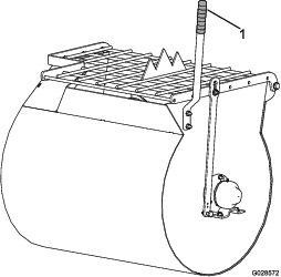
Installing the Dump Handle to the Drum
-
Cut the cable ties to remove the dump handle from the underside of the grate.
-
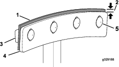
Position the dump handle so that the bolt holes align with the bolt holes in the drum (Figure 3).
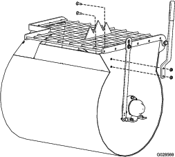
-
Insert 1 carriage bolt into the square bolt hole and slide the corresponding hole of the drum handle over it(Figure 3).
-
Install a nut onto the bolt, and tighten it.
-
Repeat the previous steps for the remaining carriage bolt.
Installing the Tow Pole
Parts needed for this procedure:
| Tow pole kit (sold separately) | 1 |
Installing the Tow Pole to the Machine
Note: The tow pole is purchased separately and includes the nut and bolt needed for installation.
The machine has the following tow pole options:
| Hitch Type | Length |
|---|---|
| 50 mm (2 inch) ball—stamped | 78.7 cm (31 inches) |
| 50 mm (2 inch) ball—forged | 78.7 cm (31 inches) |
| Pintle | 78.7 cm (31 inches) |
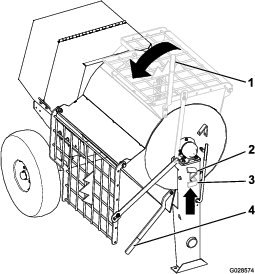
-
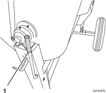
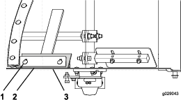
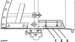
Remove the bolt and nut from the tow pole (Figure 4).
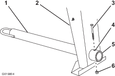
-
Slide the tow pole forward and align the hole in the pole with the hole in the frame fitting (Figure 4).
-
Insert the bolt through the holes in the fitting and the pole (Figure 4).
-
Thread the nut onto the bolt and tighten them until they are tight against the frame fitting (Figure 4).
Note: If the self-locking nylon insert in the locknut wears with use, replace the nut with a new Grade 5 or Grade 8 locknut.
Installing the Safety Chain
Parts needed for this procedure:
| Safety chain (sold with optional tow pole kit) | 1 |
| Connecting link (sold with optional tow pole kit) | 2 |
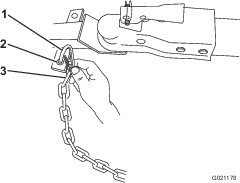
Installing the Safety Chain
Note: The safety chain is part of the optional tow pole kit.
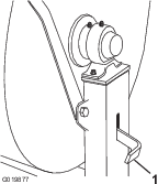
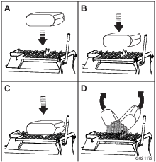
-
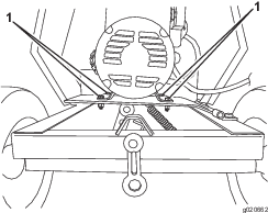
Form a hook on the end of a bendable piece of rod or stiff wire (not included), and insert it through both keyholes in the front post of the machine (Figure 5A).
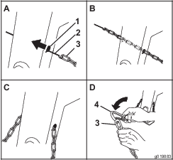
-
Attach the safety chain to the length of rod or wire (Figure 5A).
-
Pull the rod, or wire, and the safety chain through both keyholes (Figure 5B).
Note: Ensure that approximately equal lengths of safety chain extend from either side of the front post.
Installing the Connecting Links
Note: The connecting links are part of the optional tow pole kit.
-
Align the connecting link to the last link in one end of the safety chain (Figure 5D).
-
Insert the connecting link through the chain link until the connecting link snaps closed.
-
Repeat steps 1 and 2 to install the other connecting link in the other end of the safety chain.
Adjusting the Mixing Paddles
If the mixing paddles and wipers need adjustment, adjust the paddles and wipers; refer to Adjusting the Paddles.
Product Overview
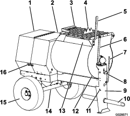
Become familiar with all the controls before you start the motor and operate the machine.
Clutch Lever
The clutch lever is used to engage and disengage motor power to the paddles.
Drum Latch
The drum latch secures the drum to the mix position (upright) for mixing operations and when transporting the machine.
Dump Handle
Use the dump handle to rotate the drum to the dump position and to rotate the drum to the mix position (upright).
Voltage Block
Use the voltage block to set the operating voltage for the machine (Figure 10).
Motor Controls
The following motor controls are found on all models:
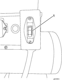
Motor
The ON/OFF switch (Figure 12) allows the operator of the machine to start and stop the motor. This switch is located on the front of the motor. It is marked (ON) and (OFF). Rotate the ON/OFF switch to the ON position to start and run the motor. Rotate the ON/OFF switch to the OFF position to stop the motor.
Note: Specifications and design are subject to change without notice.
| Model | 60212 | 60218 | 60219 |
|---|---|---|---|
| Batch Capacity | 0.17 cubic m (6.0 cubic ft) | 0.23 cubic m (8.0 cubic ft) | 0.23 cubic m (8.0 cubic ft) |
| Total Volume | 0.20 cubic m (7.1 cubic ft) | 0.25 cubic m (9.0 cubic ft) | 0.25 cubic m (9.0 cubic ft) |
| Length (without tow pole) | 150 cm (59 inches) | 168 cm (66 inches) | 168 cm (66 inches) |
| Width | 86 cm (34 inches) | 86 cm (34 inches) | 86 cm (34 inches) |
| Height | 142 cm (56 inches) | 142 cm (56 inches) | 142 cm (56 inches) |
| Weight | 250 kg (550 lb) | 275 kg (605 lb) | 275 kg (605 lb) |
| Axle | 86 to 117 cm (34 to 46 inches)extendable | 86 to 117 cm (34 to 46 inches)extendable | 86 to 117 cm (34 to 46 inches)extendable |
| Motor | 1.5 hp Baldor Electric | 1.5 hp Baldor Electric | 2 hp Baldor Electric |
Operation
Important: Before operating, remove any debris from the machine. Ensure that the area is clear of people.
Preparing to Tow the Machine
Important: Ensure that your tow vehicle has towing capacity for the weight of the machine.
Important: Use a Class 2 or larger receiver.
Note: Ensure that your tow vehicle has the appropriate hitch to tow the machine; options include a 50 mm (2 inch) ball hitch or a pintle hitch.
Note: If the machine is equipped with a trailer-light kit, ensure that the electrical connector of the tow vehicle is compatible with the electrical connector of the machine. The machine uses a standard 4-flat plug. If your tow vehicle has a different type of plug, obtain an adapter from an automotive parts store.
-
Stop the motor, unplug the machine, and empty the drum.
-
If the drum has accumulated any water, dump the drum; refer to Dumping the Drum, steps 1, 3, 4, and 5.
-
Using the dump lever, position the drum so that it is in the mix position (upright) and locked.
-
Close the cowl and secure the cowl latches (Figure 13).
-
Extend the axle; refer to Extending the Axle.
Checking the Tires and Wheels
Warning
Failure to maintain correct tire pressure may result in tire failure and loss of control, resulting in property damage and serious injury or death.
-
Check the tire pressure frequently to ensure proper inflation. If the tires are not inflated to the correct pressure, they will wear prematurely.
-
Inspect the tire condition before towing and after any operating accident.
The DOT tire information is located on the side of each tire. This information gives load and speed ratings. Replacement tires should have the same or better ratings. For more information go to http://www.nhtsa.gov/Vehicle+Safety/Tires.
Note: The various machines in this manual have different weights; refer to Specifications to ensure that the tires on your machine meet or exceed the weight requirements of your machine.
-
Visually inspect the tires for damage and wear (Figure 14 and Figure 15).
-
Ensure that the tires are inflated to the correct air pressure. The following Tire Air Pressure table shows the appropriate air pressure for the tires as installed at the factory.
Important: Always check the information on the actual tires for the correct air pressure requirement.
Important: The most common cause of tire trouble is under-inflation. Maintain full air pressure.
Tire Air Pressure
Model Tire pressure 68012 Max 414 kPa (60 psi) 68018, 68019 Max 241 kPa (35 psi) -
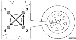
Ensure that the wheel lug nuts are torqued to 108 to 122 N-m (80 to 90 ft-lb).
Note: Check the torque of the wheel lug nuts initially and after towing.
Note: Torque the lug nuts in the sequence shown in Figure 16.
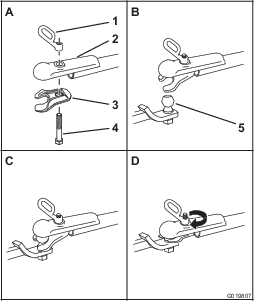
Hitching a Machine with a Stamped Ball Coupler
-
Apply chassis grease to the socket of the coupler and the area of the clamp that contacts the ball. Oil the pivot points and sliding surfaces of the coupler with SAE 30 motor oil.
-
Open the coupler latch (Figure 17).
-
Position the coupler on top of the hitch ball (Figure 17).
-
Close the coupler latch (Figure 17).
-
Open the bail on the safety pin and insert the pin through the hole in the latch (Figure 17).
-
Rotate the free end of the bail over the end of the safety pin that is protruding through the latch (Figure 17).
-
If the machine is equipped with a trailer-light kit, connect the wire plug of the tow vehicle to the wire plug of the machine.
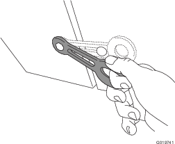
Hitching a Machine with a Forged Ball Coupler
-
Apply removable thread-locking compound to the threads of the coupler bolt to prevent the coupler handle from coming loose (Figure 18).
Important: Apply thread-locking compound as needed in the future.
-
Apply chassis grease to the socket of the coupler and the area of the clamp that contacts the ball.
-
Push the coupler bolt up through the coupler clamp and the coupler top, and connect the coupler handle to the bolt (Figure 18).
-
Position the coupler so the socket is on top of the hitch ball and the clamp is under the ball.
-
Turn the coupler handle clockwise to thread it onto the bolt until it is secure (Figure 18).
Note: Use a wrench to keep the bolt from spinning.
-
If the machine is equipped with a trailer-light kit, connect the wire plug of the tow vehicle to the wire plug of the machine.
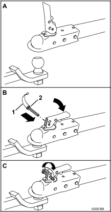
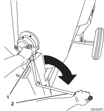
Hitching a Machine with a Pintle Hitch Tow Pole
-
Remove the pin from the pintle hitch and open it (Figure 19).
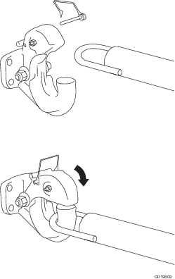
-
Position the ring on the tow pole onto the hook of the pintle hitch (Figure 19).
-
Close the top of the pintle hitch and secure it with the pin (Figure 19).
-
If the machine is equipped with a trailer-light kit, connect the wire plug of the tow vehicle to the wire plug of the machine.
Connecting the Safety Chains to the Tow Vehicle
Connect the safety chain to the machine and the tow vehicle as follows:
-
Pull the safety chain through the slots in the keyholes located in the front post of the machine, so that there is just enough slack on each side for turning around corners when towing the machine (Figure 20).
Note: Stow the excess chain inside the bottom of the front post by pushing it into the keyholes and latching the appropriate links into the keyhole slots.
-
Cross both lengths of chain under the tow pole.
Note: Crossing the chains decreases the chances of the front of the machine dropping to the ground if the hitch does not hold the connection.
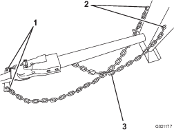
-
Connect each length of chain to the safety chain mounting point on the tow vehicle with the connecting links (Figure 21).
Extending the Axle
Warning
The machine is not stable when towing it with the axle in the narrow position.
Tow the machine with the axle in the wide position.
Important: Adjust the axle to the narrow position only to move the machine through a narrow access point, such as the gate of a fence or the doorway of a building.
Preparing to Change the Axle Width
-
Move the machine to a level job-site surface.
-
Disconnect the machine from the tow vehicle.
-
Chock the tires.
-
Ensure that the drum is empty and in the mix position (upright).
-
Ensure that the drum latch is engaged and that the drum does not rotate toward the dump position.
Adjusting the Axle Width
Warning
Mechanical or hydraulic jacks may fail to support the machine and cause serious injury.
Use jack stands when supporting the machine.
-
Align a jack with an adequate lift height and weight capacity under the axle; refer to Specifications.
-
Lift the machine until the tires are off the ground.
-
Use a jack stand at each support point on the rear frame extension (Figure 22).
-
Remove the bolts and nuts that secure the inner axle to the outer axle (Figure 23).
-
Align the inner axle to the desired position as follows:
-
Align the holes of the inner axle with the holes of the outer axle.
-
Insert the bolts through the axle holes (Figure 23).
-
Thread the nuts onto the bolts, and torque the nuts to 87 N-m (64 ft-lb).
Towing the Machine
Warning
Towing the machine at high speed increases the risk of a hitch malfunction and tire failure. Higher speeds also increase the momentum of the machine and braking distance. If the machine becomes detached from the tow vehicle at high speed, it could cause damage to property, or injury or death to bystanders.
Do not exceed 88 km/h (55 mph) when towing the machine. For poor road conditions or inclement weather, reduce speed accordingly.
Warning
Towing the machine with material in the drum increases the risk of a hitch malfunction and tire failure. In addition, material could bounce out of the drum and hit other vehicles and/or people. Material in the drum increases the weight, which affects momentum and braking distance.
Do not tow the machine with material in the drum.
-
Review and understand Safe Operating Practices.
-
Test the brakes of the tow vehicle before towing.
-
Avoid sudden starts and stops while towing the machine.
Preparing to Use the Machine
-
Review all of the safety decals on the machine.
-
Use a hard-hat, hearing protection, a shirt with long sleeves that are tight at the wrists, tight-fitting gloves without draw strings or loose cuffs, eye protection, and a dust mask or respirator. A mesh visor alone does not provide sufficient eye protection; supplement with protective glasses.
-
Ensure that you are familiar with the safety regulations and shutdown procedures described in the Operator’s Manual.
-
Ensure that all guards are in place and in good condition.
-
Ensure that the paddles are in place and in good condition.
-
Check all the grease fittings to ensure that the machine is properly lubricated.
-
When preparing to mix material:
-
Move the machine to a level job-site surface.
-
Remove the machine from the tow vehicle.
-
Chock the front and back of the tires to prevent the machine from moving.
-
Ensure that the drum is in the mix position (upright).
-
Ensure that the drum latch is engaged and that the drum does not rotate toward the dump position.
-
Opening and Closing the Cowl
Opening the Cowl
-
At the side of the machine where the front cowl and rear cowl meet, grasp the latch and pull it off from the latch anchor on the rear cowl (Figure 24).
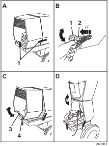
-
Repeat step 1 on the opposite side of the machine.
-
At the back of the machine where the rear cowl meets the frame of the machine, grasp the latch and pull it off from the latch anchor on the cowl (Figure 24).
-
Rotate the rear cowl up and forward until it is fully positioned on top of the front cowl (Figure 24).
Closing the Cowl
-
Rotate the rear cowl rearward and down until the receiver at the bottom center of the cowl is aligned with the V-fitting and flush on the frame of the machine (Figure 24).
-
At the back of the machine, grasp the latch and pull it onto the latch anchor on the rear cowl.
-
At the side of the machine, grasp the latch and pull it onto the latch anchor on the rear cowl.
-
Repeat step 3 at the opposite side of the machine (Figure 24).
Powering the Machine
Setting the Operating Voltage
The machine can operate with a 115 V or 230 V supply voltage. The voltage block determines the operating voltage of the machine (Figure 10). Use the following steps to change the operating voltage:
-
Park the machine on level ground.
-
Stop the motor and unplug the machine.
-
Remove the 2 screws securing the voltage block to the motor.
-
Remove the voltage block from the motor, rotate the voltage block 180 degrees and plug it back into the motor.
-
Secure the voltage plug to the motor with the 2 screws that you previously removed.
Note: Use the instructions on the voltage block to determine the voltage block setting.
Connecting to a Power Source
Danger
Contact with water while operating the product could cause electric shock, causing injury or death.
-
Do not handle the plug or the machine with wet hands or while standing in water.
-
Use only an extension cord recommended for outdoor cold-weather use.
Important: Check the extension cord frequently during use for holes or cracks in the insulation. Do not use a damaged cord. Do not run the cord through standing water or wet grass.
Important: Use only extension cords with terminals and sockets for the live, neutral, and ground wires.
Important: Connect the machine to only a receptacle with live, neutral, and ground connections.
Important: The connecting wires or extension cord should be as short as possible and in 1 piece.
To reduce the risk of electric shock, this machine has a polarized plug (unique blade shapes and widths). Use only a polarized plug and socket that is compliant with NEMA specifications and an extension cord that is UL-listed (CSA certified in Canada) and recommended for outdoor use. A polarized plug will fit in a polarized cord only 1 way. If the plug does not fit fully into the cord, turn the cord. If it still does not fit, purchase an appropriate extension cord. If you have a polarized extension cord and the extension cord plug does not fit fully into the wall receptacle, turn the plug. If it still does not fit, contact a qualified electrician to install the proper outlet. Do not change the machine plug or extension-cord plug in any way.
Note: The machine uses a twist-locking plug.
| Length | Wire Gauge |
| 15.2 m (50 ft) | 10 AWG |
| 22.8 m (75 ft) | 10 AWG |
| 30.4 m (100 ft) | 8 AWG |
Note: Do not use an extension cord over 30.4 m (100 ft) long.
Powering the Machine with a Portable Generator
When using a portable generator as an electrical source, ensure the following power output specifications:
| Model | Voltage | Amperes | Kilowatt hour | Frequency/phase |
|---|---|---|---|---|
| 68012 | 115 V /230 V | 19 A /9.5 A | 2.2 to 2.3 Kw | 60 Hz /single |
| 68018 | 115 V /230 V | 19 A /9.5 A | 2.2 to 2.3 Kw | 60 Hz /single |
| 68019 | 115 V /230 V | 24 A /12 A | 2.2 to 2.3 Kw | 60 Hz /single |
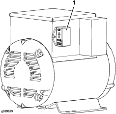
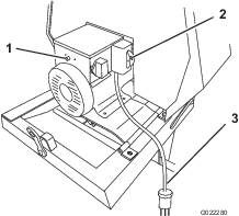
Resetting the Motor
The electrical motor for the machine is equipped with a device for thermal-overload protection. In the event that the motor shuts down automatically, reset the thermal-overload protector as follows:
-
Move the ON/OFF switch to the OFF position; refer to Figure 12.
-
Disconnect the electrical plug for the machine from the power source (Figure 25).
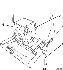
-
Allow the electric motor of the machine to cool until it is warm to the touch or cooler.
Important: Ensure that the paddles spin freely. Check for stone, masonry, or concrete material between the paddles and the drum.
-
On the side of the junction box for the motor, press the reset button for the thermal-overload protector (Figure 25).
-
Connect the electrical plug for the machine to the power source.
-
Rotate the ON/OFF switch to the ON position and ensure that the motor starts normally.
-
Rotate the ON/OFF switch to the OFF position.
Starting and Stopping the Motor
Starting the Motor
-
Plug the power cord into a proper electrical outlet.
-
Switch the ON/OFF switch to the ON position.
-
Move the clutch lever to the ON position; refer to Controlling the Paddles
Stopping the Motor
Warning
In an emergency situation, stop the motor immediately.
-
Move the clutch lever to the OFF position; refer to Controlling the Paddles.
-
Switch the ON/OFF switch to the OFF position; refer to Motor On/Off Switch.
-
Unplug the power cord.
Controlling the Paddles
Danger
This machine is capable of amputating hands.
-
Stay in the operator’s position while the machine is running.
-
Keep all bystanders a safe distance from the machine.
-
Stop the machine immediately if any people or animals enter the work area.
-
Never place any part of your body into a position that causes an unsafe operating condition.
Important: Ensure that the paddles do not turn when the clutch lever is in the OFF position.
Use the clutch lever to control the power transmission to the paddles of the machine.
Using the Clutch Lever
Move the clutch lever clockwise to engage the clutch, and counterclockwise to disengage the clutch (Figure 26).
Mixing the Material
Danger
Eye and skin contact with concrete materials and breathing the dust involved is hazardous to your health.
-
Ensure that there is adequate air ventilation.
-
Wear a dust mask to prevent inhalation of dust while using the machine; refer to Safe Operating Practices.
-
Avoid direct contact of cement and concrete materials with skin and eyes.
Danger
Contact with the mixing paddles could cause damage or injury.
Never put your hands inside the drum at any time.
Important: Do not add more material than the batch capacity of the machine; refer to Specifications.
Note: Follow the manufacturer’s instructions that are printed on the packaging of the product you are using.
Mixing a Batch of Material in the Machine
-
Ensure that there is no old, loose material in the drum that can contaminate the batch of material; refer to Cleaning the Drum and Dumping the Drum, then return the drum to the upright position.
Note: Ensure that the drum is in the mix position (upright) and the drum latch is engaged.
-
Move the clutch lever to the OFF position; refer to Controlling the Paddles.
-
Start the motor; refer to Starting the Motor.
-
Move the clutch lever to the ON position; refer to Controlling the Paddles.
-
Add the ingredients for the batch as follows:
-
Pour water into the drum through the grating of the drum guard.
-
Add the plaster, cement, or other binding material.
Note: You can open bags of cement, plaster, and binding materials by lowering the bag onto the bag splitter (Figure 27).
-
If you are using sand and/or other reinforcing materials, add them into the drum.
-
-
Allow the paddles to mix the material until the ingredients have a uniform appearance.
Note: If needed, add water or plaster, cement, or other binding material until the consistency of the batch is correct.
-
Release the drum latch and dump the drum; refer to Dumping the Drum.
Using the Drum
Danger
Contact with the mixing paddles could cause damage or injury.
Never put your hands inside the drum at any time.
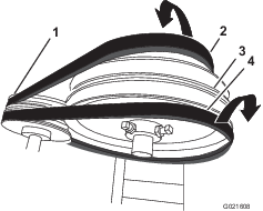
Dumping the Drum
Note: When dumping a batch of material, leave the motor running and the clutch in the ON position so the rotating paddles help discharge the material.
-
Align a wheelbarrow or similar container of adequate capacity in the path of the drum opening.
-
Grasp the dump handle with your left hand (Figure 28).
Note: When dumping a batch of material, align a wheelbarrow or a similar container of adequate capacity beneath the chute.
-
Lift the handle of the drum latch (Figure 28).
-
With both hands on the dump handle, rotate it counterclockwise to discharge the contents of the drum (Figure 28).
Note: Allow the machine to completely discharge the contents of the drum.
-
Rotate the dump handle clockwise until the drum latch locks the drum in the upright position (Figure 28).
-
After discharging a batch of material, clean the drum; refer to Cleaning the Drum.
Note: This step will clean the paddles and drum between batches and prevent dried material from forming, and contaminating the next batch of material.
Cleaning the Drum
| Maintenance Service Interval | Maintenance Procedure |
|---|---|
| After each use |
|
Important: Do not strike on the drum with a shovel, hammer, or any other device to loosen any accumulated dried materials.
-
Stop the rotation of the paddles by moving the clutch lever to the OFF position; refer to Controlling the Paddles.
-
Move the motor ON/OFF switch to the OFF position; refer to Motor On/Off Switch.
-
Ensure that the drum is in the mix position (upright); refer to Dumping the Drum, step 5.
-
Spray the machine with water to remove any accumulated material.
-
Start the motor; refer to Starting the Motor.
-
Start the rotation of the paddles by moving the clutch lever to the ON position; refer to Controlling the Paddles.
-
Dump the drum; refer to Dumping the Drum.
Maintenance
Important: Before performing any maintenance procedures, first stop the motor, wait 5 minutes to allow all moving parts to come to a complete stop and cool, and unplug the power cord.
Recommended Maintenance Schedule(s)
| Maintenance Service Interval | Maintenance Procedure |
|---|---|
| After the first 10 hours |
|
| After the first 25 hours |
|
| Before each use or daily |
|
| After each use |
|
| Every 40 hours |
|
| Every 50 hours |
|
| Every 6,000 hours |
|
| Monthly |
|
| Every 2 years |
|
Pre-Maintenance Procedures
Preparing the Machine for Maintenance
-
Park the machine on a level surface.
-
Remove the machine from the tow vehicle.
-
Chock the tires.
-
Open the rear cowl; refer to Opening the Cowl.
-
Turn off and unplug the motor; refer to Stopping the Motor.
-
Ensure that the motor is cool.
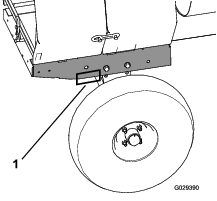
Removing and Installing the Divider Plate
You need to remove the divider plate to provide access before performing some maintenance procedures.
Removing the Divider Plate
-
Unlatch and open the cowl; refer to Opening the Cowl.
-
Use a wrench to remove the 4 bolts that secure the divider plate to the front cowl.
Note: Keep the bolts for installing the divider plate.
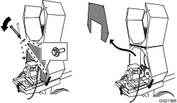
-
To remove the divider plate, lift it upward and rotate it counterclockwise so that it clears various components.
Installing the Divider Plate
-
Guide the divider plate into position against the front cowl.
Note: Start with the divider plate rotated slightly counterclockwise, and then rotate it clockwise while lowering it into position.Ensure that the divider plate is not backward.
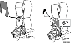
-
Align the bolt holes in the divider plate and the front cowl.
-
Install each of the 4 bolts, and hand-tighten them to prevent cross-threading.
-
Tighten the bolts with a wrench until they are secure.
Lubrication
Lubricating the Bearings and Seals
| Maintenance Service Interval | Maintenance Procedure |
|---|---|
| After each use |
|
| Monthly |
|
Note: The pillow-block bearings are inside the cowl—remove the divider plate to access them; refer to Removing the Divider Plate.
Grease type: #2 general-purpose lithium-based grease.
-
Clean around each grease fitting with a rag and lift the plastic cap off the grease fitting (Figure 31).
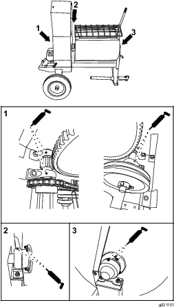
-
Pump grease into each fitting as follows:
-
For the pillow-block bearings, pump 1 shot of grease into each fitting (Figure 31).
-
For the trunnions, pump several shots of grease into each fitting until it starts to ooze out of the bearing housing (Figure 31).
Important: Pump grease in slowly and carefully to prevent damage to the bearing seals.
-
-
Wipe up any excess grease.
Lubricating the Motor Bearings
| Maintenance Service Interval | Maintenance Procedure |
|---|---|
| Every 6,000 hours |
|
Grease type: electric-motor bearing grease
-
Clean around each grease fitting with a rag.
-
Pump 1 or 2 shots of grease into each fitting (Figure 32).
Important: Do not over-lubricate the motor.
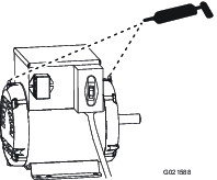
-
Wipe up any excess grease.
Lubricating the Drive Chain
| Maintenance Service Interval | Maintenance Procedure |
|---|---|
| Every 40 hours |
|
Apply a chain lubricant that is non-sticky to help prevent dirt and abrasive particles from sticking to the chain.
Belt Maintenance
Servicing the Belts
Inspecting the Belts
| Maintenance Service Interval | Maintenance Procedure |
|---|---|
| After the first 25 hours |
|
| Every 40 hours |
|
-
Remove the divider plate; refer to Removing the Divider Plate.
-
Move the clutch lever to the OFF position; refer to Controlling the Paddles.
-
Examine the belts for wear or damage. If the belts are worn or damaged, replace them; refer to Replacing the Belts.
-
Examine the pulleys for wear, damage, and misalignment; refer to Aligning the Pulleys.
-
Install the divider plate; refer to Installing the Divider Plate.
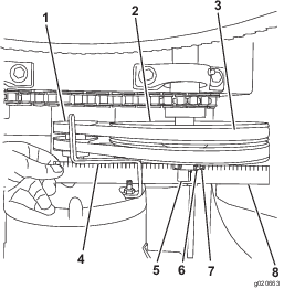
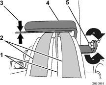
Adjusting the Belt Tension
Clutch air gap: 2.5 to 6.5 mm (3/32 to 1/4 inch)
-
Move the clutch lever to the ON position; refer to Controlling the Paddles.
-
Measure the air gap between the motor deck and the roller on the clutch (Figure 34).
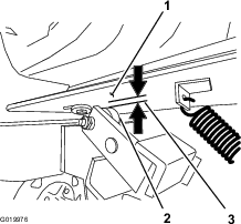
-
If the measured air gap is not within the specified range, adjust the gap as follows:
-
Move the clutch lever to the OFF position; refer to Controlling the Paddles.
-
Loosen the nuts and bolts that secure the motor to the motor deck (Figure 35).
-
Move the motor position as follows:
-
Align a straightedge across the motor pulley and the idler pulley (Figure 36).
-
If needed, pivot the motor on the motor deck until the motor pulley and the idler pulley are aligned to the straightedge (Figure 36).
-
Tighten the nuts and bolts that secure the motor to the motor deck to a torque of 18 N-m (13 ft-lb).
-
Check the air gap between the motor deck and the roller on the clutch. If the air gap is not within the specified range, repeat step 3 until the air gap measurement is within the specified range.
-
Install the divider plate; refer to Installing the Divider Plate.
-
Important: Ensure that the paddles do not rotate when the clutch lever is in the OFF position.
Replacing the Belts
| Maintenance Service Interval | Maintenance Procedure |
|---|---|
| Every 2 years |
|
Removing the Belts
-
Move the clutch lever to the OFF position; refer to Controlling the Paddles.
-
Remove the divider plate; refer to Removing the Divider Plate.
-
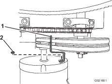
Remove the nut that secures the belt guide to the motor, and remove the belt guide (Figure 37).
-
Slip the forward belt forward and off the idler pulley (Figure 38).
-
Slip the rear belt rearward and off the idler pulley (Figure 38).
-
Slip the belts off the motor pulley.
-
Remove the belts from the machine.
Installing the Belts
-
Ensure that the clutch lever is in the OFF position; refer to Controlling the Paddles.
-
Align the rear belt to the rear groove in the motor pulley.
Note: Do not align the rear belt to the idler pulley.
-
Align the forward belt to the forward groove of the idler pulley.
-
Slip the rear belt over the idler pulley and align the belt to the rear pulley groove.
-
Slip the forward belt over the motor pulley and align the belt to the forward pulley groove.
-
Check the belt tension; refer to step 1, step 2, and step 3 in Adjusting the Belt Tension.
-
Loosely secure the belt guide to the motor (Figure 37) with the bolt that was removed in step 3 of Removing the Belts.
-
Adjust the belt guide; refer to Adjusting the Belt Guide.
-
Install the divider plate; refer to Installing the Divider Plate.
Adjusting the Belt Guide
Note: To access the belt guide, remove the divider plate; refer to Removing the Divider Plate.
Guide air gap: 2.5 to 4.0 mm (3/32 to 5/32 inch)
-
Ensure that the clutch lever is in the ON position; refer to Controlling the Paddles.
-
Ensure that the belt tension is correct; refer to Adjusting the Belt Tension.
-
Check that the air gap between the belt guide and the belts is 2.5 to 4.0 mm (3/32 to 5/32 inch); refer to Figure 39.
-
If the air gap is not within the specified range, do the following:
-
Loosen the nut that secures the belt guide to the motor (Figure 39).
Important: Ensure that the belt guide is toward the motor pulley.
-
Rotate the belt guide up or down until there is an air gap of 2.5 to 4.0 mm (3/32 to 5/32 inch) between the guide and each belt (Figure 39).
Important: The belt guide should not contact the belts with the clutch lever in the ON position.
Note: If the air gap between the belt guide and both belts cannot be attained, then 1 of the belts is too long.
-
Tighten the nut that secures the belt guide to the motor (Figure 39).
-
Check the clutch operation; refer to Checking the Clutch Operation.
-
-
Install the divider plate; refer to Installing the Divider Plate.
Checking the Clutch Operation
| Maintenance Service Interval | Maintenance Procedure |
|---|---|
| Every 40 hours |
|
Important: The paddles must not rotate in an empty drum when the clutch lever is in the OFF position.
-
Move the clutch lever to the OFF position; refer to Controlling the Paddles.
-
Start the motor; refer to Starting the Motor.
-
If the paddles rotate with the clutch lever to the OFF position do the following:
-
Stop the motor; refer to Stopping the Motor.
-
Check the air gap between the belt guide and the belts.
Note: If the air gap is larger than 4.0 mm (5/32 inch), decrease the gap between the belt guide and the belts; refer to Adjusting the Belt Guide.
-
-
Repeat steps 1, 2, and 3 until the following conditions are met:
-
The clutch lever is in the OFF position.
-
While the motor is running, the paddles do not rotate in an empty drum.
-
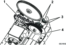
Aligning the Pulleys
-
Remove the divider plate; refer to Removing the Divider Plate.
-
Place a straightedge across the face of the motor pulley and the idler pulley (Figure 40).
Note: Both pulleys must be aligned flush with the straightedge.
-
If the pulleys are not aligned do the following:
-
Move the clutch lever to the OFF position.
-
Loosen the locknuts and setscrews that secure the idler pulley to the idler shaft (Figure 40).
-
Using a soft-face mallet, tap the idler pulley forward or backward along the idler shaft until the motor pulley and the idler pulley are aligned to the straightedge (Figure 40).
-
Tighten the setscrews and locknuts that secure the idler pulley to the idler shaft (Figure 40).
-
-
Install the divider plate; refer to Installing the Divider Plate.
Drive Chain Maintenance
Checking and Adjusting the Drive Chain
| Maintenance Service Interval | Maintenance Procedure |
|---|---|
| After the first 10 hours |
|
| Every 50 hours |
|
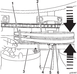
The drive chain should have 5 to 10 mm (7/32 to 13/32 inch) of flex when applying 6.8 kg (15 lb) of pressure at mid-span.
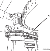
Checking the Drive-Chain Tension
-
Remove the divider plate; refer to Removing the Divider Plate.
-
Place a straightedge along the chain from 1 sprocket to the other (Figure 41).
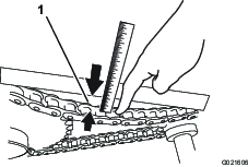
-
With your finger, push on the chain with 6.8 kg (15 lb) of pressure, midway between the sprockets (Figure 41).
-
Measure the distance from the chain to the straightedge; the distance should be 5 to 10 mm (7/32 to 13/32 inch). If the chain tension needs adjustment, refer to Adjusting the Drive-Chain Tension.
-
Install the divider plate; refer to Installing the Divider Plate.
Adjusting the Drive-Chain Tension
Note: Adjusting the tension of the drive chain affects the tension of the belts; adjust the belt tension after adjusting the drive-chain tension.
-
Remove the divider plate; refer to Removing the Divider Plate.
-
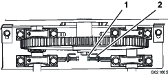
Loosen the nuts and bolts that secure the pillow-block bearings for the idler pulley (Figure 42).
-
Slide the pillow-block bearings, along with the idler pulley and small sprocket, to the right to increase the chain tension, or to the left to decrease the chain tension.
Note: To slide the pillow-block bearings to the left, you must loosen the jam nut and tensioner bolt (Figure 43). To slide the pillow-block bearings to the right, you must loosen the motor mounting nuts and bolts (Figure 35).
-
When the chain has 5 to 10 mm (7/32 to 13/32 inch) of flex, tighten the tensioner bolt, the jam nut, and the nuts and bolts that secure the pillow-block bearings.
-
Adjust the belt tension; refer to Adjusting the Belt Guide.
-
Install the divider plate; refer to Installing the Divider Plate.
Paddle Maintenance
Note: Over time, you may need to adjust the mixer paddles to account for wear.
Adjusting the Paddles
Aligning the Circumferential Drum Wipers
-
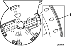
Rotate a paddle from the left row of paddles around the drum and locate at the interior of the drum the smallest distance between the drum and the wiper of the paddle (Figure 44).
-
Mark the inside of the inside of the drum at the location that you determined in step 1.
-
Align the wiper of a paddle to the mark.
-
Loosen the carriage bolts and flanged locknuts that secure the paddle blade and wiper to the paddle (Figure 45).
-
Adjust the position of the wiper so that the wiper lightly contacts the drum across the length of the wiper (Figure 46).
-
Adjust the position of the paddle blade so that the outer edge is 3 to 6 mm (1/8 to 1/4 inch) from the outer edge of the wiper.
-
Torque the carriage bolts and nuts to 19 to 25 N-m (14 to 18 ft-lb).
-
Repeat steps 4 through 7 for the other paddle for that paddle row.
-
Repeat the procedure for the other paddle rows.
Aligning the End Paddle Wipers
-
Rotate the wiper and fixed paddle around the endplate of the drum and locate smallest distance between the drum and the wiper of the paddle.
-
Mark the inside of the endplate at the location that you determined in step 1.
-
Align the wiper of a paddle to the mark.
-
Loosen the carriage bolts and flanged locknuts that secure the paddle blade and wiper to the fixed paddle. (Figure 47)
-
Adjust the position of the wiper so that the wiper lightly contacts the end plate across the length of the wiper.
-
Adjust the position of the paddle blade so that the outer edge of the bar is 3 to 6 mm (1/8 to 1/4 inch) from the outer edge of the wiper.
-
Torque the carriage bolts and nuts to 19 to 25 N-m (14 to 18 ft-lb).
-
Repeat the procedure for the wiper at the end plate on the other end of the drum.
Aligning the Adjustable End Paddles
-
Align the adjustable end paddle to the mark that you made in step 2 of Aligning the End Paddle Wipers.
-
Loosen the carriage bolts and flanged locknuts that secure the adjustable end paddle to the fixed paddle. (Figure 48)
-
Adjust the position of the adjustable end paddle so that it is as close to the end plate as possible, across the length of the paddle, without touching end plate when the paddles are rotated.
-
Torque the carriage bolts and nuts to 37 to 45 N-m (27 to 33 ft-lb).
-
Repeat the procedure for the adjustable end paddle at the end plate on the other end of the drum.
Cleaning
Cleaning the Machine
| Maintenance Service Interval | Maintenance Procedure |
|---|---|
| After each use |
|
Regular cleaning and washing will increase the life span of the machine. Clean the machine after each use, before the dirt hardens.
Ensure that the motor is unplugged.
Use care when using a high-pressure sprayer because it can damage warning decals, instruction signs, and the motor.
Important: Use pressure sprayers to clean only the drum of the machine. Clean off the rest of the machine by hand to keep the motor from getting wet.
Important: Lubricate the trunnions after cleaning; refer to Lubricating the Bearings and Seals.
Storage
Storing the Machine
For storage over 30 days, prepare the machine as follows:
-
Move the ON/OFF switch to the OFF position, and unplug the power cord.
-
Remove dirt and grime from the external parts of the entire machine, especially the motor.
Important: You can wash the machine with mild detergent and water.
-
Grease the machine; refer to Lubricating the Bearings and Seals and Lubricating the Drive Chain.
-
Check and tighten all bolts, nuts, and screws. Repair or replace any part that is damaged.
-
Paint all scratched or bare metal surfaces with paint from your Authorized Toro Dealer.
-
Store the machine in a clean, dry garage or storage area.
-
Cover the machine to protect it and keep it clean.
Troubleshooting
| Problem | Possible Cause | Corrective Action |
|---|---|---|
| The electric motor does not start. |
|
|
| The machine is humming excessively. |
|
|
| The motor is overheating. |
|
|
| The belt slips or comes off the pulleys. |
|
|
| The paddles rotate when the clutch lever is in the Off position. |
|
|
| The paddles do not rotate when the clutch lever is in the On position. |
|
|
| The paddles rotate slowly when the clutch lever is in the On position. |
|
|
| The mixer makes a chirping noise when mixing material. |
|
|
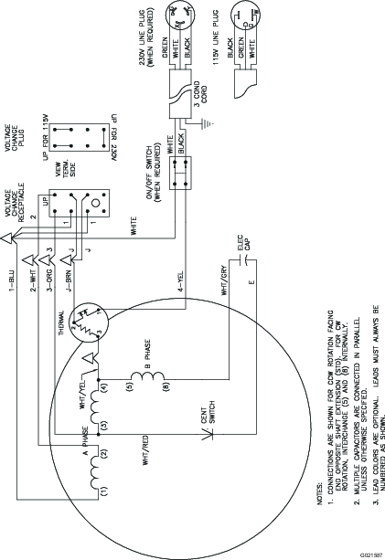
Schematics
Electric Motor Schematic