| Maintenance Service Interval | Maintenance Procedure |
|---|---|
| Before each use or daily |
|
Introduction
This machine is used to create a smooth finish to concrete slabs.
Read this information carefully to learn how to operate and maintain your product properly and to avoid injury and product damage. You are responsible for operating the product properly and safely.
You may contact Toro directly at www.Toro.com for product and accessory information, help finding a dealer, or to register your product.
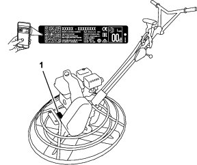
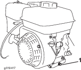
Whenever you need service, genuine Toro parts, or additional information, contact an Authorized Service Dealer or Toro Customer Service and have the model and serial numbers of your product ready. Figure 1 illustrates the location of the model and serial numbers on the product. Write the numbers in the space provided.
Important: With your mobile device, you can scan the QR code on the serial number decal (if equipped) to access warranty, parts, and other product information.
This manual identifies potential hazards and has safety messages identified by the safety alert symbol (Figure 2), which signals a hazard that may cause serious injury or death if you do not follow the recommended precautions.

This manual uses 2 words to highlight information. Important calls attention to special mechanical information and Note emphasizes general information worthy of special attention.
It is a violation of California Public Resource Code Section 4442 to use or operate the engine on any forest-covered, brush-covered, or grass-covered land without a spark arrester muffler maintained in working order, or the engine constricted, equipped, and maintained for the prevention of fire. Other states or federal areas may have similar laws. Genuine Toro spark arresters are approved by the USDA Forestry Service.
Because in some areas there are local, state, or federal regulations requiring that a spark arrester be used on the engine of this machine, a spark arrester is available as an option. If you require a spark arrester, contact your Authorized Service Dealer.
The enclosed engine owner's manual is supplied for information regarding the US Environmental Protection Agency (EPA) and the California Emission Control Regulation of emission systems, maintenance, and warranty. Replacements may be ordered through the engine manufacturer.
Warning
CALIFORNIA
Proposition 65 Warning
The engine exhaust from this product contains chemicals known to the State of California to cause cancer, birth defects, or other reproductive harm.
Use of this product may cause exposure to chemicals known to the State of California to cause cancer, birth defects, or other reproductive harm.
Safety
Improper use or maintenance by the operator or owner can result in injury. To reduce the potential for injury, comply with these safety instructions and always pay attention to the safety alert symbol, which means Caution, Warning, or Danger—personal safety instruction. Failure to comply with the instruction may result in personal injury or death.
Safe Operating Practices
This product is capable of causing serious injury. Always follow all safety instructions to avoid serious injury or death.
Warning
Engine exhaust contains carbon monoxide, an odorless, deadly poison that can kill you.
Do not run the engine indoors or in an enclosed area.
Training
-
Read the Operator's Manual and other training material. If the operator(s) or mechanic(s) cannot read or understand the information, it is the owner's responsibility to explain this material to them.
-
Become familiar with the safe operation of the equipment, operator controls, and safety signs.
-
All operators and mechanics should be trained. The owner is responsible for training the users.
-
Never let children or untrained people operate or service the equipment. Local regulations may restrict the age of the operator.
-
The owner/user can prevent and is responsible for accidents or injuries occurring people or damage to property.
Preparation
-
Wear appropriate clothing including hard hat, eye protection, long pants, substantial, slip-resistant footwear, and hearing protection. Tie back long hair, secure loose clothing, and do not wear loose jewelry.
-
Inspect the area where the equipment is to be used and ensure that all objects are removed from the area before use.
-
Use extra care when handling fuel. They are flammable and vapors are explosive.
-
Extinguish all cigarettes, cigars, pipes, and other sources of ignition.
-
Use only an approved container
-
Do not remove the fuel cap or fill the fuel tank while the engine is running or hot.
-
Do not add or drain fuel in an enclosed space.
-
Do not store the machine or fuel container where there is an open flame, spark, or pilot light, such as on a water heater or other appliance.
-
If you spill fuel, do not attempt to start the engine; avoid creating any source of ignition until the fuel vapors have dissipated.
-
-
Check that the shields are attached and functioning properly. Do not operate unless they are functioning properly.
Operation
-
Use your full attention while operating the machine. Do not engage in any activity that causes distractions; otherwise, injury or property damage may occur.
-
Never run an engine in an enclosed or poorly ventilated area.
-
Operate the machine only in good light, keeping away from holes and hidden hazards.
-
Stop on level ground, set the throttle to slow, and shut off the engine before leaving the operator's position for any reason.
-
Ensure that the area is clear of other people before operating the machine. Shut off the machine if anyone enters the area.
-
Keep bystanders out of the operating area. Stop the machine if anyone enters the area.
-
Keep your feet clear of the plate compactor.
-
Do not operate the machine while ill, tired, or under the influence of alcohol or drugs.
-
Do not change the engine governor setting or overspeed the engine.
-
Use care when loading or unloading the machine into a trailer or truck.
-
Do not touch parts which may be hot from operation. Allow them to cool before attempting to maintain, adjust, or service.
-
Lightning can cause severe injury or death. If lightning is seen or thunder is heard in the area, do not operate the machine; seek shelter.
Maintenance and Storage
-
Let the engine cool before storing and do not store the machine near an open flame.
-
Position the machine on a level surface, set the throttle to slow, and shut off the engine. Wait for all movement to stop before adjusting, cleaning, or repairing.
-
Clean debris from drives, mufflers, and the engine to help prevent fires. Clean up oil or fuel spills.
-
Do not store fuel near flames or drain indoors.
-
Never allow untrained personnel to service the machine.
-
Carefully release pressure from components with stored energy.
-
Disconnect the spark plug before making any repairs.
-
Keep hands and feet away from moving parts. If possible, do not make adjustments with the engine running.
-
Keep all parts in good working condition and all hardware tightened. Replace all worn or damaged decals.
-
Keep nuts and bolts tight. Keep equipment in good condition.
-
Stop and inspect the equipment if you strike an object. Make any necessary repairs before restarting.
-
Use only genuine Toro replacement parts to ensure that original standards are maintained.
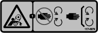
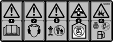
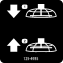
Safety and Instructional Decals
|
Safety decals and instructions are easily visible to the operator and are located near any area of potential danger. Replace any decal that is damaged or missing. |


Product Overview
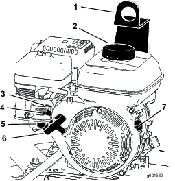
Recoil-Starter Handle
Pull the recoil-starter handle to start the engine (Figure 4).
Fuel Valve
Close the fuel valve when transporting or storing the machine (Figure 4).
Choke Lever
Use the choke lever (Figure 4) to start a cold engine. Before pulling the recoil-starter handle, move the choke lever to the closed position. Once the engine is running, move the choke lever to the open position.
Note: A warm engine requires little or no choking.
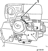
Engine On/Off Switch
The On/Off switch (Figure 4) allows the operator of the machine to start and shut off the engine. This switch is located on the front of the engine. Rotate the On/Off switch to the On position to start and run the engine. Rotate the On/Off switch to the Off position to shut off the engine.
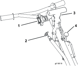
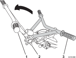
Throttle Handle
Pull the throttle handle (Figure 3) to increase the engine speed, and push the handle to decrease the engine speed. Turn the handle clockwise to lock the throttle at a specific speed. Turn the handle counterclockwise to unlock the throttle.
Handle-Adjustment Knob
Turn the knob counterclockwise to loosen and move the handle to the desired position. Turn the knob clockwise to tighten and lock the handle in place (Figure 3).
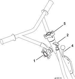
Dyna-Clutch Lever
Move the Dyna-Clutch lever (Figure 5) to the On position (up) to allow the blades to rotate. Move the lever to the Off position (down) to stop the blades. In the event that you release the handle while the blades are turning, the centrifugal force from the swing of the handle will throw the clutch lever to the Stop position.
ProPitch
Models 68049 and 68051 Only
Pull the handle to increase the angle of the blades to the concrete. Press the trip button to release the lock, and push the handle to decrease the angle of the blades.
Tilt-Adjustment Knob
Models 68048 and 68050 Only
Turn the knob clockwise to increase the angle of the blades (Figure 6). Turn the knob counterclockwise to flatten or decrease the angle of the blades.
Note: Specifications and design are subject to change without notice.
| Models | 68048 and 68049 | 68050 and 68051 |
|---|---|---|
| Width | 92 cm (36.5 inches) | 117 cm (46 inches) |
| Length (operating) | 177 cm (70 inches) | 190.5 cm (75 inches) |
| Height (operating) | 99 cm (39 inches) | 99 cm (39 inches) |
| Weight | 102 kg (225 lb) | 112 kg (245 lb) |
Attachments/Accessories
A selection of approved attachments and accessories are available for use with the machine to enhance and expand its capabilities. Contact your Authorized Service Dealer or Distributor or go to www.Toro.com for a list of all approved attachments and accessories.
Operation
Note: Determine the left and right sides of the machine from the normal operating position.
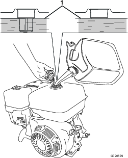
Checking the Engine-Oil Level
The machine comes from the factory with oil in the engine crankcase. However, it may be necessary to add oil. Add only enough oil to raise the level to the Full mark on the dipstick; refer to Servicing the Engine Oil.
Oil Type: 4-cycle engine oil that meets or exceeds the requirements for API service category SJ or higher
| Models | Crankcase Capacity |
|---|---|
| 68048 and 68049 | 0.58 L (0.61 US qt) |
| 68050 and 68051 | 1.1 L (1.2 US qt) |
Important: If you run the engine while the oil level in the crankcase is too low or too high, you may damage the engine.
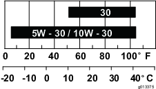
Note: Use SAE 10W-30 for general use. You can use the other viscosities shown in the chart when the average temperature in your area is within the indicated range (Figure 8).
-
Position the machine on a level surface.
-
Set the Dyna-Clutch lever to the Stop position, shut off the engine, wait for all moving parts to stop, and turn off the engine switch.
-
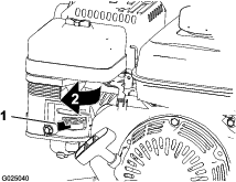
Clean around the dipstick (Figure 9) so that dirt cannot fall into the fill port and damage the engine.
-
Unscrew the dipstick and wipe the end clean (Figure 9).
-
Slide the dipstick fully into the fill port (Figure 9) without threading it into the port.
-
Remove the dipstick and look at the end. If the engine oil level is low, slowly pour only enough oil into the fill port to raise the level to the Full mark on the dipstick (Figure 9).
-
Install and secure the dipstick.
Checking the Gearcase Oil Level
| Maintenance Service Interval | Maintenance Procedure |
|---|---|
| Before each use or daily |
|
-
Position the machine on a level surface.
-
Set the Dyna-Clutch lever to the STOP position, shut off the engine, and wait for all moving parts to stop.
-
Look at the sight glass in the gearcase plug (Figure 10). The oil level should be 3/4 full.

If the oil level is not correct, refer to Servicing the Gearcase Oil.
Cleaning Debris from the Machine
| Maintenance Service Interval | Maintenance Procedure |
|---|---|
| Before each use or daily |
|
-
Set the Dyna-Clutch lever to the STOP position, shut off the engine, wait for all moving parts to stop, and shut off the engine.
-
Brush dirt and debris away from the air cleaner and engine openings.
Folding and Unfolding the Handle
-
Turn the handle-adjustment knob counterclockwise to loosen the handle.
-
Place the handle to the desired position and turn the handle-adjustment knob clockwise to tighten the handle (Figure 11).
Adding Fuel
-
For best results, use only clean, fresh (less than 30 days old), unleaded gasoline with an octane rating of 87 or higher ((R+M)/2 rating method).
-
Ethanol: Gasoline with up to 10% ethanol (gasohol) or 15% MTBE (methyl tertiary butyl ether) by volume is acceptable. Ethanol and MTBE are not the same. Gasoline with 15% ethanol (E15) by volume is not approved for use. Never use gasoline that contains more than 10% ethanol by volume, such as E15 (contains 15% ethanol), E20 (contains 20% ethanol), or E85 (contains up to 85% ethanol). Using unapproved gasoline may cause performance problems and/or engine damage which may not be covered under warranty..
-
Do not use gasoline containing methanol.
-
Do not store fuel either in the fuel tank or fuel containers over the winter unless a fuel stabilizer is used.
-
Do not add oil to gasoline.
Danger
In certain conditions, fuel is extremely flammable and highly explosive. A fire or explosion from fuel can burn you and others and can damage property.
-
Fill the fuel tank outdoors, in an open area, when the engine is cold. Wipe up any fuel that spills.
-
Never fill the fuel tank inside an enclosed trailer.
-
Do not fill the fuel tank completely full. Add fuel to the fuel tank until the level is 6 to 13 mm (1/4 to 1/2 inch) below the bottom of the filler neck. This empty space in the tank allows fuel to expand.
-
Never smoke when handling fuel, and stay away from an open flame or where fuel fumes may be ignited by a spark.
-
Store fuel in an approved container and keep it out of the reach of children. Do not use fuel that has been stored for more than 30 days.
-
Do not operate without entire exhaust system in place and in proper working condition.
Danger
In certain conditions during fueling, static electricity can be released causing a spark which can ignite the fuel vapors. A fire or explosion from fuel can burn you and others and can damage property.
-
Always place fuel containers on the ground away from your vehicle before filling.
-
Do not fill fuel containers inside a vehicle or on a truck or trailer bed because interior carpets or plastic truck bed liners may insulate the container and slow the loss of any static charge.
-
When practical, remove fuel-powered equipment from the truck or trailer and refuel the equipment with its wheels on the ground.
-
If this is not possible, then refuel such equipment on a truck or trailer from a portable container rather than from a fuel dispenser nozzle.
-
If a fuel-dispenser nozzle must be used, keep the nozzle in contact with the rim of the fuel tank or container opening at all times until fueling is complete.
Using Fuel Stabilizer/Conditioner
Use a fuel stabilizer/conditioner in the machine to keep the fuel fresh during storage of 90 days or less. If you are storing the machine for longer, drain the fuel tank; refer to Before storage.
Important: Do not use fuel additives containing methanol or ethanol.
Add the correct amount of fuel stabilizer/conditioner to the fuel, and follow the directions of the manufacturer.
Note: Fuel stabilizer/conditioner is most effective when mixed with fresh fuel. To minimize the chance of varnish deposits in the fuel system, use fuel stabilizer at all times.
Filling the Fuel Tank
| Models | Fuel Tank Capacity |
|---|---|
| 68048 and 68049 | 3.1 L (0.82 US gallons) |
| 68050 and 68051 | 5.3 L (1.40 US gallons) |
-
Set the Dyna-Clutch lever to the STOP position, shut off the engine, wait for all moving parts to stop, and turn off the engine switch.
-
Allow the engine to cool.
-
Clean around the fuel-tank cap and remove it (Figure 12).
Note: The cap is tethered to the fuel tank.
-
Add unleaded fuel to the fuel tank until the level is at the bottom of the maximum fuel level (Figure 12).
Important: The extra space in the tank allows the fuel to expand. Do not fill the fuel tank completely full.
-
Install the fuel-tank cap securely.
-
Wipe up any spilled fuel.
Starting the Engine
-
Set the throttle to full speed and set the Dyna-Clutch lever to the STOP position.
-
Move the engine switch to the ON position and turn on the fuel valve.
-
Move the choke lever to the left if you are starting a cold engine.
Note: A warm or hot engine may not require choking.
-
Pull the recoil-start handle slowly until you feel some resistance, then pull the it sharply to start the engine.
-
After the engine starts, gradually move the choke to the right. If the engine stalls or hesitates, move the choke left again until the engine warms up.
-
Move the throttle lever to desired setting.
Shutting Off the Engine
-
Reduce the engine speed to idle.
-
Turn the engine switch and fuel valve off.
-
Wait for all moving parts to stop before proceeding.
Operating the Machine
Important: Use the machine on concrete that has not set completely, but ensure that the concrete has set enough to support the weight of the machine.
-
Start the engine.
-
After the engine has warmed up, adjust the throttle to approximately half speed.
-
Adjust the blades to the desired position.
-
For floating, set the blades flat, but with some tension on the cable.
-
For finishing, set the pitch of the blades to approximately 6 to 9 mm (1/4 to 3/8 inches), or approximately 5 to 10°.
-
-
Hold the handle firmly with 1 hand, and move the Dyna-Clutch lever to the On position to start the movement of the blades.
-
Guide the trowel over the concrete in a circular back-and-forth motion.
Note: If the blades start to dig into the concrete decrease the amount of the pitch.
-
Set the Dyna-Clutch lever to the Off position, wait for any moving parts to stop moving, and shut off the engine; refer to Shutting Off the Engine.
Maintenance
Recommended Maintenance Schedule(s)
| Maintenance Service Interval | Maintenance Procedure |
|---|---|
| After the first 25 hours |
|
| Before each use or daily |
|
| Every 40 hours |
|
| Every 50 hours |
|
| Every 100 hours |
|
| Every 150 hours |
|
| Every 200 hours |
|
| Every 300 hours |
|
| Yearly or before storage |
|
Pre-Maintenance Procedures
Disconnecting the Spark-Plug Wire
Before performing any maintenance on the engine, belts, or blades, disconnect the spark-plug wire from the spark plug (Figure 13).
Lubrication
Lubricating the Blade Arms
| Maintenance Service Interval | Maintenance Procedure |
|---|---|
| Before each use or daily |
|
Grease Type: General-purpose grease.
-
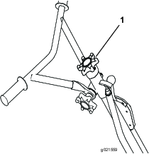
Clean around each grease fitting with a rag and lift the plastic cap off each grease fitting.
-
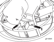
Pump several shots of grease into each fitting until it starts to ooze out of the bearing (Figure 14 and Figure 15).
Important: Pump grease in slowly and carefully to prevent damage to the bearing seals.
-
Wipe up any excess grease.
Engine Maintenance
Servicing the Air Cleaner
| Maintenance Service Interval | Maintenance Procedure |
|---|---|
| Before each use or daily |
|
| Every 50 hours |
|
| Every 300 hours |
|
Important: Do not operate the engine without the air-cleaner assembly; extreme engine damage will occur.
-
Set the Dyna-Clutch lever to the STOP position, shut off the engine, and wait for all moving parts to stop.
-
Disconnect the wire from the spark plug.
-
Remove the nut that secures the air-cleaner cover (Figure 16 Box A).

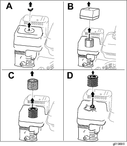
-
Remove the cover (Figure 16 Box B).
Note: Be careful to prevent dirt and debris from falling into the base.
-
Remove the foam and paper elements from the base (Figure 16 Box C).
-
Remove the foam element from the paper element (Figure 16 Box D).
-
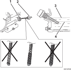
Inspect the foam and paper elements, and replace them if they are damaged or excessively dirty.
Note: Never try to brush dirt off the paper element; brushing forces the dirt into the fibers.
-
Clean the foam element in warm, soapy water or in a nonflammable solvent.
Note: Do not use fuel to clean the foam element because it could create a risk of fire or explosion.
-
Rinse and dry the foam element thoroughly.
-
Dip the foam element in clean engine oil, then squeeze out the excess oil.
Note: Excess oil in the foam element restricts the air flow through the element and may reach the paper filter and clog it.
-
Wipe dirt from the base and the cover with a moist rag.
Note: Be careful to prevent dirt and debris from entering the air duct leading to the carburetor.
-
Install the air cleaner elements and ensure that they are properly positioned.
-
Securely install the cover with the nut.
Servicing the Engine Oil
Oil Type: 4-cycle engine oil that meets or exceeds the requirements for API service category SJ or higher
| Models | Crankcase Capacity |
|---|---|
| 68048 and 68049 | 0.58 L (0.61 US qt) |
| 68050 and 68051 | 1.1 L (1.2 US qt) |
Important: If the oil level in the crankcase is too low or too high and you run the engine, you may damage the engine.
Viscosity: Use SAE 10W-30 for general use. You can use the other viscosities shown in the chart when the average temperature in your area is within the indicated range (Figure 8).
Changing the Engine Oil
| Maintenance Service Interval | Maintenance Procedure |
|---|---|
| After the first 25 hours |
|
| Every 100 hours |
|
Warning
Oil may be hot after the engine has been run, and contact with hot oil can cause severe personal injury.
Avoid contacting the hot engine oil when you drain it.
-
Position the machine on a level surface.
-
Set the Dyna-Clutch lever to the STOP position, shut off the engine, and wait for all moving parts to stop.
-
Disconnect the wire from the spark plug.
-
Place a pan under the drain plug to catch the oil.
-
Remove the drain plug (Figure 18).
-
Replace the plug when the oil has drained completely.
Note: Dispose of the used oil at a certified recycling center.
-
Remove the dipstick (Figure 9) and slowly pour oil into the fill hole until the oil is between the upper and lower fill marks on the dipstick.
-
Install and secure the dipstick.
-
Wipe up any spilled oil.
Servicing the Gearcase Oil
| Maintenance Service Interval | Maintenance Procedure |
|---|---|
| Every 150 hours |
|
Oil Type: 80W-90 gear oil that meets or exceeds API service category GL-5.
Capacity: 1.18 L (1.25 US qt)
-
Set the Dyna-Clutch lever to the STOP position, shut off the engine, and wait for all moving parts to stop.
-
Disconnect the wire from the spark plug.
-
Place a pan under the drain plug to catch the oil.
-
Remove the gearcase plug (Figure 18).
-
Tip the machine and drain the oil completely out of the gearcase.
Note: Dispose of the used oil at a certified recycling center.
-
Return the machine to an upright, level position.
-
Place a 3.8 cm (1-1/2 inch) block under the stationary blade guard (outer ring) so that the side of the gearbox with the plug is approximately 6 mm (1/4 inch) higher than the other side of the gearbox.
-
Slowly pour oil into the plug hole until the oil reaches the threads of the hole.
Note: If necessary, use a flexible funnel.
-
Apply thread-sealing compound to the threads of the plug.
-
Install and tighten the plug until it is secure, and return the machine to an upright, level position.
Note: The oil level in the sight glass of the plug should be 3/4 full (Figure 20).
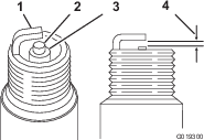
Servicing the Spark Plug
| Maintenance Service Interval | Maintenance Procedure |
|---|---|
| Every 100 hours |
|
| Every 200 hours |
|
Use an NGK BPR6ES spark plug or equivalent.
-
Set the Dyna-Clutch lever to the STOP position, shut off the engine, and wait for all moving parts to stop.
-
Disconnect the wire from the spark plug.
-
Clean around the spark plug.
-
Remove the spark plug from the cylinder head.
Important: Replace a cracked, fouled, or dirty spark plug. Do not clean the electrodes, because grit entering the cylinder can damage the engine.
-
Set the gap on the plug to 0.76 mm (0.030 inch); refer to Figure 21.
-
Carefully install the spark plug by hand (to avoid cross threading) until it is hand tight.
-
Tighten the spark plug an additional 1/2 turn if it is new; otherwise, tighten it an additional 1/8 to 1/4 turn.
Important: A loose spark plug can become very hot and can damage the engine; overtightening a spark plug may damage the threads in the cylinder head.
-
Connect the wire to the spark plug.
Belt Maintenance
Checking the Belt, Pulley Alignment, Belt Tension, and Belt-Guide Gap
| Maintenance Service Interval | Maintenance Procedure |
|---|---|
| Every 40 hours |
|
-
Remove the belt guard; refer to Removing the Belt Guard.
-
Move the Dyna-Clutch lever to the STOP position.
-
Check the condition of the belt for wear or damage.
Note: If the belt is worn or damaged, replace the belt; refer toRemoving the Belt and Installing the Belt.
-
Move the Dyna-Clutch lever to the RUN position.
-
Check that the belt is aligned straight between pulleys.
Note: If the belt does not run straight between pulleys, align the pulleys; refer to Aligning the Pulleys.
-
Check that the belt has enough tension to flatten it between the engine pulley and the belt tension pulley.
Note: If belt tension is too low, adjust the tension of the belt-tension pulley; refer to Adjusting the Dyna-Clutch.
-
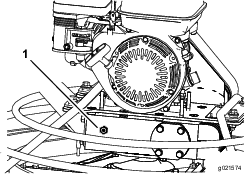
Measure the gap between the belt and the belt guide. The air gap should be approximately 6 mm (1/4 inch).
Note: If the air gap is larger or smaller than 6 mm (1/4 inch), adjust the belt guide (Figure 26); refer to Adjusting the Belt Guide.
-
Install the belt guard; refer to Installing the Belt Guard.
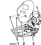
Removing the Belt Guard
Installing the Belt Guard
-
Align the holes in the belt guard with the holes in the belt-cover bracket (Figure 22).
-
Secure the belt guard to the bracket with the 2 hex-washer head bolts (5/16 x 1 inch).
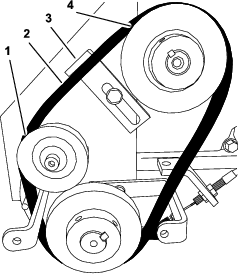
Removing the Belt
-
Position the machine on a level surface, place the Dyna-Clutch lever in the STOP position, shut off the engine, and disconnect the spark-plug wire.
-
Remove the belt guard; refer to Removing the Belt Guard.
-
Slip the belt off the belt-tension pulley (Figure 23).
-
Slip the belt off the gearbox pulley (Figure 23).
-
Slip the belt off the engine pulley and remove the belt (Figure 23).
Installing the Belt
-
Ensure the Dyna-Clutch lever in the STOP position.
-
Align the belt over the engine pulley (Figure 23).
-
Align the belt over the gearbox pulley (Figure 23).
-
Slip the belt over the belt-tension pulley (Figure 23).
-
Install the belt guard; refer to Installing the Belt Guard.
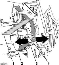
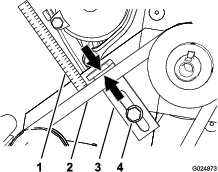
Aligning the Pulleys
-
Place a straight-edge ruler across the engine pulley and the gearbox pulley (Figure 24).
-
If the pulleys are out of alignment, perform the following steps:
-
Loosen the 2 setscrews that secure the engine pulley to the engine shaft (Figure 24).
-
Gently tap the engine pulley toward or away from the engine until the gearbox and engine pulleys align to the straight-edge ruler (Figure 24).
-
Tighten the 2 setscrews that secure the engine pulley to the engine shaft (Figure 24).
-
Adjusting the Dyna-Clutch
Important: This adjustment procedure affects the operation of the Dyna-Clutch and is critical to the safe operation of the machine.
Adjust the tension-pulley spring as needed to tighten the belt.
-
Move the Dyna-Clutch lever to the STOP position; refer to Dyna-Clutch Lever.
-
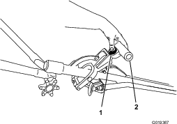
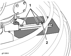
Loosen the 2 jam nuts that secure the barrel of the clutch cable to the clutch bracket, and rotate the nuts to either end of threads on the barrel (Figure 25).
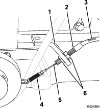
-
Grasp the barrel with 1 hand and lift the cable housing lightly (Figure 25).
Note: Lifting the cable housing at the barrel should remove the slack from the cable but apply no tension to the spring.
-
While holding tension on the cable, use your other hand, rotate the jam nuts until the nuts are flush to the clutch bracket (Figure 25).
-
Tighten the jam nuts to secure the barrel to the bracket (Figure 25).
-
Check the tension of the control cable. Repeat steps 2 through 4 until there is tension on the Dyna-Clutch cable but no tension on the spring.
Note: If there is too much tension on the cable and spring, the Dyna-Clutch will not release completely. If there is not enough tension on the cable, the cable may disconnect from the pulley bracket.
-
If you need to make a finer cable adjustment, perform the following:
-
Start the machine and set Dyna-Clutch to the RUN position for a few moments, then move the Dyna-Clutch to the STOP position.
Note: If the blades continue to rotate when the Dyna-Clutch is in the STOP position, there is too much tension on the clutch cable. Shut off the engine and repeat step 7 until the blades do not rotate when the engine is running and the Dyna-Clutch is in the STOP position.
Adjusting the Belt Guide
-
Place the Dyna-Clutch lever in the RUN position.
-
Measure the air gap between the belt and the belt guide (Figure 26).
The air gap should be approximately 6 mm (1/4 inch). If an adjustment needs to be done, perform the following:
-
Loosen the hex-flange head bolt that secures the belt guide to the engine plate (Figure 26).
-
While keeping the top of the belt guide parallel to the belt, move the belt guide toward or away from the belt until the air gap is correct (Figure 26).
-
Tighten the hex-flange head bolt that secures the belt guide to the engine plate (Figure 26).
Controls System Maintenance
Adjusting the Tilt Knob
-
Set the Dyna-Clutch lever to the Stop position, shut off the engine, and wait for all moving parts to stop.
-
Disconnect the wire from the spark plug.
-
Attach an overhead lift to the lifting point on the machine and lift it off of the ground.
-
Turn the tilt knob until there is enough cable slack to access the tilt locknut (Figure 27).
-
Tighten the locknut against the bearing then loosen it slightly. Set it with the set screw (Figure 27).
-
Adjust the nuts inside the tilt block to take up any cable slack.
Note: Replace the cables if full tilt is no longer obtainable.
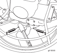
Adjusting the ProPitch Linkage Rod
-
Set the Dyna-Clutch lever to the Stop position, shut off the engine, and wait for all moving parts to stop.
-
Disconnect the wire from the spark plug.
-
Attach an overhead lift to the lifting point on the machine and lift if off of the ground.
-
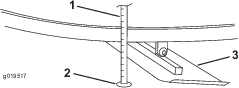
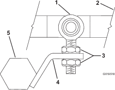
Loosen the nut on the upper end of the linkage rod to allow slack in the lift cable (Figure 28).
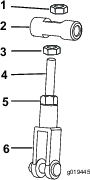
-
Position the ProPitch handle in the full tilt position.
-
Adjust the nut on the backside of the swivel at the upper end of the linkage rod until you achieve the proper gap of approximately 0.4 mm (1/64 inch) between the tilt lever and the gearcase.
-
Tighten the nut on the outside of the swivel to lock the linkage rod into position.
Testing the Dyna-Clutch Lever
Testing the Dyna-Clutch Operation
Ensure that the area is clear of any debris or bystanders before beginning the testing procedures.
-
Start the trowel, engage the Dyna-Clutch lever, and run the machine for a few moments.
-
Move the Dyna-Clutch lever to the Stop position.
-
Watch the blades for any sign of continued rotation.
If the blades do not stop, there is too much tension on the cable and spring. Shut off the engine and decrease the amount of tension to allow the Dyna-Clutch lever to disengage completely.
Ensure that there is still enough tension on the cable and spring to prevent parts from coming unhooked during operation. If the tendency for the blades to rotate when the Dyna-Clutch lever is disengaged cannot be adjusted out of the system without taking all tension off of the cable and spring, carefully inspect the drive belt and Dyna-Clutch lever system for wear or damage. Ensure that all parts are operating freely. If the Dyna-Clutch lever does not stop the blades, see an Authorized Service Dealer.
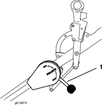
Testing the Dyna-Clutch Lever Adjustment
Important: Ensure that the testing of the Dyna-Clutch lever is done is a clear and open area.
Important: Clear the test area of bystanders.
-
Move the Dyna-Clutch lever to the STOP position; refer to Dyna-Clutch Lever.
-
Start the trowel.
-
Move the fuel valve to the OFF position (Figure 29).
Important: You must move the fuel valve to the OFF position before continuing this procedure.
-
Hold onto the handle and engage the Dyna-Clutch lever; refer to Dyna-Clutch Lever.
-
Let go of the handle.
The Dyna-Clutch lever should switch to the STOP position within 1 rotation. If it does not, keep clear of the area and wait for the machine to run out of fuel.
Note: If the Dyna-Clutch does not stop the machine within 1 rotation, adjust the Dyna-Clutch or bring the machine to an authorized service location; refer to Adjusting the Dyna-Clutch.
-
Move the Dyna-Clutch lever to the STOP position.
Adjusting the Blades
Adjust the blades to remove excessive shaking of the machine.
-
Disconnect the spark plug wire and move the Dyna-Clutch lever to the STOP position.
-
Place 3 or 4 blocks of equal height under the stationary blade guard (outer ring) to raise the blades off of the floor.
Note: Ensure that the blocks are clear of the blades so that the blades can be rotated without touching the blocks.
-
Measure from the floor to the leading edge of the blade. Note the measurement.
-
Place a mark on the blade and on the spot on the floor from where the measurement was taken (Figure 31).
-
Rotate the blades until the next blade is in the same position as the previously measured blade.
-
Measure the second blade from the spot previously marked on the floor to the second blades leading edge (Figure 32).
-
Compare the 2 measurements.
If the height of the second blade is not within 0.8 mm (1/32 inch) of the height of the first blade, adjust the second blade.
-
Loosen the locknuts on the blade (Figure 33).
-
Adjust the blade arm lever up or down as necessary to make the second blade height the same height of the first blade that was measured.
-
Tighten the locknuts.
-
Repeat as necessary for the remaining blades.
Adjusting the Blade Arms
Adjust the blade arms if the machine still shakes excessively after the blades have been adjusted.
-
Place the machine on a flat surface.
-
Disconnect the spark plug.
-
Turn the tilt adjustment knob counter clockwise until all of the tension is off of the tilt adjustment cable and the blades are flat against the floor.
Blade arms should be unbent and flat to the floor. If a blade is bent, continue this procedure to adjust the blade arm. If blades are unbent and flat to the floor, examine the machine for other worn parts.
Note: Do not screw the knob completely out of the handle.
-
Loosen the bolts 3 to 4 turns (Figure 34).
-
Loosen the locknut and tighten the outermost bolt until the blade lays flat against the floor.
-
Tighten the locknut and bolts.
-
Repeat for other blades as necessary.
If the blade arm cannot be adjusted to lay flat, replace the blade arm.
If the machine continues shaking excessively after the blade arms have been adjusted, examine the remainder of the machine for any other worn parts.
Storage
-
Set the Dyna-Clutch lever to the Stop position, shut off the engine, and disconnect the spark-plug wire.
-
Remove dirt and grime from the entire machine.
Important: You can wash the machine with mild detergent and water. Do not pressure wash the machine. Avoid excessive use of water, especially near the engine.
-
Service the air cleaner; refer to Servicing the Air Cleaner.
Change the engine oil; refer to Changing the Engine Oil.
-
For storage over 30 days, prepare the machine as follows:
-
Add a petroleum based stabilizer/conditioner to fuel in the tank. Follow the mixing instructions from stabilizer manufacturer. Do not use an alcohol-based stabilizer (ethanol or methanol).
Note: A fuel stabilizer/conditioner is most effective when mixed with fresh fuel and used at all times.
-
Run the engine until it stops from running out of fuel.
-
Choke the engine.
-
Start and run the engine until it will not start again.
-
Dispose of fuel properly. Recycle as per local codes.
Important: Do not store stabilizer/conditioned fuel over 90 days.
-
-
Check and tighten all bolts, nuts, and screws. Repair or replace any part that is damaged.
-
Paint all scratched or bare metal surfaces. Paint is available from your Authorized Service Dealer.
-
Store the machine in a clean, dry garage or storage area.
-
Cover the machine to protect it and keep it clean.
Troubleshooting
| Problem | Possible Cause | Corrective Action |
|---|---|---|
| The trowel blade turns when the recoil is pulled. |
|
|
| The trowel blades are wearing unevenly. |
|
|
| The trowel bounces, rocks, or digs into the concrete. |
|
|
| The tilt knob is difficult to turn. |
|
|
| The Dyna-Clutch lever is difficult to engage. |
|
|
| The belt slips. |
|
|
| The gearcase is emitting a grinding noise. |
|
|
| The engine does not start. |
|
|
| The engine runs rough. |
|
|