
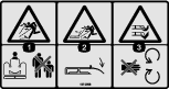
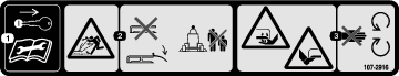
 , which means Caution, Warning,
or Danger—personal safety instruction. Failure to comply with
these instructions may result in personal injury or death.
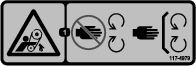
, which means Caution, Warning,
or Danger—personal safety instruction. Failure to comply with
these instructions may result in personal injury or death.


Maintenance
Recommended Maintenance Schedule(s)
| Maintenance Service Interval | Maintenance Procedure |
|---|---|
| After the first 2 hours |
|
| After the first 10 hours |
|
| Before each use or daily |
|
| After each use |
|
| Every 50 hours |
|
| Every 400 hours |
|
Lubrication
| Maintenance Service Interval | Maintenance Procedure |
|---|---|
| Before each use or daily |
|
| Every 50 hours |
|
The machine has grease fittings that must be lubricated regularly with No. 2 lithium grease. Lubricate all bearings and bushings immediately after every washing.
Lubricate the following areas:
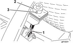
Checking the Lubricant in the Gearbox
| Maintenance Service Interval | Maintenance Procedure |
|---|---|
| Every 50 hours |
|
| Every 400 hours |
|
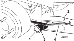
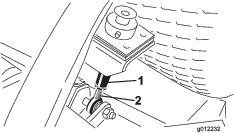
The gearbox is designed to operate on either petroleum or synthetic SAE 80W–90 gear lube. Although the gearbox is shipped with lubricant from the factory, check the level before operating the cutting unit. The gearbox capacity is 283 ml (12 oz).
-
Position the machine and cutting unit on a level surface.
-
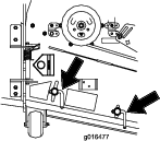
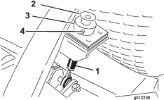
Remove the dipstick/fill plug from the top of the gearbox (Figure 22) and make sure that the lubricant is between the marks on the dipstick. If the lubricant level is low, add enough lubricant until the level is between the marks.
Separating the Cutting Unit from the Traction Unit
-
Position the machine on level surface, lower the cutting unit to the floor, move the lift lever to the FLOAT position, shut off the engine, and engage the parking brake.
-
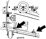
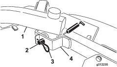
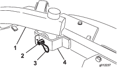
Remove the bolt and washer mounted to the top of each height of cut rod (Figure 23).
-
Remove the hairpin and clevis pin securing the height of cut collar to the height of cut rod on the rear of the cutting unit (Figure 23). Remove the height of cut collar.
-
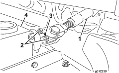
Remove the hairpin cotters and clevis pins securing the lift arms to the castor arm brackets (Figure 24).
-
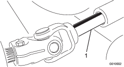
Roll the cutting unit away from the traction unit, separating the male and female sections of the PTO shaft (Figure 25).
Danger
If the engine is started and the PTO shaft is allowed to rotate, serious injury could result.
Do not start the engine and engage the PTO lever when the PTO shaft is not connected to the gearbox on the cutting unit.
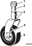
Servicing the Bushings in the Castor Arms
The castor arms have bushings pressed into the top and bottom of the tube, and after many hours of operation, the bushings wear.
To check the bushings, move the castor fork back and forth and from side to side. If the castor spindle is loose inside the bushings, the bushings are worn; replace them.
-
Raise the cutting unit so that the wheels are off of the floor. Block the cutting unit so that it cannot accidentally fall.
-
Remove the tensioning cap, spacer(s), and thrust washer from the top of the castor spindle.
-
Pull the castor spindle out of the mounting tube. Allow the thrust washer and spacer(s) to remain on the bottom of the spindle.
-
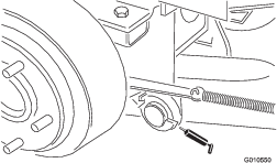
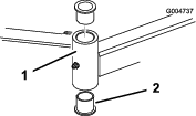
Insert a pin punch into the top or bottom of the mounting tube and drive the bushing out of the tube (Figure 26). Also, drive the other bushing out of the tube. Clean the inside of the tubes to remove dirt.
-
Apply grease to the inside and outside of the new bushings. Use a hammer and flat plate to drive the bushings into the mounting tube.
-
Inspect the castor spindle for wear and replace it if damaged.
-
Push the castor spindle through the bushings and mounting tube, slide the thrust washer and spacer(s) onto the spindle, and install the tensioning cap on the castor spindle.
Servicing the Castor Wheels and Bearings
| Maintenance Service Interval | Maintenance Procedure |
|---|---|
| After the first 2 hours |
|
| After the first 10 hours |
|
| Every 50 hours |
|
-
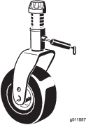
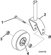
Remove the locknut from the bolt holding the castor wheel assembly between the castor fork (Figure 27). Grasp the castor wheel and slide the bolt out of the fork or pivot arm.
-
Remove the bearing from the wheel hub and allow the bearing spacer to fall out (Figure 27). Remove the bearing from the opposite side of the wheel hub.
-
Check the bearings, spacer, and inside of the wheel hub for wear. Replace any damaged parts.
-
To assemble the castor wheel, push the bearing into the wheel hub. When installing the bearings, press on the outer race of the bearing.
-
Slide the bearing spacer into the wheel hub. Push the other bearing into the open end of the wheel hub to captivate the bearing spacer inside the wheel hub.
-
Install the castor wheel assembly between the castor fork and secure it in place with the bolt and locknut.
Servicing the Cutting Blades
Blade Safety
-
Inspect the blade periodically for wear or damage.
-
Use care when checking the blades. Wrap the blades or wear gloves, and use caution when servicing the blades. Only replace or sharpen the blades; never straighten or weld them.
-
On multi-bladed machines, take care as rotating 1 blade can cause other blades to rotate.
Checking for a Bent Blade
After striking a foreign object, inspect the machine for damage and make repairs before starting and operating the equipment. Torque all of the spindle-pulley nuts to 176 to 203 N∙m (130 to 150 ft-lb).
-
Position the machine on a level surface, raise the cutting unit, engage the parking brake, put the traction pedal in NEUTRAL, put the PTO lever in the OFF position, shut off the engine, and remove the ignition key.
Note: Block the cutting unit to prevent it from accidentally falling.
-
Rotate the blade until the ends face forward and backward and measure from the inside of the cutting unit to the cutting edge at the front of the blade (Figure 28).
Note: Remember this dimension.

-
Rotate the opposite end of the blade forward and measure between the cutting unit and cutting edge of the blade at the same position as in step 2.
Note: The difference between the dimensions obtained in steps 2 and 3 must not exceed 3 mm (1/8 inch). If the dimension exceeds 3 mm (1/8 inch), the blade is bent and must be replaced; refer to Removing and Installing the Cutting-Unit Blade(s).
Removing and Installing the Cutting-Unit Blade(s)
Replace the blade if it hits a solid object, is out of balance, or is bent. Always use genuine Toro replacement blades to ensure safety and optimum performance.
-
Park the machine on a level surface, raise the cutting unit to the transport position, engage the parking brake, shut off the engine, and remove the key.
Note: Block or lock the cutting unit to prevent it from accidentally falling.
-
Grasp the end of the blade using a rag or thickly-padded glove.
-
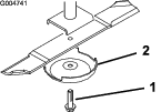
Remove the blade bolt, anti-scalp cup, and blade from the spindle shaft (Figure 29).
-
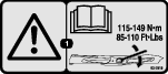
Install the blade, anti-scalp cup, and blade bolt and tighten the blade bolt to 115 to 149 N∙m (85 to 110 ft-lb).
Important: The curved part of the blade must be pointing toward the inside of the cutting unit to ensure proper cutting.
Note: After striking a foreign object, torque all spindle-pulley nuts to 115 to 149 N∙m (85 to 110 ft-lb).
Inspecting and Sharpening the Cutting Unit Blade(s)
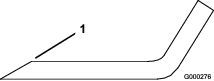
Both cutting edges and the sail, which is the turned-up portion opposite of the cutting edge, contribute to a good quality of cut.
Maintain sharp blades throughout the cutting season. Sharp blades create a clean cut without tearing or shredding the grass blades.
Check the blades for any wear or damage. The sail lifts the grass up straight, thereby producing an even cut and gradually wears down during operation.
-
Park the machine on a level surface, raise the cutting unit, engage the parking brake, put the traction pedal in NEUTRAL, put the PTO lever in the OFF position, shut off the engine, and remove the key from the ignition.
-
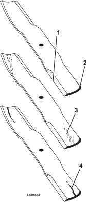
Examine the cutting ends of the blade carefully, especially where the flat and curved parts of the blade meet (Figure 30).
Note: Because sand and abrasive material can wear away the metal that connects the flat and curved parts of the blade, check the blade before using the mower. If you notice wear (Figure 30), replace the blade.
-
Examine the cutting edges of all of the blades and sharpen the cutting edges if they are dull or nicked (Figure 31).
Note: Sharpen only the top of the cutting edge and maintain the original cutting angle to ensure sharpness (Figure 31). The blade remains balanced if the same amount of metal is removed from both cutting edges.
Note: Remove the blades and sharpen them on a grinder. After sharpening the cutting edges, install the blade with the anti-scalp cup and blade bolt; refer to Removing and Installing the Cutting-Unit Blade(s).
Checking and Correcting Mismatch of Blades
If there is mismatch between the blades, the grass will appear streaked when it is cut. This problem can be corrected by making sure that the blades are straight and all of the blades are cutting on the same plane.
-
Using a 1 m (3 ft) long carpenter’s level, find a level surface on the shop floor.
-
Raise the height of cut to the highest position; refer to Adjusting the Height of Cut.
-
Lower the cutting unit onto the flat surface. Remove the covers from the top of the cutting unit.
-
Rotate the blades until the ends face forward and backward. Measure from the floor to the front tip of the cutting edge. Remember this dimension. Then rotate the same blade so that the opposite end is forward, and measure again. The difference between the dimensions must not exceed 3 mm (1/8 inch). If the dimension exceeds 3 mm (1/8 inch), replace the blade because it is bent. Make sure to measure all of the blades.
-
Compare the measurements of the outer blades with the center blade. The center blade must not be more than 10 mm (3/8 inch) lower than the outer blades. If the center blade is more than 10 mm (3/8 inch) lower than the outer blades, proceed to step 6 and add shims between the spindle housing and the bottom of the cutting unit.
-
Remove the bolts, flat washers, lock washers, and nuts from the outer spindle in the area where the shims must be added. To raise or lower the blade, add a shim, Part No. 3256-24, between the spindle housing and the bottom of the cutting unit. Continue to check the alignment of the blades and add shims until the tips of the blades are within the required dimension.
Important: Do not use more than three shims at any one hole location. Use decreasing numbers of shims in adjacent holes if more than one shim is added to any one hole location.
-
Install the belt covers.
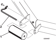
Replacing the Drive Belt
| Maintenance Service Interval | Maintenance Procedure |
|---|---|
| Every 50 hours |
|
The blade drive belt, tensioned by the spring loaded idler pulley, is very durable. However, after many hours of use, the belt will show signs of wear. Signs of a worn belt are squealing when belt is rotating, blades slipping when cutting grass, frayed edges, burn marks, and cracks. Replace the belt if any of these conditions occur.
-
Lower the cutting unit to the shop floor. Remove the belt covers from the top of the cutting unit and set the covers aside.
-
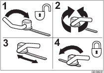
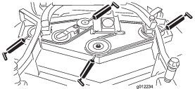
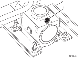
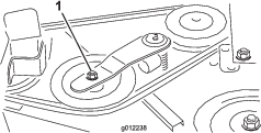
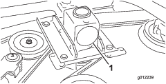
Using a torque wrench or similar tool, move the idler pulley (Figure 32) away from the drive belt to release the belt tension and allow the belt to be slipped off the gearbox pulley (Figure 33).
-
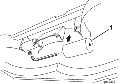
Remove the old belt from around the spindle pulleys and idler pulley.
-
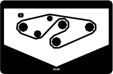
Route the new belt around the spindle pulleys and idler pulley assembly as shown in Figure 34.
-
Install the belt covers.
Replacing the Grass Deflector
Warning
An uncovered discharge opening could allow the machine to throw objects toward you or bystanders, resulting in serious injury. Also, contact with the blade could occur.
-
Do not operate the machine unless you install a cover plate, a mulch plate, or a grass chute and catcher.
-
Ensure that the grass deflector is in the down position.
-
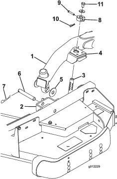
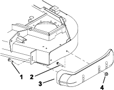
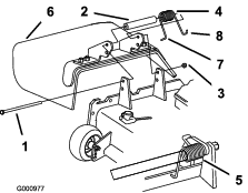
Remove the locknut, bolt, spring and spacer holding the deflector to the pivot brackets (Figure 35). Remove the damaged or worn grass deflector.
-
Place the spacer and spring onto grass deflector. Place the L-end of the spring behind the cutting unit edge.
Note: Ensure that the L-end of the spring is installed behind the cutting unit edge before installing the bolt as shown in Figure 35.
-
Install the bolt and nut. Place the J-hook end of the spring around the grass deflector (Figure 35).
Important: You must be able to lower the grass deflector into position. Lift the deflector up to test that it lowers into the full down position.
Cleaning Under the Cutting Unit
| Maintenance Service Interval | Maintenance Procedure |
|---|---|
| After each use |
|
Remove the grass buildup under the cutting unit daily.
-
Disengage the PTO, release the traction pedal to the neutral position, and engage the parking brake.
-
Move the throttle lever to the SLOW position, shut off the engine, remove the key, and wait for all moving parts to stop before leaving the operator’s position.
-
Raise the cutting unit to the TRANSPORT position.
-
Use a jack to raise the front of the machine and support it with jack stands.
-
Thoroughly clean the underside of the cutting unit with water.