Installation
Preparing the Machine
-
Park the machine on a level surface.
-
Engage the parking brake.
-
Turn the key to the OFF position and remove the key.
-
Raise the cargo bed; refer to the Operator’s Manual.
Removing the Existing Traction Motor
-
Ensure that the machine battery charger is not connected to an electrical outlet.
Open the battery circuit by disconnecting the conductors between the battery pack and machine components.
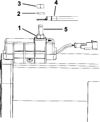
Important: When removing the cables from the motor terminals (U, V, and W), use a wrench to retain the lower nut while loosening the upper nut (Figure 1). If the terminal studs are allowed to turn during upper nut removal, internal motor damage can occur.
Note: Label all traction motor electrical leads for assembly purposes.
-
Disconnect the electrical connectors from the traction motor and position them away from the motor:
-
While retaining the lower nut to prevent it from loosening, remove the upper nut, lock washer, and cable connector from traction motor terminal studs U, V, and W (Figure 1).
-
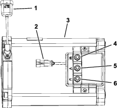
Unplug the wire harness connectors from traction motor encoder (speed sensor) and thermistor (temperature) as shown in Figure 2.
-
-
Position the disconnected cables and wire harness leads away from the traction motor.
-
Wrap a suitable lifting strap around the center of the traction motor housing for support and as a lifting point for motor removal. Ensure that you do not capture the encoder (speed sensor) or thermistor wires under the strap. Support the motor with the strap to prevent it from moving.
Caution
To prevent motor damage and personal injury, ensure that traction motor is well supported as it is removed. The motor weighs approximately 30 kg (66 lb).
-
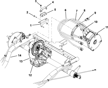
Remove the 2 flange-head screws that secure the cable bracket to the transaxle and traction motor (Figure 3).
Position the cable bracket with the attached cables away from the motor and transaxle.
-
Remove the remaining 4 flange-head screws that secure the motor to the transaxle (Figure 3).
-
Pull the motor away from the transaxle until the motor shaft is disengaged from the transaxle-input shaft (Figure 3).
-
Carefully lift the motor from the machine, and ensure that you do not damage the motor sensors or machine components while you are removing the motor.
-
If necessary, remove the washer-head screw securing the isolator retainer and isolator to the isolator bracket (Figure 3).
Separate the isolator and motor cables from the bracket.
Installing the New Traction Motor
Parts needed for this procedure:
| Traction motor | 1 |
-
If the isolator and wire cables were removed from the cable bracket, insert the cables into the isolator (Figure 3).
-
Secure the isolator and cables to the bracket using the isolator bracket and washer-head screw (Figure 3).
-
Torque the washer-head screw to 10.2 to 12.4 N∙m (90 to 110 in-lb).
-
Apply anti-seize lubricant to the splines of the transaxle and traction motor shafts (Figure 3).
-
Wrap a suitable lifting strap around the traction motor housing for support and as a lowering point for motor installation. Ensure that you do not capture the encoder (speed sensor) or thermistor wires under the strap.
Caution
To prevent motor damage and personal injury, ensure that traction motor is well supported as it is removed. The motor weighs approximately 30 kg (66 lb).
-
Carefully lower the traction motor into the machine. Align the motor shaft with the transaxle-input shaft and slide the motor to the transaxle.
Ensure that you do not damage the encoder (speed sensor) while installing the motor.
-
Do the following to secure the traction motor to the transaxle:
-
Align the mounting holes of the motor and transaxle (Figure 3).
-
Install 4 flange-head screws through the transaxle holes and into the traction motor (Figure 3).
Leave the upper 2 holes vacant for cable bracket installation.
-
Position the cable bracket with the attached cables to the motor and transaxle (Figure 3).
-
Install the final 2 flange-head screws (Figure 3).
-
Torque the 6 flange-head screws to 10.2 to 12.4 N∙m (90 to 110 in-lb) to secure the motor to the transaxle.
-
Remove the lifting strap from the traction motor.
-
-
Ensure that the motor terminals and cables are clean (no corrosion) and in good condition.
Important: When connecting the cables to the motor terminals (U, V, and W), use a wrench to retain the lower nut, while tightening the upper nut (Figure 1). If you allow the terminal studs to turn during upper nut installation, internal motor damage can occur.
-
Using the labels placed during motor removal, secure the electrical connections to the traction motor as follows:
-
Plug the connectors from the traction motor and traction-motor encoder (speed sensor) and thermistor (temperature) into the machine wire harness (Figure 2).
-
Ensure that the lower nuts are installed on the motor terminals and are torqued to 5.5 to 7.0 N∙m (49 to 61 in-lb).
-
Install the correct cable, lock washer, and nut to motor terminals U, V, and W.
-
While retaining the lower nut, torque the upper nut to 5.5 to 7.0 N∙m (49 to 61 in-lb).
-
Removing the Existing Controller
Ensure that the machine battery charger is still not connected to an electrical outlet.
Open the battery circuit by disconnecting the conductors between the battery pack and machine components.
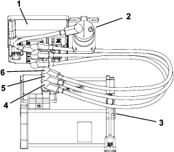
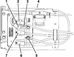
Note: Label all the traction motor electrical leads for assembly purposes (Figure 4).
-
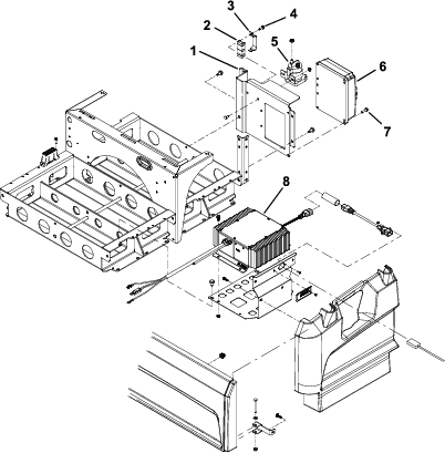
Disconnect the electrical conductors from the controller and position them away from controller as follows:
-
Support the controller to prevent it from falling.
-
Remove the 4 washer-head screws securing the controller to the controller bracket (Figure 6).
-
Carefully remove the controller from the machine.
-
If necessary, remove the washer-head screw securing the isolator retainer, isolator, and controller cables to the controller bracket (Figure 6).
-
Separate the isolator and controller cables from the bracket (Figure 6).
Installing the New Controller
Parts needed for this procedure:
| Controller | 1 |
-
If you removed the isolator and controller cables from the controller bracket, insert the cables into the isolator (Figure 6).
-
Secure the isolator and cables to the bracket using the isolator bracket and washer-head screw (Figure 6).
-
Torque washer-head screw to 10.2 to 12.4 N∙m (90 to 110 in-lb).
-
Secure the controller to the controller bracket using 4 washer-head screws (Figure 6).
-
Ensure that the controller terminals and cables are clean (no corrosion) and in good condition.
-
Connect the electrical conductors to the controller as follows:
-
Carefully plug the wire-harness connector into the controller.
Ensure that the connector is fully plugged into the controller socket.
-
Secure the controller cables to controller terminals B+, B−, M1, M2, and M3 using the cap screw, lock washer, and flat washer (Figure 5).
-
Torque the cap screws to 10 to 12 N∙m (89 to 106 in-lb).
-
-
Connect the conductors between the battery pack and machine components.
-
Torque the hex nuts on the battery terminals to 10.8 to 11.8 N∙m (95 to 105 in-lb).
-
After you make all the cable connections, apply Toro battery terminal protector to all the battery posts and the controller-cable connectors to prevent corrosion.
Ensure that the cable terminal boots are positioned over all the connections.
-
Lower and secure the cargo bed.
-
Before returning the machine to operation, fully charge the batteries by connecting the on-board battery charger to an appropriate electrical outlet.