Introduction

Important: These installation instructions contain engine operation and maintenance information that supersedes the engine information in your machine Operator’s Manual.Before operating or maintaining the machine or engine, always refer to the safety in your Operator’s Manual.Save these instructions.

Important: This engine's warranty is provided by the engine manufacturer. Please refer to the engine manufacturer's warranty and emissions system warranty included in the literature packet. That warranty applies only to the engine. It does not expand or otherwise alter any express or implied warranty terms or warranty period that may apply to the product into which the engine is installed.

Warning

CALIFORNIA

Proposition 65 Warning

The engine exhaust from this product contains chemicals known to the State of California to cause cancer, birth defects, or other reproductive harm.

Safety

Safety and Instructional Decals

Graphic

Safety decals and instructions are easily visible to the operator and are located near any area of potential danger. Replace any decal that is damaged or missing.

decal115-1614
decal120-2769
decal125-5245
decal130-8322
decal133-8062

Installation

For models 04034, 04035, 04036, 04037, 04052 (TE), and 04060 (TE) made in 2008 or newer.

Note: If the machine is equipped with an incandescent light kit, you may need to order a new kit; contact your local Toro dealer for more information.

Removing the Old Engine

Important: Save all fasteners that you removed for reuse unless otherwise noted.

  1. Prepare the machine; refer to Preparing the Machine for Maintenance.

  2. Remove the old bellcrank cover and keep the 1/4 turn stud, 2 washers, mounting bracket, and the mounting bracket screws and washers.

    Note: Discard the bellcrank cover.

  3. Remove the V-belts from the driver pulley.

  4. Remove and discard the wiring harness.

  5. Remove the brake and traction lever grips, and console cover.

  6. Remove and discard the throttle control cable.

  7. Disconnect the traction cable from the clutch assembly on the engine.

  8. Disconnect the brake cable from the brake lever.

  9. Remove and discard the throttle lever, but retain the spring and mounting hardware.

  10. Remove the traction lever and traction cable from the old traction bracket.

  11. Remove the handle assembly.

  12. Remove and discard the old traction bracket, but retain the proximity switch and mounting hardware.

  13. Remove the old engine and mounting bolts and nuts.

  14. Remove and discard the old engine mounting bracket, but retain the engine and engine mounting bracket bolts.

  15. Clean the frame and check for damage or wear.

Installing the New Engine

Parts needed for this procedure:

Engine1
Engine conversion mounting bracket1
Wire harness plate1
Interlock module1
Wiring harness1
Throttle lever1
Traction bracket1
Throttle cable1
Key1
Washer1
Short bolt4
Drive pulley input1
Clutch bracket1
Clutch lever1
Lock washer1
Long bolt1
Flange-head bolt1
Engine switch1
Clip2
Bellcrank cover1
Cable tie4
Idler pulley assembly1
Belt guide1
Locknut2
Flat washer1
Cotter pin1

Note: If the machine does not have an engine switch on the console, add a space for one using the dimensions in Figure 1.

g021517

Note: Refer to Figure 6 for installing the new engine.

  1. Attach the clutch bracket to the engine with the 4 short bolts from the kit.

  2. Install the key onto the engine drive shaft.

    Note: Apply anti-seize compound to the key and engine drive shaft before installing.

  3. Install the new drive pulley input with a new lock washer, a washer, and a long bolt.

  4. Install the new clutch lever to the new clutch bracket using the torque spring, washer, and bolt from the old clutch lever and bracket (Figure 2).

    g025179
  5. Install the old cable link to the clutch lever and secure it using the washer and cotter pin.

  6. Install the new idler pulley assembly, belt guide, and locknut to the clutch lever.

  7. Remove the traction lever assembly and necessary parts from the old clutch bracket and install them on the new clutch bracket (Figure 3).

    g025180
  8. Attach the wiring harness bracket to the fuel tank using the 2 rear flange nuts securing the tank to the engine (Figure 6).

  9. Install the interlock module to the wiring harness bracket with the new flange-head bolt.

  10. Install the engine conversion mounting bracket to the machine with the previously removed bolts.

    Note: To make installing the engine to the frame easier, tighten the bolts 90% of the way.

  11. Mount the engine onto the engine conversion mounting bracket using 3 of the existing bolts and nuts, leaving the front right mounting hole open.

    Note: To make installing the engine to the frame easier, tighten the bolts 90% of the way.

  12. Install the new traction bracket to the handle using the previously removed hardware.

    Note: If the original traction bracket was attached to the machine through 2 holes in the handle, order Part Nos. 112-9318 and 110-2415 to complete the installation.

  13. Install the previously removed handle assembly.

  14. Install the previously removed traction lever and cable.

  15. Install and adjust the interlock switch according to the instructions in your Operator’s Manual.

  16. Install the new throttle lever and cable using the previously removed hardware.

    Note: Ensure that you are using the correct cable for your model.

    Note: Tighten the nut on the throttle spring until the spring is fully compressed, then back off 1/2 turn. At high idle the throttle lever should not move; if it moves, tighten the nut on the throttle spring slightly.

  17. Connect the brake cable to the brake lever.

  18. Install the previously removed console cover and handle grips.

    Note: Trim the slot in the console cover if the throttle lever makes contact with the plastic at full throttle.

  19. Install the traction cable to the clutch bracket.

  20. Using the old throttle cable clip, attach the new throttle cable to the rear of the differential housing (Figure 4).

    g021514
  21. Attach the new clip to the throttle cable and bolt it to the engine conversion mounting bracket with the remaining bolt (Figure 5).

    g021515
  22. Connect the traction cable to the engine and adjust it according to the instructions in your Operator’s Manual.

    Note: If the traction cable cannot be adjusted properly, replace the cable.

  23. Install and adjust the V-belts; refer to your Operator’s Manual.

  24. Tighten all of the engine mounting bracket and engine conversion mounting bracket bolts.

  25. Connect the wiring harness to the interlock module, and route the harness up the left side of the handle.

  26. Install the engine switch in the console and connect it to the wiring harness.

    Note: Connect the wiring harness to the hour meter if the machine is equipped with one.

  27. Snap the wiring harness into place under the console cover.

    Note: You may need to drill holes for the wiring harness clips to snap through.

  28. Mount the green ground wire using the cowling bolt under the fuel tank, and connect the red wire to the engine.

    Note: Apply skin-over grease to the bolt and ground lug terminal.

  29. Clip the wiring harness to the mounting bracket.

  30. Install the 1/4 turn stud and 2 washers to the bellcrank cover, and install the cover assembly, mounting bracket, and mounting bracket screws and washers.

  31. Attach the cables and wiring harness to the handles using the 4 new cable-ties.

  32. Lubricate the machine according to the instructions in your Operator’s Manual.

  33. Fill the engine crankcase with oil according to the instructions in your Operator’s Manual.

  34. Adjust the engine speed to the following specifications:

    High idle (no load)3375 ±100 rpm
    Low idle (no load)1565 ±150 rpm
    g025181

Product Overview

g264589

Choke Control

The choke control is located at the left side of the control console; you use it to help start a cold engine (Figure 7).

Note: Do not start or run a warm engine with the choke in the ON position.

  • Pull up on the choke control to set the choke to the ON position.

  • Push down on the choke control to set the choke to the OFF position.

Fuel-Shut-Off Valve

The fuel-shut-off valve is located at the front, right side of the engine below the fuel tank (Figure 7).

Note: Close the fuel-shut-off valve when the machine is not used for a few days, during transport to and from the job site, or when the machine is parked inside a building; refer to Opening and Closing the Fuel-Shut-Off Valve.

Operation

Fuel Specification

Petroleum fuelUse unleaded gasoline with an octane rating of 87 or higher ((R+M)/2 rating method).
Ethanol blended fuelUse an unleaded-gasoline blend with up to 10% ethanol (gasohol) or 15% MTBE (methyl tertiary butyl ether) by volume is acceptable. Ethanol and MTBE are not the same.
Gasoline with 15% ethanol (E15) by volume is not approved for use. Never use gasoline that contains more than 10% ethanol by volume, such as E15 (contains 15% ethanol), E20 (contains 20% ethanol), or E85 (contains up to 85% ethanol). Using unapproved gasoline may cause performance problems and/or engine damage which may not be covered under warranty.

Important: For best results, use only clean, fresh fuel (less than 30 days old).

  • Do not use gasoline containing methanol.

  • Do not store fuel either in the fuel tank or fuel containers over the winter unless you use a fuel stabilizer.

  • Do not add oil to gasoline.

Using Stabilizer/Conditioner

Use a fuel stabilizer/conditioner in the machine to provide the following benefits:

Important: Do not use fuel additives containing methanol or ethanol.

Add the correct amount of fuel stabilizer/conditioner to the gasoline.

Note: A fuel stabilizer/conditioner is most effective when mixed with fresh gasoline. To minimize the chance of varnish deposits in the fuel system, use fuel stabilizer at all times.

Filling the Fuel Tank

Fuel tank capacity: 2.7 L (0.71 US gallons)

  1. Park the machine on a level surface and shut off the engine.

  2. Allow the engine to cool.

  3. Clean around the fuel-tank cap and remove it (Figure 8).

    g264553
  4. Fill the tank with fuel (Figure 8) to within 6 to 13 mm (1/4 to 1/2 inch) from the top of the tank. Do not fill into the filler neck of the tank.

    Important: Do not fill the tank more than 6 mm (1/4 inch) from the top of the tank because the fuel needs room to expand.

  5. Install the fuel-tank cap securely.

  6. Wipe up any spilled fuel.

Opening and Closing the Fuel-Shut-Off Valve

Control fuel flow to the engine with the fuel-shut-off valve as follows:

  • Rotate the handle for the fuel-shut-off valve 90 degrees clockwise to the open the valve.

  • Rotate fuel-shut-off valve handle 90 degrees counterclockwise to close the valve.

g027146

Maintenance

Important: Refer to your engine owner’s manual for additional maintenance procedures.

Recommended Maintenance Schedule(s)

Maintenance Service IntervalMaintenance Procedure
After the first 20 hours
  • Change the engine oil.
  • Before each use or daily
  • Check the engine-oil level.
  • Every 50 hours
  • Clean the foam air-cleaner element (More often under severe conditions).
  • Every 100 hours
  • Change the engine oil
  • Check and gap the spark plug.
  • Every 200 hours
  • Replace the dual element air filter.
  • Preparing the Machine for Maintenance

    Warning

    While you are maintaining or adjusting the machine, someone could start the engine. Accidentally starting the engine could seriously injure you or other bystanders.

    Remove the key from the ignition, engage parking brake, and pull the wire(s) off the spark plug(s) before you do any maintenance. Also push the wire(s) aside so it does not accidentally contact the spark plug(s).

    Perform the following before servicing, cleaning, or making any adjustments to the machine.

    1. Park the machine on a level surface.

    2. Shut off the engine and remove the key from the machine (if equipped).

    3. Engage the parking brake.

    4. Wait for all moving parts to stop allow the engine to cool before servicing, storing, or making repairs.

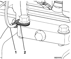
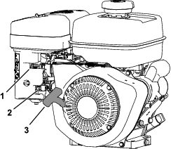
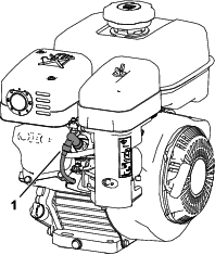
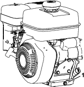
    5. Disconnect the spark-plug wire (Figure 10).

      g259487

    Servicing the Air Cleaner

    Maintenance Service IntervalMaintenance Procedure
    Every 200 hours
  • Replace the dual element air filter.
  • Important: Do not apply oil to the foam or paper element.

    Removing the Foam and Paper Elements

    1. Prepare the machine for maintenance; refer to Preparing the Machine for Maintenance.

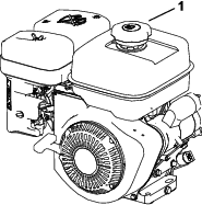
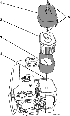
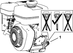
    2. Clean around the air cleaner to prevent dirt from getting into the engine and causing damage (Figure 11).

      g033510
    3. Rotate the wing nut that secures the air-cleaner cover counterclockwise and remove the air-cleaner cover (Figure 11).

    4. Rotate the wing nut that secures the paper and foam-filter elements counterclockwise and remove the filter elements from the hold-down rod (Figure 11).

    5. Carefully pull the foam element off the paper element (Figure 11).

      Note: Inspect the paper and foam-filter elements for damage or an excessive accumulation of dirt. Replace the damaged filters. Clean the foam-filter element if it is dirty. Replace the paper-filter element if it is dirty.

    Servicing the Foam Filter Element

    Maintenance Service IntervalMaintenance Procedure
    Every 50 hours
  • Clean the foam air-cleaner element (More often under severe conditions).
    1. Inspect the element for tears, an oily film, or damaged (Figure 11).

      Important: Replace the foam element if it is worn or damaged.

    2. Wash the foam element in liquid soap and warm water. When the element is clean, rinse it thoroughly.

    3. Dry the element by squeezing it in a clean cloth.

    4. Air dry the foam-filter element.

    Installing the Foam and Paper-Filter Elements

    Important: To prevent engine damage, always operate the engine with the complete foam and paper air-cleaner assembly installed.

    1. Carefully slide the foam-filter element onto the paper-filter element (Figure 11).

    2. Align the hole in the top plate of the paper-filter element with the hold-down rod of the carburetor (Figure 11).

    3. Secure the filter elements to the carburetor with the wing nut (Figure 11) that you removed in step 4 of Removing the Foam and Paper Elements.

    4. Align the hole in the air-cleaner cover with the hold-down rod (Figure 11) and secure the cover to the rod with the wing nut that you removed in step 3 of Removing the Foam and Paper Elements.

    Engine Oil Specification

    Oil Type: Detergent oil (API service SJ or higher)

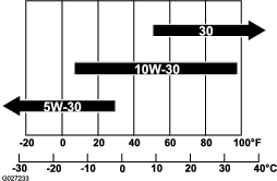
    Oil viscosity: Refer to the table below.

    g027233

    Checking the Engine-Oil Level

    Maintenance Service IntervalMaintenance Procedure
    Before each use or daily
  • Check the engine-oil level.
  • Important: Do not operate the engine with the oil level below the Low (or Add) mark on the dipstick, or over the Full mark.

    1. Move the machine to a level surface.

    2. Prepare the machine for maintenance; refer to Preparing the Machine for Maintenance.

    3. Allow the engine to cool.

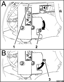
    4. Remove the dipstick from the engine and wipe the dipstick with a clean rag (Figure 13).

      g027234
    5. Insert the dipstick from the engine as shown in Figure 13.

      Note: Do not thread the dipstick into the filler neck when checking the engine oil level.

    6. Remove the dipstick from the filler neck and look at the oil level in the dipstick (Figure 13).

      Note: The engine oil level must cover between the hatch marked areas on the dipstick (Figure 13).

    7. If the oil level is low, wipe off the area around the filler neck and add the specified oil until the oil level is between the hatch marked areas on the dipstick.

      Important: Do not overfill the engine with oil.

    8. Hand tighten the dipstick into the filler neck (Figure 13).

    Changing the Engine Oil

    Maintenance Service IntervalMaintenance Procedure
    After the first 20 hours
  • Change the engine oil.
  • Every 100 hours
  • Change the engine oil
  • Draining the Engine Oil

    Important: Do not operate the engine with the oil level below the Low (or Add) mark on the dipstick, or over the Full mark.

    1. Start and run the engine for a few minutes to warm the engine oil.

    2. Prepare the machine for maintenance; refer to Preparing the Machine for Maintenance.

    3. At the rear of the machine, place a drain pan under the drain plug.

      g264566
    4. Remove the drain plug from the engine and allow the oil to drain completely.

    5. Push down on the handle to tip the machine and engine backward, allowing all the oil to run into the drain pan.

      Important: Do not tip the machine at an angle greater than 25°. Tipping the machine beyond 25° leads to oil leaking into the combustion chamber and/or fuel leaking out of the fuel-tank cap.

    6. Install the drain plug and refill the crankcase with the specified oil; refer to Adding Oil to the Engine.

    7. Torque the drain plug to 20 to 23 N∙m (15 to 17 ft-lbs).

    8. Wipe up any spilled oil and dispose of the used oil properly.

    Adding Oil to the Engine

    Engine Oil Capacity: 0.6 L (20 fl oz)

    Important: Do not operate the engine with the oil level below the Low (or Add) mark on the dipstick, or over the Full mark.

    1. Remove the dipstick from the filler neck of the engine and wipe clean the dipstick with a rag (Figure 15).

      g264565
    2. Slowly pour 0.6 L (20 fl oz) of the specified oil into the crank case of the engine through the filler neck (Figure 15).

    3. Insert the dipstick from the engine as shown in Figure 16.

      Note: Do not thread the dipstick into the filler neck when checking the engine oil level.

      g027234
    4. Remove the dipstick from the filler neck and look at the oil level in the dipstick (Figure 15).

      Note: The engine oil level must cover between the hatch marked areas on the dipstick (Figure 15).

    5. If the oil level is low, add the specified oil into the engine until the oil level is between the hatch marked areas on the dipstick.

      Note: Do not overfill the engine with oil.

    6. Hand tighten the dipstick into the filler neck (Figure 15).

    Servicing the Spark Plug

    Maintenance Service IntervalMaintenance Procedure
    Every 100 hours
  • Check and gap the spark plug.
  • Spark Plug Specification

    Spark Plug Type: NGK BR6HS, Champion RTL86C, or equivalent

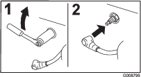
    Removing the Spark Plug

    1. Prepare the machine for maintenance; refer to Preparing the Machine for Maintenance.

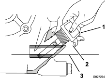
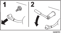
    2. Remove the spark plug as shown in Figure 17.

      g008791

    Checking the Spark Plug

    Air Gap: 0.6 to 0.7 mm (0.02 to 0.03 inch)

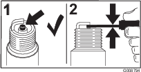
    Important: Do not clean the spark plug(s). Always replace the spark plug(s) when it has a black coating, worn electrodes, an oily film, or cracks.

    If you see light brown or gray on the insulator, the engine is operating properly. A black coating on the insulator usually means the air cleaner is dirty.

    Use a gapping tool/feeler gauge to check and adjust the air gap to 0.6 to 0.7 mm (0.02 to 0.03 inch).

    g008794

    Installing the Spark Plug

    Tighten the spark plug as follows:

    • New spark plug—12 to 15 N∙m (8.7 to 10.8 ft-lb)

    • In-service spark plug—23 to 27 N∙m (16.6 to 19.5 ft-lb)

    g008795