
 , which means Caution, Warning,
or Danger—personal safety instruction. Failure to comply with
these instructions may result in personal injury or death.
, which means Caution, Warning,
or Danger—personal safety instruction. Failure to comply with
these instructions may result in personal injury or death.


Maintenance
Determine the left and right sides of the machine from the normal operating position.
Caution
If you leave the key in the switch, someone could accidently start the engine and seriously injure you or other bystanders.
Remove the key from the switch before you perform any maintenance.
Recommended Maintenance Schedule(s)
| Maintenance Service Interval | Maintenance Procedure |
|---|---|
| Before each use or daily |
|
| Every 25 hours |
|
| Every 50 hours |
|
Greasing the Trencher
| Maintenance Service Interval | Maintenance Procedure |
|---|---|
| Before each use or daily |
|
Grease Type: General-purpose grease
-
Park the machine on a level surface, disengage the auxiliary hydraulics, engage the parking brake, and lower the loader arms.
-
Shut off the engine and remove the key.
-
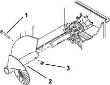
Remove the plug from the idler shaft.
-
Clean the grease fitting with a rag (Figure 9).

-
Connect a grease gun to the fitting.
-
Pump grease into the fittings until grease begins to ooze out of the bearings (approximately 3 pumps).
-
Wipe up any excess grease.
-
Install the plug.
Checking the Hydraulic Lines
| Maintenance Service Interval | Maintenance Procedure |
|---|---|
| Before each use or daily |
|
Warning
Hydraulic fluid escaping under pressure can penetrate skin and cause injury. Fluid injected into the skin must be surgically removed within a few hours by a doctor familiar with this form of injury; otherwise, gangrene may result.
-
Keep your body and hands away from pinhole leaks or nozzles that eject high-pressure hydraulic fluid.
-
Use cardboard or paper to find hydraulic leaks; never use your hands.
Servicing the Planetary Oil
Oil Specifications
Oil type: SAE 80W-90, API service GL-5
Capacity: 0.70 L (24 fl oz)
Checking the Planetary Oil Level
| Maintenance Service Interval | Maintenance Procedure |
|---|---|
| Before each use or daily |
|
-
Park the machine on a level surface, disengage the auxiliary hydraulics, engage the parking brake, and lower the loader arms.
-
Shut off the engine and remove the key.
-
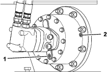
Remove the upper drain plug, at the 3 o’clock position on the planetary, near the quick-attach plate (Figure 10).
-
If oil comes out of the hole, the oil level is correct. If no oil comes out, add oil until it comes out of the hole.
Important: Do not overfill.
-
Install the plug.
Replacing the Planetary Oil
| Maintenance Service Interval | Maintenance Procedure |
|---|---|
| Every 50 hours |
|
-
Park the machine on a level surface, disengage the auxiliary hydraulics, engage the parking brake, and lower the loader arms.
-
Shut off the engine and remove the key.
-
Remove the lower drain plug, at the 6 o’clock position on the planetary, and drain the oil (Figure 10).
-
Install the drain plug.
-
Remove the upper drain plug and add oil until it comes out of the hole.
-
Install the drain plug.
-
Dispose of the used oil at a recycling center.
Flipping a Worn Boom
| Maintenance Service Interval | Maintenance Procedure |
|---|---|
| Every 25 hours |
|
Inspect the bottom of the boom for wear. If it is worn, complete the following:
Note: A boom is worn when grooves from the chain are deep enough that the link rollers contact the boom.
Note: If you have already flipped the boom once, replace the boom when both sides are worn.
-
Park the machine on a level surface, disengage the auxiliary hydraulics, engage the parking brake, and lower the loader arms.
-
Shut off the engine and remove the key.
-
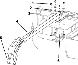
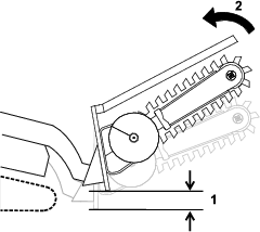
Loosen the jam nuts and move them to as close to the head of the tensioning bolts as possible (Figure 11).
-
Remove the chain from the drive sprocket and boom.
Note: Use a hoist to lift the chain.
-
Remove the boom, flip it over so the bottom becomes the top (or if you have already flipped it once, replace it), and install the boom again (Figure 11).
-
Install the chain over the drive sprocket and idler wheel.
Note: Use a hoist to lift the chain.
-
Adjust the tensioning bolts until there is approximately 2.5 cm (1 inch) of slack between the bottom of the boom and the chain. Tighten the jam nuts.
Note: Ensure to adjust the jam nuts on both bolts evenly.
Replacing the Digging Teeth
| Maintenance Service Interval | Maintenance Procedure |
|---|---|
| Before each use or daily |
|
Due to the high amount of wear placed on the digging teeth, you need to replace them periodically.
To replace a single tooth, remove the bolts and nuts securing the tooth to remove it, then install a new tooth in the same position. Torque the bolts securing the teeth to 37 to 45 N∙m (27 to 33 ft-lb).
Replacing the Digging Chain
Removing the Digging Chain
Preparing to Remove the Digging Chain
-
Park the machine on a level surface, lower the loader arms, and tilt the boom to the horizontal position.
-
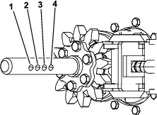
Rotate the digging chain until the master pin is positioned at the top of the idler wheel (Figure 15).
-
Shut off the engine and remove the key.
-
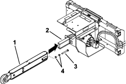
Remove the bolt and locknut securing the spoils auger and remove the auger (Figure 13).
Note: Retain the hardware for installation later.
-
Loosen the jam nuts and move them to as close to the head of the tensioning bolts as possible (see Figure 11).
Removing the Master Pin in the Digging Chain
-
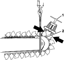
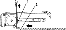
Counting from the master pin, loop a 3.65 m (12 foot) lifting strap with a lifting capacity of 181.4 kg (400 lb) around the chain at the digging tooth of the fifth or sixth link below and forward of the boom (Figure 14).
-
With the strap attached to the lifting equipment, raise the lifting strap enough to support the digging chain.
-
Clamp the ends of the chain with a with a chain clamp at the link rollers at either side of the inner and outer plates at the master pin (Figure 14).
-
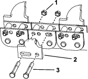
Straighten or cut off the tail of the safety pin and remove the pin (Figure 15).
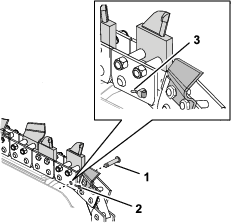
Note: Discard the safety pin.
-
Remove the master pin and the roller for the master pin (Figure 15).
Note: Retain the master pin and the roller for installing the replacement chain.
Removing the Digging Chain from the Machine
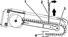
-
Lower the lifting equipment until the end of the digging chain is laying on the ground (Figure 16).
-
Remove the lifting strap.
-
Start the machine and lower the boom until the idler wheel is positioned 31 to 36 cm (12 to 14 inches) above the ground (Figure 16).
-
Start the machine and slowly engage the forward-flow auxiliary hydraulics.
-
When the digging chain has cleared the drive sprocket, shut off the auxiliary hydraulics, shut off the machine, and remove the key.
-
Wrap the lifting strap around the digging chain at the idler wheel, and attach the strap to the lifting equipment (Figure 16).
-
Raise the lifting equipment and remove the digging chain from the boom (Figure 16).
Installing the Digging Chain
Preparing to Install the Digging Chain
-
Park the machine on a level surface, lower the loader arms, and tilt the boom to the horizontal position.
-
Shut off the engine and remove the key.
-
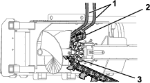
Lay the digging chain on the ground in a straight line, below the lifting equipment such as a hoist, and with the cutting face of the teeth pointing toward the path where you will move the machine (forward) to position it over the digging chain (Figure 17).
-
At the forward end of the chain, loop a 3.65 m (12 foot) lifting strap with a lifting capacity of 181.4 kg (400 lb) around the chain at the digging tooth of the third or fourth link of the chain (Figure 17).
-
Start the machine and position the trencher boomover the digging chain and with the lifting strap forward of the drive sprocket of the trencher (Figure 17).
Note: When positioned correctly, the boom of the trencher is aligned with the digging chain.
-
Turn the machine off and remove the key.
Aligning the Digging Chain
This procedure requires 2 people to align the digging chain to the machine.
-
Route the ends of the lifting strap forward of the sprocket hub, on either side of the drive sprocket.
-
Connect the ends of the lifting strap to the lifting equipment, and raise the end of the chain until the drive pins engage the drive sprocket (Figure 18).
-
Start the machine and slowly engage the forward-flow auxiliary hydraulics to drive the chain onto the upper wear strip of the boom.
Important: If the chain is not aligned or engaged with the drive sprocket, shut off the machine, remove the key, and align the chain to the drive sprocket.
Note: Maintain tension on the strap until the end of the chain is on the upper wear strip.
-
Lower the lifting strap as the chain moves around the sprocket and into position on the upper wear strip.
-
Shut off the auxiliary hydraulics when the end of the chain is positioned on top of the idler wheel (Figure 19).
-
Shut off the machine and remove the key.
-
Remove the lifting strap from the machine.
Linking the Digging Chain
-
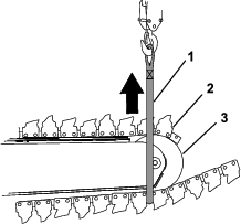
At the end of the chain laying on the ground, loop the lifting strap around the chain at the digging tooth of the fifth or sixth link of the chain (Figure 19).
-
Raise the chain and position it around the idler wheel (Figure 19 and Figure 14).
Note: Rotate the auger as necessary to engage the teeth of auger drive sprocket with the digging chain.
-
Clamp the ends of the chain with a with a chain clamp at the link rollers at either side of the inner and outer plates at the master pin (Figure 14).
-
Align the hole of a link roller with the holes in the inner plates at the end of the chain (Figure 15).
-
Align the holes in the inner plates and the roller of the chain with the holes in the outer plates of the other end of the chain (Figure 15).
-
Align the master pin with the hole in the pin parallel with the chain plates forward of the idler wheel (Figure 15).
-
Insert the master pin through the digging chain plates.
-
Insert the safety pin through the master pin with the head of the pin toward the idler wheel (Figure 15).
Important: Do not install a used safety pin. Only use a new safety pin.
-
Remove the lifting strap and the chain clamp.
-
Bend the tail of the safety pin down 30° to 45° (Figure 15).
-
Install the spoils auger; refer to Installing the Spoils Auger.
-
Adjust the tension of the digging chain; refer to Adjusting the Chain Tension.
Adjusting the Chain Tension
| Maintenance Service Interval | Maintenance Procedure |
|---|---|
| Before each use or daily |
|
With the trencher parallel to the ground, ensure that there is approximately 2.5 cm (1 inch) between the bottom of the boom and the top of the bottom chain span. If not, adjust the chain using the following procedure:
-
Park the machine on a level surface, disengage the auxiliary hydraulics, engage the parking brake, and lower the loader arms.
-
Shut off the engine and remove the key.
-
Rotate the jam nut closest to the tube to adjust the tensioning bolt until there is approximately 2.5 cm (1 inch) of slack between the bottom of the boom and the chain (Figure 3). Tighten the other jam nut against the first jam nut.
Note: Ensure to adjust the jam nuts on both bolts evenly.
-
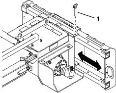
Loosen the 4 nuts securing the crumber to the trencher and slide it outward so that there is at least 5 cm (2 inches) between the chain and the crumber plate (Figure 5).
-
Tighten the 4 nuts.
Replacing the Drive Sprocket
Over time, the drive sprocket will wear, especially when used in sandy or clay soils. When this happens, the digging chain will begin to slip. If the chain slips, replace the drive sprocket as follows:
-
Park the machine on a level surface, disengage the auxiliary hydraulics, engage the parking brake, and lower the loader arms.
-
Raise the trencher a few centimeters (inches) above the ground.
-
Shut off the engine and remove the key.
-
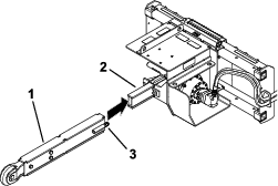
Remove the spoils auger (Figure 20).
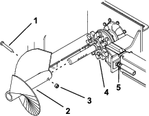
-
Loosen the jam nuts and move them to as close to the head of the tensioning bolts as possible (Figure 20).
-
Remove the chain from the drive sprocket and boom.
-
Remove the 6 bolts (5/8 x 2-1/2 inches) and nuts (5/8 inch) securing the drive sprocket (Figure 20).
-
Remove and discard the drive sprocket (Figure 20).
-
Clean the sprocket mounting surface on the trencher.
-
Apply thread-locking compound to the 6 bolts (5/8 x 2-1/2 inches), and install the sprocket halves, bolts, and nuts (5/8 inch) finger tight (Figure 20).
-
Slowly begin tightening the bolts progressing around the sprocket until all bolts are torqued to 129 to 155 N∙m (95 to 115 ft-lb).
Important: Tighten each bolt only half way first, working your way around the 6 bolts, then return to each bolt in turn and torque them.
-
Install the digging chain; refer to Installing the Digging Chain.
-
Install the spoils auger; refer to Installing the Spoils Auger.