
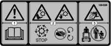
 , which means Caution, Warning,
or Danger—personal safety instruction. Failure to comply with
these instructions may result in personal injury or death.
, which means Caution, Warning,
or Danger—personal safety instruction. Failure to comply with
these instructions may result in personal injury or death.


Maintenance
Determine the left and right sides of the machine from the normal operating position.
Caution
If you leave the key in the switch, someone could accidently start the engine and seriously injure you or other bystanders.
Remove the key from the switch before you perform any maintenance.
Recommended Maintenance Schedule(s)
| Maintenance Service Interval | Maintenance Procedure |
|---|---|
| Before each use or daily |
|
| Before storage |
|
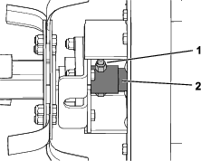
Greasing the Tiller
| Maintenance Service Interval | Maintenance Procedure |
|---|---|
| Before each use or daily |
|
| Before storage |
|
Grease immediately after every washing.
Grease Type: General-purpose grease
-
Park the machine on a level surface and disengage the auxiliary hydraulics.
-
Shut off the engine, remove the key, and wait for all moving parts to stop before leaving the operating position.
-
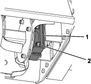
Grease the rotor bearing shown in Figure 5.
-
Wipe up any excess grease.
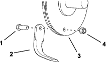
Replacing the Tiller Tines
| Maintenance Service Interval | Maintenance Procedure |
|---|---|
| Before each use or daily |
|
Note: Worn or dull tines degrade the performance of the tiller.
-
Park the machine on a level surface and disengage the auxiliary hydraulics.
-
Shut off the engine, remove the key, and wait for all moving parts to stop before leaving the operating position.
-
Note the direction that the tiller tine is oriented.
-
Remove the bolt (5/8 x 1-3/4 inch), nut (5/8 inch), and tine (Figure 6).
-
Clean dirt and debris from the tine pocket.
-
Install the new tine, orienting it the same direction as the old tine (Figure 6).
-
Torque the bolt to 183 to 223 N∙m (135 to 165 ft-lb).
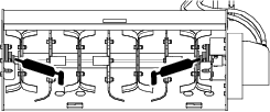
Replacing the Rotor Assembly
Removing the Rotor Assembly
-
Remove the tiller from the traction unit.
-
Use a hoist to lay the tiller back on the attachment plate.
-
Remove the nut (5/8 inch) and bolt (5/8 x 4 inches) securing the drive adapter to the rotor assembly (Figure 7).
-
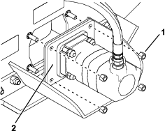
Remove the 4 nuts (9/16 inch) securing the motor mount (Figure 8). Remove the mount with the motor.
-
Support the rotor assembly using a hoist and remove the 4 locknuts (5/8 inch), 4 washers, and 4 bolts (5/8 x 2-1/2 inches) securing the bearing guard and bearing on each end of the rotor assembly (Figure 9).
-
Remove the rotor assembly.
Installing the Rotor Assembly
-
Install the rotor assembly with the 2 bearing guards and bearings using 4 locknuts (5/8 inch), 4 washers, and 4 bolts (5/8 x 2-1/2 inches) for both sets of guards and bearings (Figure 9). Torque the bolts to 183 to 224 N∙m (135 to 165 ft-lb).
-
Using 4 nuts (9/16 inch), install the rotor mount and motor (Figure 8). Torque the nuts to 127 to 157 N∙m (94 to 116 ft-lb).
-
Secure the drive adapter to the rotor assembly using a nut (5/8 inch) and bolt (5/8 x 4 inches) as shown in Figure 7. Torque the bolt to 183 to 224 N∙m (135 to 165 ft-lb)
Checking the Hydraulic Lines
| Maintenance Service Interval | Maintenance Procedure |
|---|---|
| Before each use or daily |
|
Warning
Hydraulic fluid escaping under pressure can penetrate skin and cause injury. Fluid injected into the skin must be surgically removed within a few hours by a doctor familiar with this form of injury; otherwise, gangrene may result.
-
Keep your body and hands away from pinhole leaks or nozzles that eject high-pressure hydraulic fluid.
-
Use cardboard or paper to find hydraulic leaks; never use your hands.