Installation
Preparing the Machine
-
Park the machine on a level surface.
-
Engage the parking brake.
-
Shut off the engine.
-
Remove the spark-plug wire from the spark plug; refer to your machine Operator’s Manual.
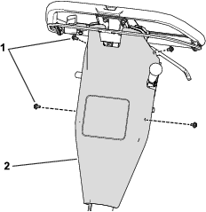
Removing the Control Cover
Installing the Proximity-Sensor Assembly and Interlock Module
Parts needed for this procedure:
| Proximity-sensor assembly | 1 |
| Double-ended screw | 2 |
| Flange nut (1/4 inch) | 2 |
| Interlock module | 1 |
| Hex-head bolt (3/8 inch) | 2 |
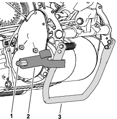
Installing the Proximity-Sensor Assembly
Refer to Figure 3 for this procedure.
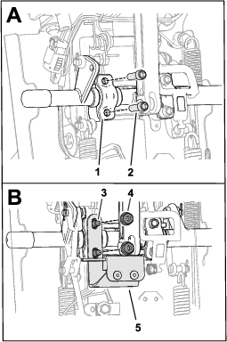
-
Remove the socket-head screws from the spacer on the control shaft
-
Use 2 double-ended screw and 2 flange nuts (1/4 inch) to install the proximity-sensor assembly to the spacer on the control shaft.
-
Torque the screws and nuts to 9 to 12 N∙m (7 to 9 ft-lb).
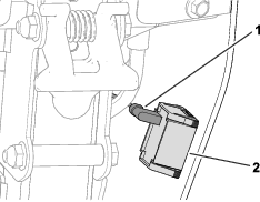
Installing the Interlock Module
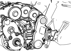
Use 2 hex-head bolts (3/8 inch) to install the interlock module to the cable bulkhead (Figure 4).
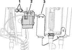
Installing the Wire Harness
Parts needed for this procedure:
| Wire harness | 1 |
Install the wire harness as follows:
-
Wire-harness end with the 6-socket connector: install to the interlock module.
-
Wire-harness end labeled : install to the proximity-sensor connector.
-
Wire-harness end labeled : install to the machine-wire-harness end labeled TO INTERLOCK MODULE.
Installing the Control Cover
Refer to the illustrations in Removing the Control Cover for this procedure.
-
Use the previously-removed screws to install the control cover.
-
Connect the wire-harness connector to the hour meter.
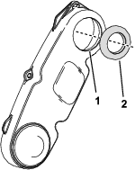
Installing the Backlap Knob to the Reel-Drive Assembly
Parts needed for this procedure:
| Drive hub | 1 |
| Seal | 1 |
-
Remove the plug from the top of the reel-drive assembly (Figure 5).
-
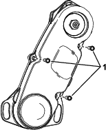
Remove the 3 bolts that secure the cover to the reel-drive assembly and remove the reel-drive cover (Figure 6).
-
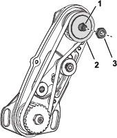
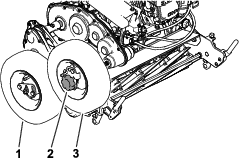
While securing the drive pulley from movement, remove the nut from the reel-drive shaft (Figure 7).
-
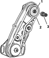
While securing the drive pulley from movement, install the drive hub to the reel-drive shaft (Figure 8).
-
While securing the drive pulley from movement, torque the drive hub to 37 to 44 N⋅m (27 to 32 ft-lb).
-
Lubricate the lip of the reel-drive cover and press the seal flush into the cover (Figure 9).
-
Install the cover to the reel-drive assembly with the bolts that you removed in step 2; refer to Figure 6.
Preparing to Backlap
Parts needed for this procedure:
| Bail catch | 1 |
| Knob | 1 |
| Axle-lock bracket | 1 |
| Transport Wheel Kit (order separately; contact your authorized Toro distributor) | 1 |
-
Install the spark-plug wire to the spark plug; refer to your machine Operator’s Manual.
-
Gather the remaining loose parts (i.e., the bail catch, knob, and axle-lock bracket) and the transport wheels for use in Backlapping the Cutting Unit.
Operation
Backlapping the Cutting Unit
Preparing the Machine for Backlapping
-
Move the kickstand to the TRANSPORT-WHEEL SERVICE position; refer to your machine Operator’s Manual.
-
Note the position of the traction drum (refer to your machine Operator’s Manual) and install the axle-lock bracket to the left axle shaft as follows:
-
Drum set to the LOW position: slide the bracket over the shaft with the shorter prong facing toward the machine.
-
Drum set to the HIGH position: slide the bracket over the shaft with the longer prong facing toward the machine (as shown in Figure 10).
-
-
Install the transport wheels onto the right-wheel shaft and the drive hub; refer to Figure 11.
-
Remove the coupler from the transmission driveshaft and adjust the reel-drive assembly to ensure that the wheels are contacting; refer to the cutting unit maintenance section of your machine Operator’s Manual.
-
Install the knob over the wheel on the drive hub (Figure 11).
Performing a Backlapping Job
Danger
Contact with the reel or other moving parts can result in personal injury.
-
Stay away from the reel while backlapping.
-
Do not use a short-handled paint brush for backlapping. A brush and handle assembly (Part No. 29-9100) is available from your authorized Toro distributor.
-
Start the engine; refer to your machine Operator’s Manual.
-
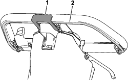
Engage the traction drive as follows:
-
Machines equipped with the clutch bail: Engage the clutch bail and install the bail catch (Figure 12).
-
Machines equipped with the Traction Lever Kit: Move the traction lever down to the ENGAGED position; refer to the kit Installation Instructions.
-
-
Use a long-handled brush to apply lapping compound to the rotating reel.
-
When the backlapping operation is completed and cutting reel is not moving, perform the following steps:
-
Run a file across the front face of the bedknife.
Note: This will remove any burrs or rough edges that may have built up on the cutting edge.
-
Remove the bail catch and axle-lock bracket.
-
Align the reel-drive assembly with the transmission driveshaft and Install the reel-drive coupler to the driveshaft; refer to the cutting unit maintenance section of your machine Operator’s Manual.
-