| Maintenance Service Interval | Maintenance Procedure |
|---|---|
| Before each use or daily |
|
Introduction
This machine is a multi-purpose machine intended to be used by professional, hired operators in commercial applications. It is designed primarily for mowing grass on well-maintained lawns in parks, golf courses, sports fields, and on commercial grounds.
Important: To maximize the safety, performance, and proper operation of this machine, carefully read and fully understand the contents of this Operator’s Manual. Failing to follow these operating instructions or to receive proper training may result in injury. For more information on safe operating practices, including safety tips and training materials, go to www.Toro.com.
You may contact Toro directly at www.Toro.com for product and accessory information, help finding a dealer, or to register your product.
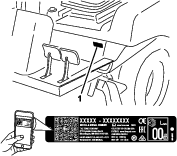
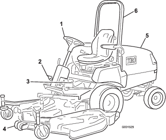
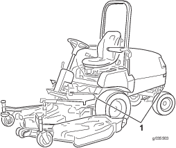
Whenever you need service, genuine Toro parts, or additional information, contact an authorized Toro dealer and have the model and serial numbers of your product ready. Figure 1 identifies the location of the model and serial numbers on the product. Write the numbers in the space provided.
Important: With your mobile device, you can scan the QR code (if equipped) on the serial number plate to access warranty, parts, and other product information.
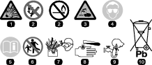
This manual identifies potential hazards and has safety messages identified by the safety-alert symbol (Figure 2), which signals a hazard that may cause serious injury or death if you do not follow the recommended precautions.

This manual uses 2 words to highlight information. Important calls attention to special mechanical information and Note emphasizes general information worthy of special attention.
This product complies with all relevant European directives; for details, please see the separate product specific Declaration of Conformity (DOC) sheet.
It is a violation of California Public Resource Code Section 4442 or 4443 to use or operate the engine on any forest-covered, brush-covered, or grass-covered land unless the engine is equipped with a spark arrester, as defined in Section 4442, maintained in effective working order or the engine is constructed, equipped, and maintained for the prevention of fire.
The enclosed engine owner's manual is supplied for information regarding the US Environmental Protection Agency (EPA) and the California Emission Control Regulation of emission systems, maintenance, and warranty. Replacements may be ordered through the engine manufacturer.
Warning
CALIFORNIA
Proposition 65 Warning
Diesel engine exhaust and some of its constituents are known to the State of California to cause cancer, birth defects, and other reproductive harm.
Battery posts, terminals, and related accessories contain lead and lead compounds, chemicals known to the State of California to cause cancer and reproductive harm. Wash hands after handling.
Safety
Improper use or maintenance by the operator or owner can result in injury. To reduce the potential for injury, comply with these safety instructions and always pay attention to the safety-alert symbol, which means Caution, Warning, or Danger—personal safety instruction. Failure to comply with the instruction may result in personal injury or death.
This machine has been designed in accordance with EN ISO 5395:2013 when equipped with the proper CE kit (refer to the Declaration of Conformity) and rear weight; refer to step Installing the Rear Weights.
Note: For CE required regulatory data, refer to the Declaration of Conformity supplied with the machine.
This machine has been designed in accordance with ANSI B71.4-2017, when equipped with the proper rear weight; refer to step Installing the Rear Weights.
General Safety
This product is capable of amputating hands and feet and of throwing objects. Always follow all safety instructions to avoid serious personal injury.
Using this product for purposes other than its intended use could prove dangerous to you and bystanders.
-
Read and understand the contents of this Operator’s Manual before starting the engine.
-
Use your full attention while operating the machine. Do not engage in any activity that causes distractions; otherwise, injury or property damage may occur.
-
Do not put your hands or feet near moving components of the machine.
-
Do not operate the machine without all guards and other safety protective devices in place and working on the machine.
-
Keep clear of any discharge opening. Keep bystanders and pets a safe distance away from the machine.
-
Keep children out of the operating area. Never allow children to operate the machine.
-
Stop the machine, shut off the engine, remove the key, and wait for all moving parts to stop before servicing, fueling, or unclogging the machine.
Improperly using or maintaining this machine can result in injury.
To reduce the potential for injury, comply with these safety instructions
and always pay attention to the safety-alert symbol  , which means Caution, Warning,
or Danger—personal safety instruction. Failure to comply with
these instructions may result in personal injury or death.
, which means Caution, Warning,
or Danger—personal safety instruction. Failure to comply with
these instructions may result in personal injury or death.
You can find additional safety information where needed throughout this manual.
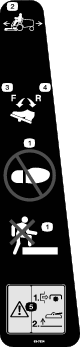
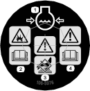
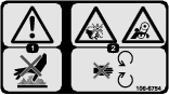
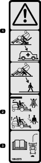
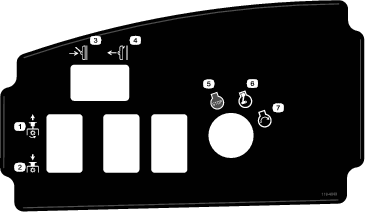
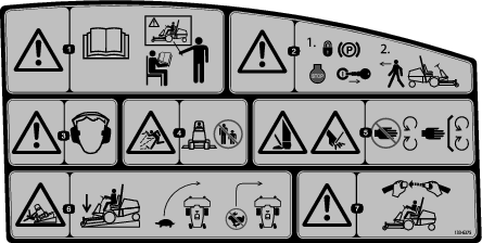
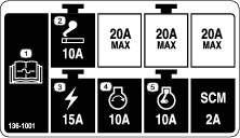
Safety and Instructional Decals
 |
Safety decals and instructions are easily visible to the operator and are located near any area of potential danger. Replace any decal that is damaged or missing. |


Model 30345 only


Setup
Warning
The machine is shipped with the power takeoff (PTO) universal shaft attached to the frame. Do not operate the PTO without first removing the universal shaft or coupling it to a suitable implement.
Note: Determine the left and right sides of the machine from the normal operating position.
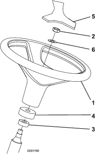
Installing the Steering Wheel
Parts needed for this procedure:
| Steering wheel | 1 |
| Cover | 1 |
-
Remove the steering wheel from the shipping skid (Figure 3).
-
Remove the jam nut and washer from the steering shaft.
Note: Ensure that the foam collar and dust cover remain on the steering shaft (Figure 3).
-
Slide the steering wheel and washer onto the steering shaft (Figure 3).
-
Secure the steering wheel to the shaft with the jam nut. Tighten the jam nut to 27-35 N∙m (20-26 ft-lb).
-
Mount the cover to the steering wheel (Figure 3).
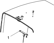
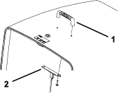
Installing the Hood Handle
Installing the Seat
Parts needed for this procedure:
| Seat—Model 30398 (optional kit) | 1 |
| Mechanical Seat Suspension Kit—Model 30312 (optional kit) or Pneumatic Seat Suspension Kit—Model 30313 (optional kit) | 1 |
The Groundsmaster 3280-D machine comes without the seat assembly. Obtain and install the optional seat (Model No. 30398) and the Mechanical Seat Suspension Kit (Model 30312) or the Pneumatic Seat Suspension Kit (Model 30313). Refer to the seat kit for the installation instructions.
Note: Refer to Installing the Manual Tube before mounting the seat to the seat suspension.
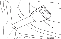
Installing the Seat Belt
Parts needed for this procedure:
| Seat belt | 1 |
| Bolts (7/16 x 1 inch) | 2 |
| Lock washer (7/16 inch) | 2 |
| Flat washer (7/16 inch) | 2 |
Note: You must mount the latch of the belt to the right side of the seat.
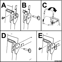
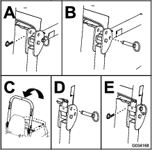
-
Assemble the end of each seat-belt latch to the holes in the back of the seat with 2 bolts (7/16 x 1 inch), flat washers (7/16 inch), and lock washers (7/16 inch) (Figure 6).
-
Torque the bolts to 61 to 75 N∙m (45 to 55 ft-lb).
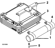
Installing the Manual Tube
Parts needed for this procedure:
| Manual tube | 1 |
| R-clamp | 2 |
-
Remove the manual tube and R-clamps secured to the seat plate.
Note: Discard the 2 mounting bolts and flat washers.
-
Remove the 2 nuts and vinyl caps (if previously installed) securing the upper seat bracket to the left side of the seat suspension (Figure 7).
-
Loosely mount the R-clamps to the seat bracket studs with the 2 nuts previously removed (Figure 7).
Note: Position the R-clamps under the seat-suspension tabs.
-
Install the manual tube into the R-clamps and tighten the nuts (Figure 7).
-
Insert the vinyl caps onto the seat bracket studs.
Adjusting the Roll Bar
-
Remove the hairpin cotter pins and remove the 2 pins from the roll bar (Figure 8).
-
Raise the roll bar to the upright position and install the 2 pins and secure them with the hairpin cotters (Figure 8).
Note: The roll bar is an effective safety device. Keep the roll bar in the raised and locked position. Lower the roll bar temporarily only when absolutely necessary.
Important: Do not wear the seat belt when the roll bar is in the down position.
Activating and Charging the Battery
Adding Electrolyte to the Battery
Warning
Battery electrolyte contains sulfuric acid, which is lethal if consumed and causes severe burns.
-
Do not drink electrolyte and avoid contact with skin, eyes, or clothing. Wear eye protection to shield your eyes and rubber gloves to protect your hands.
-
Fill the battery where clean water is always available for flushing the skin.
Important: Use only electrolyte with a specific gravity of 1.265 to initially fill battery.
-
Remove the battery from the machine.
Important: Do not add electrolyte while the battery is in the machine. You could spill it, causing corrosion.
-
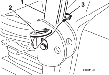
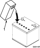
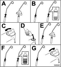
Clean the top of the battery and remove the vent caps (Figure 9).

-
Carefully fill each cell with electrolyte until it covers the plates with about 6 mm (1/4 inch) of fluid (Figure 10).
-
Allow the plates to soak in the electrolyte for 20 to 30 minutes.
Note: Add electrolyte as necessary to bring the electrolyte level to 6 mm (1/4 inch) of the bottom of the fill well (Figure 10).
Warning
Charging the battery produces gasses that can explode.
Never smoke near the battery and keep sparks and flames away from battery.
Charging the Battery
-
Connect a 3 to 4 A battery charger to the battery posts. Charge the battery at a rate of 3 to 4 amps until the specific gravity of the electrolyte is 1.250 or higher and the temperature of the battery is at least 16°C (60°F), with all cells freely discharging gas.
-
When the battery is charged, disconnect the charger from the electrical outlet and then disconnect the charger from the battery posts.
Note: Incomplete charging may result in gassing of the battery and the overflow of battery acid, causing corrosive damage to the machine.
Warning
Battery posts, terminals, and related accessories contain lead and lead compounds, chemicals known to the State of California to cause cancer and reproductive harm. Wash hands after handling.
Installing the Battery to the Machine
Warning
Battery terminals or metal tools could short against metal tractor components causing sparks. Sparks can cause the battery gasses to explode, resulting in personal injury.
-
When removing or installing the battery, do not allow the battery terminals to touch any metal parts of the tractor.
-
Do not allow metal tools to short between the battery terminals and metal parts of the tractor.
-
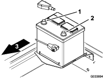
Install the battery into the machine.
-
Install the positive-battery cable (red) to the positive (+) terminal, and slide the rubber boot over the positive terminal (Figure 11).
Warning
Incorrect battery cable routing could damage the machine and cables, causing sparks. Sparks can cause the battery gasses to explode, resulting in personal injury.
-
Connect the cables to the correct battery post.
-
Always disconnect the negative (black) battery cable before disconnecting the positive (red) cable.
-
Always connect the positive (red) battery cable before connecting the negative (black) cable.
Note: Route the battery cables away from all sharp edges or moving parts.
-
-
Install the negative-battery cable (black) to the negative (-) terminal of the battery (Figure 11).
Checking the Fluid Levels
-
Check the engine-oil level before and after first starting the engine; refer to Checking the Engine-Oil Level.
-
Check the level of the rear-axle lubricant (4-wheel drive machines only) before first starting the engine; refer to Checking the Rear Axle Lubricant.
-
Check the level of the bidirectional clutch lubricant (4-wheel drive machines only) before first starting the engine; refer toChecking the Bidirectional Clutch Lubricant.
-
Check the coolant level before first starting the engine; refer toChecking the Cooling System and Coolant Level.
-
Check the level of the hydraulic fluid before first starting the engine; refer to Checking the Hydraulic System and Fluid Level.
Checking the Tire Pressure
Check the tire pressure; refer to Checking the Air Pressure in the Tires.
Important: Maintain pressure in all tires to ensure a good quality-of-cut and proper machine performance. Do not underinflate the tires.
Installing the Rear Weights
Parts needed for this procedure:
| Rear weight kit(s)—as needed | - |
This machine alone complies with EN ISO 5395:2013 and ANSI B71.4-2017 standard when equipped with factory installed rear weight—98 kg (215 lb) on Model 30344 (2WD machines) and 23 kg (50 lb) on Model 30345 (4WD machines). When you equip the machine with the listed attachments, use Table 1 to determine the additional weight required to maintain standards compliance. Order parts from your authorized Toro distributor.
Note: Before installing any third-party kits, contact your authorized Toro distributor.
| Attachments | Additional Rear Weight Required | Left Side Weight Required | Weight Part Number | Weight Description | Qty. |
|---|---|---|---|---|---|
| 52 inch Side Discharge Deck | 0 kg (0 lb) | 0 kg (0 lb) | - | - | - |
| 52 inch Side Discharge Deck with 15 cu. ft. Hopper | 0 kg (0 lb) | 66 kg (145 lb)* | *77-6700 | 34 kg (75 lb) Wheel Weight | 1 |
| 92-9670 | Bracket Kit | 1 | |||
| 24-5780 | Rear Weight Kit | 1 | |||
| 60 inch Side Discharge Deck | 16 kg (35 lb)** | 0 kg (0 lb) | 24-5790 | Rear Weight, 16 kg (35 lb) | 1 |
| or | 60-9870 | Bolt (1/2 x 4-1/2 inches) | 2 | ||
| 62 inch Base Deck with Rear Discharge Kit | 3253-7 | Lock washer (1/2 inch) | 2 | ||
| or | 3217-9 | Nut (1/2 inch) | 2 | ||
| 62 inch Side Discharge Deck | |||||
| 60 inch Side Discharge Deck with 15 cu. ft. Hopper | 16 kg (35 lb) | 34 kg (75 lb)* | *77-6700 | 34 kg (75 lb) Wheel Weight | 1 |
| 24-5790 | Rear Weight, 16 kg (35 lb) | 1 | |||
| 60-9870 | Bolt (1/2 x 4-1/2 inches) | 2 | |||
| 3253-7 | Lock washer (1/2 inch) | 2 | |||
| 3217-9 | Nut (1/2 inch) | 2 | |||
| 62 inch Side Discharge Deck with 15 cu. ft. Hopper | 0 kg (0 lb) | 39 kg (85 lb) | 132-8149 | 23 kg (50 lb) Wheel Weight | 1 |
| (add both weights to left front wheel) | 4 | ||||
| 325–18 | Bolt | ||||
| (for wheel weights) | |||||
| 92–9670 | Bracket Kit | 1 | |||
| 24–5790 | Rear Weight, 16 kg (35 lb) | 1 | |||
| 60-9870 | Bolt (1/2 x 2–1/4 inches) | 2 | |||
| 3253-7 | Lock washer (1/2 inch) | 2 | |||
| 3217-9 | Nut (1/2 inch) | 2 | |||
| 72 inch (4 casters) Side Discharge Deck | 32 kg (70 lb) | 0 kg (0 lb) | 24-5780 | Rear Weight Kit | 1 |
| or | |||||
| 72 inch Base Deck with Rear Discharge Kit or Guardian Kit | |||||
| or | |||||
| 72 inch (4 casters) Guardian Recycler Deck | |||||
| Pro Force Blower with Adapter Kit—Not CE compliant | 95 kg (210 lb) | 0 kg (0 lb) | 24–5780 | Rear Weight Kit | 3 |
| Winter Cab and Toro V-plow | 64 kg (140 lb) | 0 kg (0 lb) | 24-5780 | Rear Weight Kit | 2 |
| Winter Cab and ***Erskine Snowthrower | 111 kg (245 lb) | 0 kg (0 lb) | 24–5790 | Rear Weight, 16 kg (35 lb) | 1 |
| 24-5780 | Rear Weight Kit | 3 | |||
| 60-9870 | Bolt (1/2 x 2–1/4 inches) | 2 | |||
| 3253-7 | Lock washer (1/2 inch) | 2 | |||
| 3217-9 | Nut (1/2 inch) | 2 | |||
| Winter Cab and ***MB Rotary Broom | 175 kg (385 lb) | 0 kg (0 lb) | 24–5790 | Rear Weight, 16 kg (35 lb) | 1 |
| 24-5780 | Rear Weight Kit | 5 | |||
| 60-9870 | Bolt (1/2 x 2–1/4 inches) | 2 | |||
| 3253-7 | Lock washer (1/2 inch) | 2 | |||
| 3217-9 | Nut (1/2 inch) | 2 |
*Requires a 34 kg (75 lb) wheel weight on the left wheel—included with the 0.4 m3(15 ft3) hopper
**Requires a 16 kg (35 lb) rear weight when the universal sunshade is attached to the machine
***Third party attachment—complies with ANSI B71.3-2005
Adjusting the Weight Transfer of the Mower Deck
You can change the hydraulic pressure used to transfer the weight of the mower deck to the traction unit by adjusting weight-transfer valve of the lift manifold. For best cutting performance, adjust the weight-transfer valve so that any bouncing motion of the mower deck is minimal over uneven turf, but also adjust the weight-transfer valve so that the mower deck does not ride heavily over flat terrain.
-
To improve the contour-tracking performance of the cutting deck as you operate the machine over uneven turf, decrease the weight-transfer (hydraulic) pressure at the lift manifold.
Note: If the casters of the mower deck float above the ground, the hydraulic pressure of the weight transfer valve is set at too high.
-
When you are cutting flat turf, when the cutting deck is scalping the grass, or if the quality of cut is uneven from side to side, increase the weight-transfer pressure at the lift manifold.
Note: Increasing weight-transfer pressure also transfers the weight from the casters of the cutting deck to the wheels of the traction unit, thereby improving the traction of the traction unit.
Adjust the weight-transfer pressure as follows:
-
Park the machine on a level surface, engage the parking brake, lower the cutting deck, shut off the engine, and remove the key from the key switch.
-
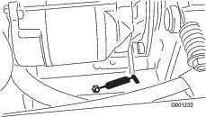
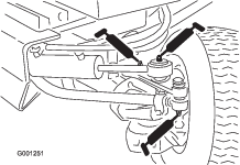
Locate the lift manifold from under the machine, inboard the right frame channel, behind the front axle (Figure 12).
-
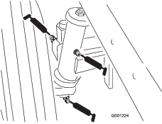
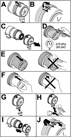
Connect a pressure gauge to the test port at the rear of the lift manifold (Figure 13).
-
At the front of the lift manifold, remove the cap from the weight-transfer spool (Figure 13).
-
Loosen the jam nut at the bottom of the weight-transfer spool (Figure 13).
-
Start the engine and set the throttle to HIGH IDLE.
-
Use a hex-socket wrench to adjust the lift valve of the weight-transfer spool until the gauge indicates the desired pressure; refer to the chart that follows for the recommended pressure setting for the cutting deck.
-
Rotate the adjusting screw clockwise to increase the pressure.
-
Rotate the adjusting screw counterclockwise to decrease the pressure.
Cutting Deck Weight-Transfer Pressure 52 inch Side Discharge Deck (Model 30555) 827 kPa (120 psi) 60 inch Side Discharge Deck (Model 30366) or 62 in Base Deck (Model 30403) or 62 in Side Discharge Deck (Model 30551) 1620 kPa (235 psi) 72 inch Side Discharge Deck (Model 31336) or 72 in Base Deck (Model 30404) or 72 in Guardian Recycler Deck (Model 31335) 1930 kPa (280 psi) -
-
Shut off the engine.
-
Tighten the jam nut at the bottom of the weight-transfer spool, and torque the nut to 13-16 N∙m (10-12 ft-lb).
-
Remove the pressure gauge from the test port.
Using the Hardware for Attachments
Parts needed for this procedure:
| Roll pin | 1 |
| Bolt (5/16 x 1-3/4 inches) | 2 |
| Locknut (5/16 inch) | 2 |
| Cylinder pin | 2 |
| Cotter pin (3/16 x 1-1/2 inches) | 4 |
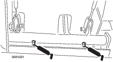
| Brake-return springs | 2 |
-
Save the roll pin, bolts (5/16 x 1-3/4 inches), and locknuts (5/16 inch) to secure the universal shaft to an implement.
-
Save the cylinder pin and cotter pin (3/16 x 1-1/2 inches) to secure the deck lift arms to the lift cylinder.
-
Save the brake return springs to mount the deck lift arms.
Product Overview
Traction Pedal
The traction pedal (Figure 15) makes the machine move forward and rearward. Using the heel and toe of the right foot, press the top of the pedal to move forward and the bottom of the pedal to move rearward. The ground speed is proportionate to how far you press the pedal. For maximum ground speed, you must fully press traction pedal while throttle is in the FAST position. The maximum speed forward is approximately 16 kp/h (10 mph). To get maximum power under heavy load or when ascending a hill, have the throttle in the FAST position while pressing traction pedal slightly to keep the engine speed (rpm) high. When the engine speed begins to decrease, release the traction pedal slightly to allow the engine speed to increase.
Tilt-Steering Control
The tilt-steering control is a lever on the right side of the steering column (Figure 16). Pull the lever rearward to adjust the steering wheel to the desired operating position and push the lever forward to lock the adjustment.
Caution
Raising the deck can expose you to rotating blades, and contact with rotating blades can cause serious injury.
Never raise the deck while the blades are rotating.
Brakes
Service Brakes
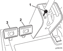
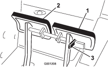
The left and right brake pedals (Figure 17) connect to the left and right front wheels. Since both brakes work independently of each other, you can use the brakes to turn sharply or to increase traction if 1 wheel tends to slip while operating on certain slope conditions. However, you can damage wet grass or soft turf whenever you use the brakes to turn sharply. To stop the machine quickly, press both brake pedals together. Always lock the brakes together when transporting the machine (Figure 18).
Parking Brake
Whenever you shut off the engine, engage the parking brake to prevent the machine from accidentally moving. To engage the parking brake, push the lock arm (Figure 18) on the left brake pedal so that it locks together with the right pedal. Then push down fully on both pedals, pull the parking brake knob out (Figure 17), and release the pedals. To release the parking brake, press both pedals until the parking-brake knob retracts. Before starting the engine, release the lock arm from the left brake pedal so that both pedals work independently with each front wheel.
Ignition Switch
The ignition switch has 3 positions: OFF, ON/PREHEAT, and START.
Lift Switch
The lift switch (Figure 19) raises and lowers the deck. Pressing the switch forward, into the DETENT position, lowers the deck and allows the deck to float. Pressing the switch backward raises the deck. Raise the deck whenever you transport the machine between locations. Lower the deck whenever you are not using the machine.
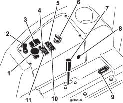
PTO Switch
Pull up the knob for the PTO switch to ON position to run the electric PTO clutch (Figure 19). Push down the knob to the OFF position to shut off the electric PTO clutch. The only time you should set the PTO switch to the ON position is when the PTO implement is in the operating position (down) and you are ready to begin operation.
Note: If you leave the operator’s seat while the PTO switch is in the ON position, the machine will automatically shut off the engine; refer to Resetting the PTO Function.
Fuel Gauge
The fuel gauge (Figure 20) indicates the level of fuel remaining in the fuel tank.
Throttle Lever
Use the throttle lever (Figure 19) to control the engine speed. Moving the throttle lever forward toward the FAST position increases the engine speed. Moving the throttle lever rearward toward the SLOW position decreases the engine speed. The throttle lever controls the speed of the blades and, in conjunction with traction pedal, controls ground speed of the machine. The detent is located at the HIGH-IDLE position.
Hour Meter
The hour meter (Figure 19) records and displays accumulated hours of engine operation.
Coolant Temperature-Warning Light
When the engine coolant temperature rises above normal operating limit, the coolant temperature-warning light (Figure 19) illuminates and the machine stops operation of the implement. If the coolant temperature rises another 7°C (20°F) after the temperature-warning light illuminates, the engine shuts off. Operate the engine at low idle to allow the coolant to return to the normal-operating range. If the warning light continues to illuminate, shut off the engine and determine the cause of the high coolant temperature.
Glow-Plug Indicator
When glow-plug indicator illuminates, the glow plugs are energized (Figure 19).
Charge Indicator
The charge indicator illuminates if electrical charging system is operating above or below the normal operating range (Figure 19). Check and/or repair the electrical charging system.
Oil-Pressure Warning Light
The oil-pressure warning light glows if the engine-oil pressure drops below a safe level (Figure 19). If the oil pressure is low, shut off the engine and determine the cause. Repair the engine-oil system before you start the engine again.
Lift-Lock Lever
Use the lift-lock lever to secure the lift switch (Figure 19), to the RAISE-DECK position, when performing maintenance on the deck or when transporting between mowing locations.
Note: Specifications and design are subject to change without notice.
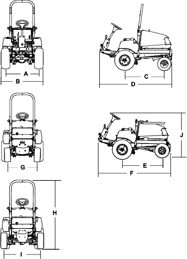
| Description | Figure 21 reference | Dimension or Weight | |
| Height with roll bar raised | H | 237 cm (93-1/2 inches) | |
| Height with roll bar lowered | J | 127 cm (50 inches) | |
| Overall length (2-wheel drive) | D | 213 cm (84 inches) | |
| Overall length (4-wheel drive) | F | 218 cm (86 inches) | |
| Overall width | B | 121 cm (47-1/2 inches) | |
| Wheel-base length (2-wheel drive) | C | 117 cm (46 inches) | |
| Wheel-base length (4-wheel drive) | E | 119 cm (47 inches) | |
| Front-wheel tread width | A | 119 cm (47 inches) | |
| Rear-wheel tread width | |||
| 2-wheel drive | G | 86 cm (34 inches) | |
| 4-wheel drive | I | 102 cm (40 inches) | |
| Ground clearance | 17 cm (6-1/2 inches) | ||
| Net Weight (2-wheel drive) | 635 kg (1,400 lb) | ||
| Net Weight (4-wheel drive) | 794 kg (1,751 lb) | ||
Attachments/Accessories
A selection of Toro approved attachments and accessories is available for use with the machine to enhance and expand its capabilities. Contact your Authorized Service Dealer or authorized Toro distributor or go to www.Toro.com for a list of all approved attachments and accessories.
To ensure optimum performance and continued safety certification of the machine, use only genuine Toro replacement parts and accessories. Replacement parts and accessories made by other manufacturers could be dangerous, and such use could void the product warranty.
Operation
Note: Determine the left and right sides of the machine from the normal operating position.
Before Operation
Before Operation Safety
General Safety
-
Park the machine on a level surface; engage the parking brake; shut off the engine; remove the key; and wait for all movement to stop before leaving the machine.
-
Never allow children or untrained people to operate or service the machine. Local regulations may restrict the age of the operator. The owner is responsible for training all operators and mechanics.
-
Become familiar with the safe operation of the equipment, operator controls, and safety signs.
-
Know how to stop the machine and shut off the engine quickly.
-
Check that operator-presence controls, safety switches, and shields are attached and functioning properly. Do not operate the machine unless they are functioning properly.
-
Before mowing, always inspect the machine to ensure that the blades, blade bolts, and cutting assemblies are in good working condition. Replace worn or damaged blades and bolts in sets to preserve balance.
-
Inspect the area where you will use the machine and remove all objects that the machine could throw.
Fuel Safety
-
Use extreme care in handling fuel. It is flammable, and its vapors are explosive.
-
Extinguish all cigarettes, cigars, pipes, and other sources of ignition.
-
Use only an approved fuel container.
-
Do not remove the fuel cap or fill the fuel tank while the engine is running or hot.
-
Do not add or drain fuel in an enclosed space.
-
Do not store the machine or fuel container where there is an open flame, spark, or pilot light, such as on a water heater or other appliance.
-
If you spill fuel, do not attempt to start the engine; avoid creating any source of ignition until the fuel vapors have dissipated.
Checking the Machine Daily
Check the following machine systems each day before operating the machine:
-
Air Cleaner Indicator; refer to Checking the Air Cleaner Indicator
-
Engine oil; refer to Checking the Engine-Oil Level
-
Coolant system; refer to Checking the Cooling System and Coolant Level
-
Hood screen and radiator; refer to Checking the Hood Screen and Radiator for Debris
-
Hydraulic system; refer to Checking the Hydraulic System and Fluid Level
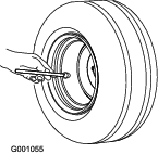
Checking the Air Pressure in the Tires
Tire air pressure specification (front and rear tires): 138 kPa (20 psi).
Danger
Low tire pressure decreases machine side-hill stability. This could cause a rollover, which may result in personal injury or death.
Do not underinflate the tires.
Check the air pressure in the front and rear tires. Add or remove air as needed to set the air pressure in the tires to the tire air pressure specification.
Important: Maintain pressure in all tires to ensure a good quality of cut and proper machine performance.Check the air pressure in all the tires before operating the machine.
Checking the Interlock System
| Maintenance Service Interval | Maintenance Procedure |
|---|---|
| Before each use or daily |
|
The purpose of the safety interlock system is to prevent the engine from cranking or starting unless the traction pedal is in neutral and the PTO switch is in the OFF position. In addition, the engine should stop when
-
the PTO switch is set to the ON position and the operator off the seat;
-
the traction pedal is pressed with the operator off the seat;
-
the traction pedal pressed with the parking brake engaged.
Caution
If the safety-interlock switches are disconnected or damaged, the machine could operate unexpectedly, causing personal injury.
-
Do not tamper with the interlock switches.
-
Check the operation of the interlock switches daily and replace any damaged switches before operating the machine.
-
Move PTO switch to OFF position and remove your foot from traction pedal.
-
Rotate the key switch to the START position. If the engine cranks, proceed to step 3.
Note: If engine does not crank, there may be a malfunction in the safety-interlock system.
-
With the engine running, raise off the seat and set the PTO switch to the ON position . The engine should shut off within 2 seconds. If the engine shuts off, proceed to step 4.
Important: If engine does not shut off, there is a malfunction in the safety-interlock system.
-
With the engine running and the PTO switch set to the OFF position, raise off the seat and press the traction pedal. The engine should shut off within 2 seconds. If engine shuts off, proceed to step 5.
Important: If engine does not shut off, there is a malfunction in the safety-interlock system.
-
Engage the parking brake. With the engine running and the PTO switch set to the ON position, press the traction pedal. The engine should shut off within 2 seconds. If engine shuts off, the switch is operating correctly; the interlock system is ready for machine operation.
Important: If engine does not shut off, there is a malfunction in the safety-interlock system.
Adding Fuel
Fuel Specification
Important: Use only low sulphur or ultra-low sulphur diesel fuel.Failure to observe the following cautions may damage the engine.
-
Never use kerosene or gasoline instead of diesel fuel.
-
Never mix kerosene or used engine oil with the diesel fuel.
-
Never keep fuel in containers with zinc plating on the inside.
-
Do not use fuel additives.
-
Use only clean, fresh diesel fuel or biodiesel fuels.
-
Purchase fuel in quantities that you can use within 180 days to ensure fuel freshness.
Petroleum Diesel
Cetane rating: 40 or higher
Sulfur content: Low sulphur (<500 ppm) or Ultra-low sulfur (<15 ppm)
Use summer-grade diesel fuel (No. 2-D) at temperatures above -7°C (20°F) and winter-grade fuel (No. 1-D or No. 1-D/2-D blend) below that temperature.
Note: Use of winter-grade fuel at lower temperatures provides lower flash point and cold flow characteristics which eases starting and reduces fuel filter plugging.Using summer-grade fuel above -7°C (20°F) contributes toward longer fuel pump life and increased power compared to winter-grade fuel.
Biodiesel
This machine can also use a biodiesel blended fuel of up to B20 (20% biodiesel, 80% petroleum diesel).
Sulfur content: Ultra-low sulfur (<15 ppm)
Biodiesel fuel specification: ASTM D6751 or EN14214
Blended fuel specification: ASTM D975, EN590, or JIS K2204
Important: The petroleum diesel portion must be ultra-low sulfur.
Observe the following precautions:
-
Biodiesel blends may damage painted surfaces.
-
Use B5 (biodiesel content of 5%) or lesser blends in cold weather.
-
Monitor seals, hoses, gaskets in contact with fuel as they may degrade over time.
-
Fuel filter plugging may occur for period after converting to biodiesel blends.
-
Contact your authorized Toro distributor if you wish for more information on biodiesel.
Filling the Fuel Tank
Fuel tank capacity: 72 L (12.8 US gallons)
Note: If possible, fill the fuel tank after each use; this minimizes condensation buildup inside the fuel tank.
Adjusting the Roll Bar
Warning
A rollover can cause injury or death.
-
Keep the roll bar in the raised locked position.
-
Use the seat belt.
-
Secure the seat with the seat latch.
Warning
There is no rollover protection when the roll bar is in the down position.
-
Do not operate the machine on uneven ground or on a hill side with the roll bar in the down position.
-
Lower the roll bar only when absolutely necessary.
-
Do not wear the seat belt when the roll bar is in the down position.
-
Drive slowly and carefully.
-
Raise the roll bar as soon as clearance permits.
-
Check carefully for overhead clearances (i.e., branches, doorways, electrical wires) before driving under any objects and do not contact them.
Important: Always use the seat belt when the roll bar is in the raised and locked position. Do not use the seat belt when the roll bar is in the lowered position.
Lowering the Roll Bar
Important: Lower the roll bar only when absolutely necessary.
Important: Secure the seat with the seat latch.
-
Park the machine on a level surface, engage the parking brake, lower the cutting deck, shut off the engine, and remove the key from the key switch.
-
Remove the cotter pins and pins from the roll bar (Figure 24).
-
Lower the roll bar and secure it in place with the pins and cotter pins (Figure 24).
Raising the Roll Bar
Adjusting the Tilt-Steering Control
-
Remove the knob from the parking brake and the screws from the steering-column cover (Figure 26).
-
Slide the cover up the steering shaft to expose the pivot bracket (Figure 27).
-
Loosen the small nut and rotate the pivot bracket until it tightens the large nut below it (Figure 27).
-
Tighten the small nut.
-
Install the steering-column cover and the parking-brake knob.
During Operation
During Operation Safety
General Safety
-
The owner/operator can prevent and is responsible for accidents that may cause personal injury or property damage.
-
Wear appropriate clothing, including eye protection; long pants; substantial, slip-resistant footwear; and hearing protection. Tie back long hair and do not wear loose jewelry.
-
Use your full attention while operating the machine. Do not engage in any activity that causes distractions; otherwise, injury or property damage may occur.
-
Do not operate the machine while ill, tired, or under the influence of alcohol or drugs.
-
Never carry passengers on the machine and keep bystanders and pets away from the machine during operation.
-
Operate the machine only in good visibility to avoid holes or hidden hazards.
-
Before you start the engine, ensure that all drives are in neutral, the parking brake is engaged, and you are in the operating position.
-
Keep your hands and feet away from rotating parts. Keep clear of the discharge opening at all times.
-
Look behind and down before backing up to be sure of a clear path.
-
Use care when approaching blind corners, shrubs, trees, or other objects that may obscure your vision.
-
Stop the blades whenever you are not mowing.
-
Stop the machine, remove the key, and wait for all moving parts to stop before inspecting the attachment after striking an object or if there is an abnormal vibration in the machine. Make all necessary repairs before resuming operation.
-
Slow down and use caution when making turns and crossing roads and sidewalks with the machine. Always yield the right-of-way.
-
Disengage the drive to the cutting unit, shut off the engine, remove the key, and wait for all moving parts to stop before adjusting the height of cut (unless you can adjust it from the operating position).
-
Never run an engine in an area where exhaust gasses are enclosed.
-
Never leave a running machine unattended.
-
Before leaving the operating position (including to empty the catchers or to unclog the chute), do the following:
-
Park the machine on level ground.
-
Disengage the power takeoff and lower the attachments.
-
Engage the parking brake.
-
Shut off the engine and remove the key.
-
Wait for all moving parts to stop.
-
-
Do not operate the machine when there is the risk of lightning.
-
Do not use the machine as a towing vehicle.
-
Use accessories, attachments, and replacement parts approved by The Toro® Company only.
Rollover Protection System (ROPS) Safety
-
Do not remove the ROPS from the machine.
-
Ensure that the seat belt is attached and that you can release it quickly in an emergency.
-
Check carefully for overhead obstructions and do not contact them.
-
Keep the ROPS in safe operating condition by thoroughly inspecting it periodically for damage and keeping all the mounting fasteners tight.
-
Replace damaged ROPS components. Do not repair or alter them.
Machines with a Foldable Roll Bar
-
Always use the seat belt with the roll bar in the raised position.
-
The ROPS is an integral safety device. Keep a folding roll bar in the raised and locked position, and use the seat belt when operating the machine with the roll bar in the raised position.
-
Lower a folding roll bar temporarily only when necessary. Do not wear the seat belt when the roll bar is folded down.
-
Be aware that there is no rollover protection when a folded roll bar is in the down position.
-
Check the area that you will be mowing and never fold down a folding roll bar in areas where there are slopes, drop-offs, or water.
Slope Safety
-
Slopes are a major factor related to loss of control and rollover accidents, which can result in severe injury or death. You are responsible for safe slope operation. Operating the machine on any slope requires extra caution.
-
Evaluate the site conditions to determine if the slope is safe for machine operation, including surveying the site. Always use common sense and good judgment when performing this survey.
-
Review the slope instructions listed below for operating the machine on slopes and to determine whether you can operate the machine in the conditions on that day and at that site. Changes in the terrain can result in a change in slope operation for the machine.
-
Avoid starting, stopping, or turning the machine on slopes. Avoid making sudden changes in speed or direction. Make turns slowly and gradually.
-
Do not operate a machine under any conditions where traction, steering, or stability is in question.
-
Remove or mark obstructions such as ditches, holes, ruts, bumps, rocks, or other hidden hazards. Tall grass can hide obstructions. Uneven terrain could overturn the machine.
-
Be aware that operating the machine on wet grass, across slopes, or downhill may cause the machine to lose traction. Loss of traction to the drive wheels may result in sliding and a loss of braking and steering.
-
Use extreme caution when operating the machine near drop-offs, ditches, embankments, water hazards, or other hazards. The machine could suddenly roll over if a wheel goes over the edge or the edge caves in. Establish a safety area between the machine and any hazard.
-
Identify hazards at the base of the slope. If there are hazards, mow the slope with a pedestrian-controlled machine.
-
If possible, keep the cutting unit(s) lowered to the ground while operating on slopes. Raising the cutting unit(s) while operating on slopes can cause the machine to become unstable.
-
Use extreme caution with grass-collection systems or other attachments. These can change the stability of the machine and cause a loss of control. Always keep the machine in gear when going down slopes. Do not coast downhill (applicable only to gear-drive units).
Starting the Engine
Important: You might need to bleed the fuel system in any of the following situations: initially starting up a new machine, the engine no longer running due to lack of fuel, or fuel system components replaced or serviced.
-
Raise the roll bar and lock it into place.
-
Sit on the seat and fasten the seat belt.
-
Engaged the parking brake and the set the PTO switch to the OFF position.
-
Remove your foot from traction pedal and ensure that it is in neutral.
-
Rotate the key switch to the ON/PREHEAT position.
Note: An automatic timer then controls the preheat for 6 seconds.
-
After preheating, rotate the key switch to the START position, crank the engine for no longer than 15 seconds, and release the key when the engine starts.
Note: If the engine is still cold, preheat it more by turning the key to the OFF position, then to the ON/PREHEAT position. Repeat this process as required.
-
Move the throttle to idle speed or partial throttle and run the engine until it warms up.
Important: When you start the engine for the first time; or after you change the engine oil or overhaul the engine, transmission, or axle; operate the machine in forward and reverse for 1 to 2 minutes. Also, operate the lift lever and PTO lever to ensure that all parts are properly operating. Turn the power-steering wheel to the left and right to check the steering response. Then shut the engine off, check the fluid levels, and check for oil leaks, loose parts, and any other malfunctions.
Shutting Off the Engine
-
Move the throttle control rearward to the SLOW position.
-
Move the PTO switch to the OFF position.
-
Rotate key switch to the OFF position.
-
Remove the key from the switch to prevent accidental starting.
Resetting the PTO Function
Note: If you leave the operator’s seat while the PTO switch is in the ON position, the machine will automatically shut off the engine.
Perform the following to reset the PTO function:
-
Push down the PTO switch knob; refer to Figure 19 and PTO Switch.
-
Start the engine; refer to Starting the Engine.
-
Pull up the PTO switch knob; refer to Figure 19 and PTO Switch.
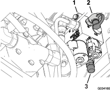
Purging the Fuel-Injection Pump
-
Park the machine on a level surface.
-
Engage the parking brake.
-
Ensure that the fuel tank is at least half full.
-
Unlatch and raise the hood.
-
Open the air-bleed screw on the fuel-injection pump (Figure 28).
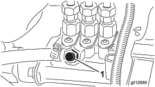
-
Rotate the key switch to the ON position.
The electric fuel pump begins forcing air out around the air-bleed screw.
-
Leave the key switch in the ON position until a solid stream of fuel flows out around the screw.
-
Tighten the screw and rotate key switch to the OFF position.
Note: The engine should start after you perform this procedure. However, if the engine does not start, air may be trapped between the injection pump and the injectors; refer to Purging the Air from the Fuel-Injector Tubing.
-
Wipe clean any fuel that has accumulated around the injection pump.
Operating Tips
-
Practice driving before operating the machine, because it has a hydrostatic transmission and its characteristics are different than some turf-maintenance machines.
-
To maintain enough power for the machine and deck while mowing, regulate the traction pedal to keep the engine speed (rpm) high and constant. Decrease the ground speed as the load on the cutting blades increases; increase the ground speed as the load on the blades decreases. This allows the engine, working with the transmission, to sense the proper ground speed while maintaining a high blade-tip speed necessary for good quality of cut. Therefore, allow the traction pedal to move upward as the engine speed decreases, and press pedal slowly as the speed increases. When driving from 1 work area to another (with no load and the deck raised), have throttle in the FAST position and press the traction pedal slowly but fully to attain the maximum ground speed.
-
Lock the brake pedals together before transporting the machine.
-
You can use the brakes to assist in turning the machine; but, use them carefully on soft or wet grass because doing so may damage the turf. You can also use the brakes to control the direction of the deck when trimming along fences or similar objects. A third way you can use the brakes is to maintain traction. For example; in some slope conditions, the uphill wheel slips and loses traction. If this happens, press the uphill brake pedal gradually and intermittently until the uphill wheel stops slipping, thus increasing the traction on the downhill wheel. If you do not want independent braking, set the lever on left brake pedal with right pedal. This provides simultaneous braking at both wheels.
-
Before shutting off the engine, move all controls to the NEUTRAL position and move the throttle to the SLOW position. Rotate the key switch to the OFF position to shut off the engine.
-
The engine does not run when the engine coolant is in over temperature condition. Let the engine and cooling system cool, and check the cooling system; refer to Checking the Cooling System and Coolant Level.
After Operation
After Operation Safety
-
Clean grass and debris from the cutting units, mufflers, and engine compartment to help prevent fires. Clean up oil or fuel spills.
-
If the cutting units are in the transport position, use the positive mechanical lock (if available) before you leave the machine unattended.
-
Allow the engine to cool before storing the machine in any enclosure.
-
Remove the key and shut off the fuel (if equipped) before storing or transporting the machine.
-
Never store the machine or fuel container where there is an open flame, spark, or pilot light, such as on a water heater or on other appliances.
-
Keep all parts of the machine in good working condition and all hardware tightened, especially blade-attachment hardware.
-
Maintain and clean the seat belt(s) as necessary
-
Replace all worn or damaged decals.
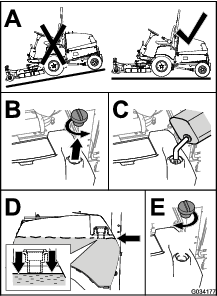
Pushing or Towing the Machine
In an emergency, you can move the machine a very short distance by actuating the bypass valve in the hydraulic pump and pushing or towing the machine.
Important: Do not push or tow the machine faster than 3 to 4.8 km/h (2 to 3 mph). If you push or tow at a faster speed, internal transmission damage may occur. If you must move the machine a considerable distance, transport it on a truck or trailer.
Important: The bypass valve must be open whenever you push or tow the machine. Close the valve once you have pushed or towed the machine to the desired location.
Opening the Bypass Valve
-
Remove the seat and seat plate; refer to Removing the Seat and Seat Plate.
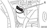
-
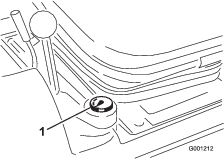
Locate the control knob for the bypass valve at the left side of the hydraulic pump (Figure 29).
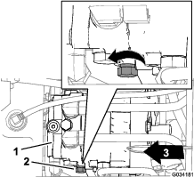
-
Rotate the control knob 3 turns counterclockwise (Figure 29).
Important: Do not rotate the control knob more that 3 turns.
-
Push or tow the machine.
Closing the Bypass Valve
Note: Close the bypass before you start the engine.
-
Finish pushing or towing the machine.
-
Locate the control knob for the bypass valve at the left side of the hydraulic pump (Figure 29).
-
Rotate the control knob (Figure 29) clockwise until you feel resistance, indicating that the bypass valve is closed.
-
Install the seat and seat plate; refer to Installing the Seat and Seat Plate.
Hauling the Machine
-
Remove the key and shut off the fuel (if equipped) before storing or transporting the machine.
-
Use care when loading or unloading the machine into a trailer or a truck.
-
Use full-width ramps for loading the machine into a trailer or a truck.
-
Tie the machine down securely.
Maintenance
Important: Refer to your engine owner’s manual for additional maintenance procedures.
Note: Download a free copy of the electrical or hydraulic schematic by visiting www.Toro.com and searching for your machine from the Manuals link on the home page.
Note: Determine the left and right sides of the machine from the normal operating position.
Maintenance Safety
-
Before adjusting, cleaning, repairing, or leaving the machine, do the following:
-
Park the machine on a level surface.
-
Move the throttle switch to the low-idle position.
-
Disengage the cutting units.
-
Lower the cutting units.
-
Ensure that the traction is in neutral.
-
Engage the parking brake.
-
Shut off the engine and remove the key.
-
Wait for all moving parts to stop.
-
Allow machine components to cool before performing maintenance.
-
-
If the cutting units are in the transport position, use the positive mechanical lock (if available) before you leave the machine unattended.
-
If possible, do not perform maintenance while the engine is running. Keep away from moving parts.
-
Use jack stands to support the machine or components when required.
-
Carefully release pressure from components with stored energy.
Recommended Maintenance Schedule(s)
| Maintenance Service Interval | Maintenance Procedure |
|---|---|
| After the first hour |
|
| After the first 10 hours |
|
| After the first 50 hours |
|
| Before each use or daily |
|
| Every 50 hours |
|
| Every 150 hours |
|
| Every 200 hours |
|
| Every 400 hours |
|
| Every 1,500 hours |
|
| Monthly |
|
Pre-Maintenance Procedures
Caution
If you leave the key in the switch, someone could accidently start the engine and seriously injure you or other bystanders.
Remove the key from the switch before you perform any maintenance.
Accessing the Machine
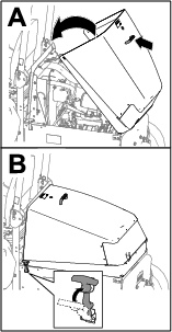
Opening the Hood
Closing the Hood
Accessing the Hydraulic Pump
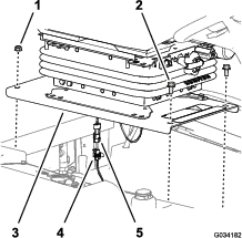
Removing the Seat and Seat Plate
-
Remove the 2 flange-head bolts (3/8 x 3/4 inch) at the that secure the front of the seat plate to the chassis of the machine (Figure 33).
-
Remove the 2 flange locknuts (3/8 inch) at the that secure the back of the seat plate to the chassis of the machine (Figure 33).
-
Partially lift the seat assembly.
-
Disconnect the 2-pin connector for the operator-presence switch harness from the 2-socket connector of the machine wire harness (Figure 33).
-
Remove the seat assembly from the machine.
Installing the Seat and Seat Plate
Install the seat once you have repaired the machine and closed the bypass valve for the hydraulic pump.
-
Align the seat assembly to the opening in the fuel tank.
-
Connect the 2-pin connector for the operator-presence switch harness into the 2-socket connector of the machine wire harness; refer to Figure 33 .
-
Align the rear holes in the seat plate (Figure 33) with the 2 carriage bolts (3/8 x 1 inch) in the radiator channel.
-
Assemble the seat plate (Figure 33) to the carriage bolts with the 2 flange locknuts (3/8 inch) that you removed in step 2 of Removing the Seat and Seat Plate.
-
Align the front holes in the seat plate (Figure 33) with the threads of the tank rods.
-
Assemble the seat plate (Figure 33) to the tank rods with the 2 flange-head bolts (3/8 x 3/4 inch) that you removed in step 1 of Removing the Seat and Seat Plate.
-
Torque the flange locknuts and flange-head bolts to 37 to 45 N∙m (27 to 33 ft-lb).
-
Check the interlock system; refer to Checking the Interlock System.
Lubrication
Greasing the Bearings and Bushings
| Maintenance Service Interval | Maintenance Procedure |
|---|---|
| Every 50 hours |
|
| Every 400 hours |
|
Grease specification: No. 2 lithium grease.
Important: Dusty and dirty operating conditions could cause dirt to get into the bearings and bushings, resulting in accelerated wear.
Note: Lubricate grease fitting immediately after every washing, regardless of interval specified.
-
Wipe grease fitting clean.
-
Pump grease into the bearing or bushing.
-
Wipe up excess grease.
The bearing and bushing lubrication points are as follows:
-
PTO universal shaft (Figure 34)
-
Lift-arm pivot bushings (Figure 35)
-
Brake pivot bushings (Figure 36)
-
Brake cables (drive wheel and brake pedal ends) (Figure 36)
-
PTO tension pivot (Figure 37)
-
Rear PTO bearing (Figure 37)
-
Rear wheel spindle bushings (Figure 38)
-
Steering-plate bushings (Figure 39)
-
Axle-pin bushing (Figure 39)
-
Drive shaft (3) (Figure 40)
Note: 4-wheel drive models only.

-
Tie-rod ends (2) (Figure 41)
-
Cylinder-rod ends (2) (Figure 41)
-
Steering pivots (2) (Figure 41)
-
Axle-pivot pin (Figure 41)
Note: Improper wash-down procedures negatively affect bearing life. Do not wash down the machine when it is still hot and avoid directing high-pressure or high-volume spray at the bearings.
Engine Maintenance
Engine Safety
-
Shut off the engine and remove the key before checking the oil or adding oil to the crankcase.
-
Do not change the governor speed or overspeed the engine.
Servicing the Air Cleaner
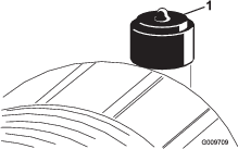
Checking the Air Cleaner Indicator
| Maintenance Service Interval | Maintenance Procedure |
|---|---|
| Before each use or daily |
|
-
Check the air-cleaner body for damage that could cause an air leak. Replace a damaged air-cleaner body. Check the whole intake system for leaks, damage, or loose hose clamps.
-
Replace the air cleaner element when the air-cleaner indicator (Figure 42) shows red. Do not over-clean the air-filter element.
-
Ensure that the cover seats correctly and seals with the air-cleaner body.
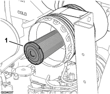
Replacing the Air Cleaner Elements
| Maintenance Service Interval | Maintenance Procedure |
|---|---|
| Every 50 hours |
|
| Every 400 hours |
|
Important: Avoid using high-pressure air that could force dirt through the filter and into the intake tract, causing damage. This cleaning process prevents debris from migrating into the intake when you remove the primary filter.
Important: Do not clean the used element to prevent the possibility of damaging the filter media. Inspect the new filter for shipping damage, checking the sealing end of the filter and the body. Do not use a damaged element.
Important: Ensure that the cover seats correctly and seals with the air-cleaner body.
-
Replace the primary air-cleaner element (Figure 43).
-
Check the air-cleaner safety filter for dust and debris (Figure 44).
Important: Never attempt to clean the safety filter (Figure 44). Replace the safety filter after every 3 primary filter services.
Note: Replace the air-cleaner safety filter if it dirty.
-
Reset the air-cleaner indicator if it shows red; refer to Checking the Air Cleaner Indicator.
Engine Oil Specification
-
Engine oil-type: API classification level: CH-4 or higher.
-
Engine oil viscosity:
-
Preferred oil: SAE 15W-40 (above 0°F)
-
Alternate oil: SAE 10W-30 or 5W-30 (all temperatures)
-
Note: Toro Premium Engine Oil is available from your distributor in either 15W-40 or 10W-30 viscosity. See the parts catalog for part numbers.
Checking the Engine-Oil Level
| Maintenance Service Interval | Maintenance Procedure |
|---|---|
| Before each use or daily |
|
The engine is shipped with oil in the crankcase.
Note: The best time to check the engine oil is when the engine is cool before it has been started for the day. If you have already run the engine, allow the oil to drain back down to the sump for at least 10 minutes before checking.
-
Park the machine on a level surface, engage the parking brake, lower the cutting deck, shut off the engine, and remove the key from the key switch.
-
Open the hood.
-
Check the engine-oil level as shown in Figure 45.
-
If the oil level is at or below the ADD mark on the dipstick, remove the oil-fill cap (Figure 46) and add oil to bring the oil level to the FULL mark on the dipstick.
Do not overfill the engine with oil.
-
Install the oil-fill cap and close the hood.
Changing the Engine Oil and Filter
| Maintenance Service Interval | Maintenance Procedure |
|---|---|
| After the first 50 hours |
|
| Every 150 hours |
|
Crankcase capacity: approximately 3.8 L (4 US qt) with the filter.
-
If possible, run engine just before changing oil to warm it.
-
Position the machine on a level surface.
-
Open the hood.
-
Align a drain pan under the oil pan and in line with the drain plug (Figure 47).
-
Clean the area around the drain plug.
-
Remove the drain plug and allow the oil to flow into the drain pan.
-
Install the drain plug and wipe up any spilled oil.
-
Remove and replace the oil filter (Figure 48).
-
Fill the crankcase with specified oil; refer to the Engine Oil Specification and Checking the Engine-Oil Level.
Fuel System Maintenance
Note: Refer to Fuel Specification for proper the fuel recommendations.
Danger
Under certain conditions, diesel fuel and fuel vapors are highly flammable and explosive. A fire or explosion from fuel can burn you and others and can cause property damage.
Never smoke when handling fuel, and stay away from an open flame or where a spark may ignite fuel fumes.
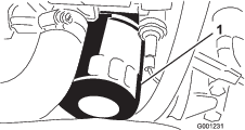
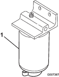
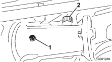
Servicing the Water Separator
| Maintenance Service Interval | Maintenance Procedure |
|---|---|
| Every 400 hours |
|
Drain the water or other contaminants from the water separator (Figure 49) daily.
-
Place a clean container under the fuel filter.
-
Loosen the drain plug on the bottom of the filter canister (Figure 49).
-
Clean the area where the filter canister mounts.
-
Remove the filter canister and clean the mounting surface.
-
Lubricate the gasket on the filter canister with clean oil.
-
Install the filter canister by hand until the gasket contacts mounting surface, then rotate it an additional 1/2 turn.
-
Tighten the drain plug on the bottom of the filter canister.
Cleaning the Fuel Tank
| Maintenance Service Interval | Maintenance Procedure |
|---|---|
| Every 400 hours |
|
Drain and clean tank if fuel system becomes contaminated or if you store the machine for an extended period. Use clean diesel fuel to flush out the tank.
Inspecting the Fuel Lines and Connections
| Maintenance Service Interval | Maintenance Procedure |
|---|---|
| Every 400 hours |
|
Inspect the fuel lines for deterioration, damage, or loose connections.
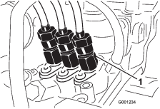
Purging the Air from the Fuel-Injector Tubing
Note: Perform this procedure only if you have purged air from the fuel system using the normal priming procedures and engine does not start; refer to Purging the Fuel-Injection Pump.
-
Loosen the tube nut at the No. 1 injector nozzle and holder assembly at the injection pump (Figure 50).
-
Move the throttle to the FAST position.
-
Rotate the key switch to the START position and watch the fuel flow around the tube nut.
-
Rotate the key switch to the OFF position when you attain a solid flow of fuel from the tube.
-
Tighten the tube nut securely.
-
Wipe clean any fuel that has accumulated around the injector nozzle and the injection pump.
-
Repeat steps 1 through 6 for the remaining nozzles.
Electrical System Maintenance
Electrical System Safety
Warning
Battery posts, terminals, and related accessories contain lead and lead compounds, chemicals known to the State of California to cause cancer and reproductive harm. Wash hands after handling.
-
Disconnect the battery before repairing the machine. Disconnect the negative terminal first and the positive last. Connect the positive terminal first and the negative last.
-
Charge the battery in an open, well-ventilated area, away from sparks and flames. Unplug the charger before connecting or disconnecting the battery.
-
Wear protective clothing and use insulated tools.
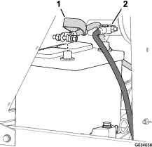
Servicing the Battery
Checking the Battery-Cable Connections
| Maintenance Service Interval | Maintenance Procedure |
|---|---|
| Every 50 hours |
|
Warning
Battery terminals or metal tools could short against metal machine components, causing sparks. Sparks can cause the battery gasses to explode, resulting in personal injury.
-
When removing or installing the battery, do not allow the battery terminals to touch any metal parts of the tractor.
-
Do not allow metal tools to short between the battery terminals and metal parts of the machine.
-
The battery cables must be tight on the terminals to provide good electrical contact.
-
If corrosion occurs, perform the following:
Warning
Incorrect battery cable routing could damage the machine and cables, causing sparks. Sparks can cause the battery gasses to explode, resulting in personal injury.
-
Always disconnect the negative (black) battery cable before disconnecting the positive (red) cable.
-
Always connect the positive (red) battery cable before connecting the negative (black) cable.
-
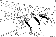
Open the hood; refer to Opening the Hood.
-
Disconnect the negative (-) cable from the battery post (Figure 51).
-
Slide the insulator cover away from the battery-cable clamp (Figure 51).
-
Disconnect the positive (+) cable from the battery post (Figure 51).
-
Scrape clean the clamps and terminals separately.
-
Coat the terminals of the battery cables with Grafo 112X (skin-over) grease ( Part No. 505-47) .
-
Connect the cables, positive (+) cable to the positive battery post (Figure 51).
-
Connect the negative (-) cable to the negative battery post (Figure 51).
-
Checking the Battery Electrolyte
| Maintenance Service Interval | Maintenance Procedure |
|---|---|
| Every 50 hours |
|
| Monthly |
|
Danger
Battery electrolyte contains sulfuric acid, which is lethal if consumed and causes severe burns.
-
Do not drink electrolyte and avoid contact with skin, eyes, or clothing. Wear eye protection to shield your eyes and rubber gloves to protect your hands.
-
Fill the battery where clean water is always available for flushing the skin.
Note: If you store the machine in a location where temperatures are extremely high, the battery will run down more rapidly than if you store the machine at a location where temperatures are cool.
-
Maintain the battery electrolyte concentration at a specific gravity between 1.265 to 1.299.
-
Maintain the cell level with distilled or demineralized water.
Note: Do not fill the cells above the bottom of the split ring inside each cell.
-
Clean the top of the battery periodically by performing the following:
Important: Do not remove the fill caps while cleaning the battery.
-
Washing the top of the battery with a brush dipped in ammonia or bicarbonate of soda solution.
-
Flush the top surface with clean water.
-
Accessing the Fuse Block and Standard Control Module
Removing the Control-Panel Plate
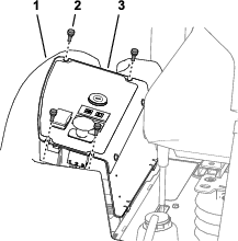
Installing the Control-Panel Plate
-
Connect the electrical connectors to the switches and warning lights that you disconnected in step 3 of Removing the Control-Panel Plate.
-
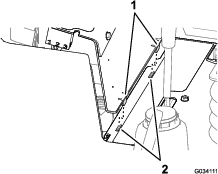
Align the 2 tabs at the bottom of the side panel with the 2 slots in the frame for the console (Figure 53).
-
Align the slots in the top of the control-panel plate with the holes in the flange of the fuel tank (Figure 52).
-
Assemble the control panel plate to the flange of the fuel tank with the 4 thumb screws (Figure 52) that you removed in step 1 of Removing the Control-Panel Plate.
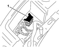
Accessing the Fuses
The fuse blocks and fuses are located under the control panel (Figure 54).
Standard Control Module (SCM)
Important: The information presented below is and overview of the standard control module. Refer to the Service Manual for the machine for troubleshooting procedures using the standard control module.
The standard control module (SCM) monitors and controls standard electrical features of the machine.
Yellow LED indicators on the printed-circuit board identify the inputs and outputs.
The SCM monitors inputs of the following:
-
Controls in the NEUTRAL position
-
Parking brake position
-
Power takeoff (PTO) operation
-
Engine starting function
-
High temperature condition
The SCM controls outputs features include the following:
-
The SCM energizes the outputs for the PTO, starter, and the ETR (energize to run) solenoids.
-
Output LEDs monitor relay condition indicating the presence of voltage at 1 of 3 specific output terminals.
Note: The SCM does not connect to an external computer or hand held device, it is not programmable, and it does not record intermittent fault troubleshooting data.
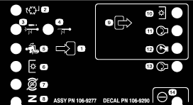
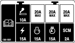
The Standard Control Module Decal
The decal on the SCM only includes symbols. The output box shows the 3 LED output symbols. All other LEDs are inputs. To identify the conditions the symbols indicate, refer to the chart in Standard Control Module Chart.
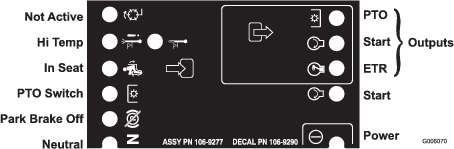
Standard Control Module Chart
Each row in the logic chart below identifies input and output requirements for each specific product function. The left column lists the product functions. The symbols identify specific circuit conditions, including energized to voltage, closed to ground, and open to ground.
| Inputs | Outputs | ||||||||||
|---|---|---|---|---|---|---|---|---|---|---|---|
| Function | Power On | In Neutral | Start On | Brake On | PTO On | In Seat | Hi Temp Shutdown | Hi Temp Warning | Start | ETR | PTO |
| Start | — | — | + | ⊗ | ⊗ | — | ⊗ | ⊗ | + | + | ⊗ |
| Run (Off Unit) | — | — | ⊗ | ⊗ | ⊗ | ⊗ | ⊗ | ⊗ | ⊗ | + | ⊗ |
| Run (On Unit) | — | ⊗ | ⊗ | — | ⊗ | — | ⊗ | ⊗ | ⊗ | + | ⊗ |
| Mow | — | ⊗ | ⊗ | — | — | — | ⊗ | ⊗ | ⊗ | + | + |
| Hi Temp Warning | — | ⊗ | ⊗ | — (A) | + | + | ⊗ | ||||
| Hi Temp Shutdown | — | ⊗ | — | ⊗ | ⊗ | ⊗ | |||||
|
(-) Indicates a circuit closed to ground. ( LED ON) (⊗) Indicates a circuit open to ground or de-energized (LED OFF) (+) Indicates an energized circuit (clutch coil, solenoid, or start input) (LED ON) A Blank indicates a circuit that is not involved with the logic. (A) Re-initiate the PTO input after engine cool down (cycle key on-off) |
|||||||||||
Servicing the Wire Harness
Prevent corrosion of wiring terminals by applying Grafo 112X (Skin-over) grease, Toro Part No. 505-47, to the inside of all harness connectors whenever you replace the harness.
Important: Whenever working with the electrical system, always disconnect the battery cables, negative (-) cable first, to prevent possible wiring damage from short-outs.
Drive System Maintenance
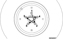
Torquing the Wheel-Lug Nuts
| Maintenance Service Interval | Maintenance Procedure |
|---|---|
| After the first hour |
|
| After the first 10 hours |
|
| Every 200 hours |
|
Wheel-lug nut torque specification: 102 to 108 N∙m (75 to 80 ft-lb)
Torque the lug nuts at the front and rear wheels in a crossing pattern as shown in Figure 56 to the specified torque.
Maintaining the Rear Axle
4-Wheel Drive Machines Only
Rear Axle-Lubricant Specification: SAE 80W-90 weight gear lube
Checking the Rear Axle Lubricant
4-Wheel Drive Machines Only
| Maintenance Service Interval | Maintenance Procedure |
|---|---|
| Every 200 hours |
|
The rear axle has 3 separate reservoirs that use SAE 80W-90 weight gear lube. Although the factory ships the axle with lubricant, check the lubricant level before operating the machine for the first time.
-
Position the machine on a level surface.
-
Remove the check plug from the center-axle housing and the axle and fill/check plugs at each outboard-axle case (Figure 57 and Figure 58).
-
Check that there is lubricant up to the threads at the bottom of each plug hole (Figure 57 and Figure 58).
-
If the level of lubricant is low, perform the following: and
-
If filling the center-axle housing, remove the fill plug (Figure 57).
-
Add the specified rear-axle lubricant into the axle reservoir(s) until the lubricant level up to the bottom of the check-plug holes (Figure 57 and Figure 58).
-
If removed from the center-axle housing, apply PTFE thread sealant to the threads of the fill plug and install it into the housing (Figure 57).
-
-
Apply PTFE thread sealant to the threads of the check plug from the center-axle housing and fill/check plugs from the 2 outboard-axle cases (Figure 57).
-
Install the check plug into the center-axle housing and fill/check plugs into the 2 outboard-axle cases (Figure 57 and Figure 58).
Changing the Rear Axle Lubricant
4-Wheel Drive Machines Only
| Maintenance Service Interval | Maintenance Procedure |
|---|---|
| Every 400 hours |
|
-
Position the machine on a level surface.
-
Clean the areas around the 3 drain plugs (Figure 59).
Note: 1 plug at each outboard-axle case and 1 plug at the center-axle housing.
-
Align a drain pan under the drain plug, remove the plug, and allow the oil to completely drain.
-
Apply PTFE thread sealant to the threads of the drain-plug and install it in the axle.
-
Repeat steps 3 and 4 at the other 2 drain plugs.
-
Remove the check plug from the center-axle housing and the fill/check plugs at each outboard-axle case.
-
Add the specified rear-axle lubricant into the axle reservoir(s) until the lubricant level up to the bottom of the threads at check-plug hole; refer to the lubrication specification in Maintaining the Rear Axle.
-
Apply PTFE thread sealant to the threads of the check plug from the center-axle housing and fill/check plugs from the 2 outboard-axle cases; refer to Figure 57 and Figure 58 in Checking the Rear Axle Lubricant.
-
Install the check plug into the center-axle housing and fill/check plugs into the 2 outboard-axle cases; refer to Figure 57 and Figure 58 in Checking the Rear Axle Lubricant.
Maintaining the Bidirectional Clutch
Clutch lubricant specification: Mobilfluid 424™
Important: Do not use engine oil (such as 10W30) in the bidirectional clutch. Anti-wear and extreme pressure additives cause undesirable clutch performance.
Note: Determine the left and right sides of the machine from the normal operating position.
Checking the Bidirectional Clutch Lubricant
4-Wheel Drive Machines Only
| Maintenance Service Interval | Maintenance Procedure |
|---|---|
| Every 200 hours |
|
-
Position the machine on a level surface.
-
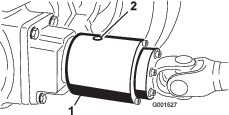
Rotate the clutch (Figure 60) to align the check plug at the 4 o'clock position.
-
Remove the check plug.
Note: The fluid level should be up to the hole in the clutch.
-
If the fluid level is low, add the specified fluid into the housing of the bidirectional clutch until it is 1/3 full.
-
Apply PTFE thread sealant to the threads of the check plug.
-
Install the check plug into the clutch housing.
Changing the Bidirectional-Clutch Lubricant
4-Wheel Drive Machines Only
| Maintenance Service Interval | Maintenance Procedure |
|---|---|
| Every 400 hours |
|
-
Position the machine on a level surface.
-
Clean the area around the check plug on the bidirectional clutch.
-
Rotate the clutch to align the check plug at the 6 o'clock position. (Figure 61).
-
Remove the check plug allowing all lubricant to flow into a drain pan.
-
Rotate the clutch to align the check-plug hole at the 4 o'clock position.
-
Add the specified fluid until the lubricant level is up to the threaded hole in the clutch housing.
Note: When filled correctly, the clutch housing is 1/3 full with clutch lubricant.
-
Apply PTFE thread sealant to the threads of the check plug.
-
Install the check plug into the clutch housing.
Maintaining the Rear Wheel Alignment
Checking the Rear Wheel Alignment
| Maintenance Service Interval | Maintenance Procedure |
|---|---|
| Every 200 hours |
|
-
Move the machine to a level surface, engage the parking brake, and remove the key from the key switch.
-
Rotate the steering wheel so that the rear wheels are straight ahead.
-
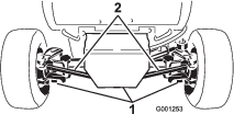
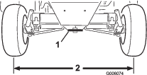
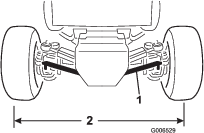
Measure the center-to-center distance at wheel hub height, in front and behind the rear tires.
Note: When aligned correctly, the rear wheels should not toe-in or toe-out.
-
If the wheels toe-in or toe-out, align the wheels by performing the following:
-
For 2-wheel drive machines, refer to Adjusting Rear Wheel Toe-in.
-
For 4-wheel drive machines, refer to Adjusting Rear Wheel Toe-in.
-
Adjusting Rear Wheel Toe-in
2-Wheel Drive Machines Only
-
Loosen the jam nuts at both ends of the left and right tie rods.
-
Adjust both tie rods until center-to-center distance at front and back of rear wheels is the same (Figure 62).
-
When rear wheels are adjusted correctly, tighten jam nuts against tie rods.
Adjusting Rear Wheel Toe-in
4-Wheel Drive Machines Only
-
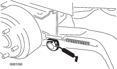
Remove cotter pin and castle nut securing 1 tie-rod ball joint to the mounting bracket on the axle and separate the ball joint from the axle (Figure 63).
-
Loosen the lock nut and bolt at the tie-rod clamp.
-
Rotate the tie-rod ball joint in or out until the center-to-center distance at front and back of the rear wheels is the same (Figure 63).
-
Install the ball joint to the mounting bracket and check the wheel toe-in.
-
After attaining the desired wheel alignment, assemble ball joint to the mounting bracket with the castle nut and cotter pin.
-
Tighten the locknut and bolt at the tie-rod clamp.
Torquing the Bolts for the Steering-Cylinder Mount
4-Wheel Drive Machines Only
| Maintenance Service Interval | Maintenance Procedure |
|---|---|
| Every 200 hours |
|
-
Move the machine to a level surface, shut off the engine and remove the key from the key switch.
-
Torque the 4 bolts for the steering-cylinder mount (Figure 64) to 65 to 81 N∙m (48 to 60 ft-lb).

Adjusting the Traction Drive
If the machine moves when the traction pedal is in the neutral position, adjust the traction cam.
Preparing to Adjust the Traction Drive
Lifting equipment and jack stand capacity: 1900 kg (2 ton) or greater
-
Move the machine to a level surface, shut off the engine, and engage the parking brake.
Warning
If the machine is not supported adequately, it may accidentally fall, injuring anyone under the machine.
Raise all 4 wheels off the ground or the machine may move while adjusting the traction drive for neutral.
-
Raise the machine and support it with 4 jack stands of the specified capacity under the frame.
-
Remove the seat and seat plate; refer to Removing the Seat and Seat Plate.
Adjusting the Traction Drive for Neutral
-
Locate the eccentric hex to the right of the hydraulic pump and below the control console (Figure 65).
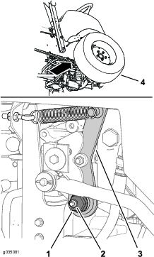
-
Loosen retaining nut until you can move the eccentric hex (Figure 65).
Note: Ensure that the retaining nut produces enough tension to keep the eccentric hex loosely seated in the neutral arm.
-
Start the engine. If the engine does not start, perform the following:
-
Locate the proximity sensor at the right, top side hydraulic pump (Figure 66).
-
Verify that the proximity sensor bracket is not bent, and that the light at the back of the sensor illuminates (Figure 66).
-
If the light at the proximity sensor is not illuminated, adjust the sensor position; refer to Adjusting the Proximity Sensor.
-
-
Rotate the eccentric hex counterclockwise until the front wheel starts to rotate forward, then rotate the hex eccentric clockwise until the front wheel starts to rotate rearward (Figure 65).
Warning
You must run the engine so that you can perform the final traction adjustment. Contact with hot or moving parts can result in personal injury.
Keep your hands, feet, face, and other body parts away from the muffler, other hot parts of the engine, and other rotating parts.
-
Determine the middle position of the neutral span and tighten the retaining nut.
Note: Perform this traction drive-neutral adjustment at low-speed idle and verify that the neutral adjustment is correct at high engine speed.
-
Tighten the nut securing the adjustment.
-
Shut off the engine.
Adjusting the Proximity Sensor
-
Locate the proximity sensor at the right, top side hydraulic pump (Figure 66).
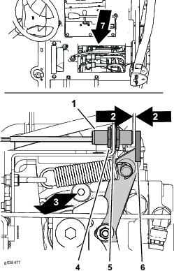
-
Loosen the jam nuts at either side of the sensor bracket (Figure 66).
-
Adjust jam nuts until there is a 2.5 to 3.6 mm(0.10 to 0.14 inch) gap between the end of the proximity sensor and the flange of the neutral arm (Figure 66).
-
Tighten the jam nuts (Figure 66).
Finishing the Traction Drive Adjustment
-
Remove the jack stands and lower the machine to the ground.
-
Install the seat and seat plate; refer to Installing the Seat and Seat Plate.
-
Test drive the machine to ensure that it does not move when the traction pedal is in neutral.
Adjusting the Steering Stops
4-Wheel Drive Machines Only
The rear-axle-steering stops help prevent over-travel of the steering cylinder in case of impact on the rear wheels. Adjust the stops so that there is 0.23 cm (0.090 inch) clearance between the bolt head and the knuckle on the axle when you turn the steering wheel completely to the left or to the right.
-
Thread the bolts in or out until you attain a clearance of 0.23 cm (0.090 inch); refer to Figure 67.
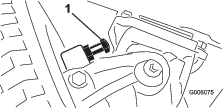
-
Loosen the screw on the tie-rod clamp.
-
Rotate the ball joint in or out to adjust the length of the tie rod.
-
Install the ball joint to the mounting bracket and check the wheel toe-in.
-
After attaining the desired adjustment, tighten the screw on the tie-rod clamp and secure the ball joint to the mounting bracket.
Cooling System Maintenance
Cooling System Safety
-
Swallowing engine coolant can cause poisoning; keep out of reach from children and pets.
-
Discharge of hot, pressurized coolant or touching a hot radiator and surrounding parts can cause severe burns.
-
Always allow the engine to cool at least 15 minutes before removing the radiator cap.
-
Use a rag when opening the radiator cap, and open the cap slowly to allow steam to escape.
-
-
Do not operate the machine without the covers in place.
-
Keep your fingers, hands, and clothing clear of rotating fan and drive belt.
-
Shut off the engine and remove the key before performing maintenance.
Coolant Specification
Cooling system capacity: 7.5 L (8 US qt)
Coolant-type specification:
| Recommended Coolant |
|
Note: Coolant must meet or exceed ASTM Standard 3306 |
| Glycol based pre-diluted coolant (50/50 blend) |
| or |
| Glycol based coolant mixed with distilled water (50/50 blend) |
| or |
| Glycol based coolant mixed with good quality water (50/50 blend) |
| CaCO3 + MgCO3 <170 ppm |
| Chloride <40 ppm (CI) |
| Sulfur <100 ppm (SO4) |
Checking the Cooling System and Coolant Level
| Maintenance Service Interval | Maintenance Procedure |
|---|---|
| Before each use or daily |
|
Warning
If the engine has been running, the radiator pressurizes and the coolant inside is hot. If you remove the cap, coolant may spray out, causing severe burns.
-
Do not remove the recovery-tank cap to check coolant levels.
-
Do not remove the recovery-tank cap when the engine is hot. Allow the engine to cool for at least 15 minutes or until the radiator cap is cool enough to touch without burning your hand.
-
Check the level of the coolant in the expansion tank (Figure 68).
Note: The coolant level should be between the marks on the side of the tank.
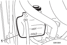
-
If the coolant is low, add the recommended replacement coolant as required. Do not use water only or alcohol-based coolants.Do not overfill.
-
Install the expansion-tank cap.
Checking the Hood Screen and Radiator for Debris
| Maintenance Service Interval | Maintenance Procedure |
|---|---|
| Before each use or daily |
|
To prevent the engine from overheating, keep the hood screen and radiator clean. Check the screen and radiator for buildup of grass, dust, and debris, and if necessary, clean any debris off these parts; refer to Checking the Hood Screen and Radiator for Debris.
Cleaning the Hood Screen and Radiator
| Maintenance Service Interval | Maintenance Procedure |
|---|---|
| Every 200 hours |
|
| Every 1,500 hours |
|
Note: If the PTO shuts off due to high engine temperature, first check the hood screen and radiator for an excessive buildup of debris. Clean the system before operating the machine. Do not shut off the engine immediately; allow the engine to cool by running it without a load.
Clean the radiator as follows:
-
Remove the hood.
-
Working from the fan side of the radiator, blow with low pressure, 172 kPa (25 psi), compressed air (do not use water). Repeat this step from the front of the radiator and again from the fan side.
-
After thoroughly cleaning the radiator, clean any debris that may have collected in the channel at the radiator base.
-
Clean the screen and install the hood onto the machine.
Brake Maintenance
Adjusting the Service Brakes
| Maintenance Service Interval | Maintenance Procedure |
|---|---|
| After the first 10 hours |
|
| After the first 50 hours |
|
| Every 50 hours |
|
Adjust the service brakes when there is more than 25 mm (1 inch) of free travel of the brake pedals or when the brakes do not work effectively. Free travel is the distance that the brake pedal moves before you feel braking resistance.
After the first 10 hours of operation, you should need to adjust the brakes only after considerable use thereafter. You can perform these periodic adjustments where the brake cable connects to the bottom of the brake pedals. When the cable is no longer adjustable, you can adjust the star nut on the inside of the brake drum to move the brake shoes outward. However, you will need to adjust the brake cables again to compensate for this adjustment.
-
Release the lock arm from the right-brake pedal so that both pedals operate independent of each other.
-
To reduce the free travel of the brake pedals, loosening the front jam nuts at the threaded end of the brake cable (Figure 69).
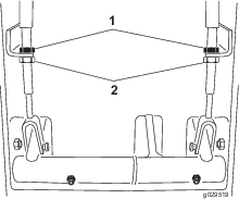
-
Rotate the rear jam nuts to move the cable rearward until the brake pedals have 13 mm to 25 mm (1/2 to 1 inch) of free travel.
-
When the free travel of the brake pedals is adjusted, tighten the front jam nuts.
Adjusting the Parking-Brake-Interlock Switch
-
Shut off the engine and remove the key from the key switch.
Note: Do not engage the parking brake.
-
Remove the knob from the parking-brake rod and the screws from the steering-tower cover (Figure 70).
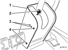
-
Slide the cover up the steering shaft to expose the parking brake switch (Figure 71).
-
Loosen the screws and nuts that secure the parking brake switch to the left side of the steering tower (Figure 70).
-
Align the paddle of the parking brake rod with the switch plunger (Figure 71).
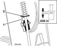
-
Press down on the parking-brake rod and push up the switch until the compressed length of the switch plunger is 0.7 mm (0.030 inches); refer to Figure 71.
Note: This is the distance between the brake-rod paddle and the switch-plunger housing.
-
Tighten the switch-mounting screws and nuts.
-
With the parking brake engaged, use a multimeter to measure continuity through the switch; when the position of the switch is correct, you should measure continuity through switch circuit.
Note: If there is no continuity, move the switch down slightly until there is continuity.
-
Check the operation of the parking brake interlock switch as follows:
-
Engage the parking brake.
-
Press the traction pedal while the engine is running and the PTO switch is in the OFF position; The parking brake interlock switch is operating correctly if the engine shuts off within 2 seconds.
Important: If the engine does not stop, the interlock system is not operating correctly. You must repair the interlock system before operating the machine.
-
-
Install the steering-tower cover and brake-rod knob.
Belt Maintenance
Checking the Condition of the Alternator Belt
| Maintenance Service Interval | Maintenance Procedure |
|---|---|
| Every 200 hours |
|
Check alternator belt for wear or damage.
Note: Replace the alternator belt if you find it worn or damaged.
Tensioning the Alternator Belt
| Maintenance Service Interval | Maintenance Procedure |
|---|---|
| After the first 10 hours |
|
| Every 200 hours |
|
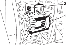
-
Apply 4.5 kg (10 lb) of force against the belt at a position midway between the pulleys.
-
If the belt deflects 10 mm (3/8 inch), the belt is properly tensioned.
-
If the belt deflects more than 10 mm (3/8 inch) or less than 10 mm (3/8 inch), proceed to step 2.
-
-
Loosen the mounting bolt for the alternator (Figure 72).
-
Increase or decrease the tension on the alternator belt and tighten the mounting bolt (Figure 72).
-
Repeat steps 1 through 3 until the belt tension is correct.
Servicing the PTO Belt
Checking the PTO Belt Tension
| Maintenance Service Interval | Maintenance Procedure |
|---|---|
| After the first 10 hours |
|
| After the first 50 hours |
|
| Every 200 hours |
|
-
Shut the engine off, engage the parking brake, and remove the key from the key switch.
-
Raise the engine hood and allow the engine to cool.
-
Loosen the tensioning-rod jam nut (Figure 73).
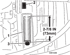
-
Use a 1/2-inch wrench to tighten or loosen the belt-tensioning spring (Figure 73). Adjust spring to a length of 73 mm (2-7/8 inch).
-
Tighten the jam nut.
Replacing the PTO Belt
-
Park the machine on a level surface, engage the parking brake, lower the cutting deck, shut off the engine, and remove the key from the key switch.
-
Raise the engine hood and allow the engine to cool.
-
Loosen the tensioning-rod jam nut (Figure 73).
-
Using a 1/2-inch wrench, loosen the belt-tensioning spring (Figure 73) all the way.
-
Rotate the PTO pulley toward the engine and remove the belt.
-
Install the new PTO belt and tension the pulley spring to 73 mm (2-7/8 inches) in length (Figure 73).
-
Tighten the jam nut (Figure 73) and close the hood.
Controls System Maintenance
Adjusting the PTO-Clutch Gap
| Maintenance Service Interval | Maintenance Procedure |
|---|---|
| Every 200 hours |
|
-
Shut off the engine, engage the parking brake, and remove the key from the switch.
-
Raise the engine hood and allow the engine to cool.
-
Adjust the air gap so that a 0.4 mm (0.015 inch) feeler gauge slides in between the clutch lining and friction plate with light pressure (Figure 74).
Note: You can decrease the gap by turning the adjusting nut clockwise (Figure 74). The maximum service gap is 0.7 mm (0.030 inch). Adjust all 3 air gaps.
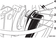
-
After the 3 air gaps are adjusted, check all 3 again.
Note: Adjusting 1 air gap can alter the other gaps.
Adjusting the Traction Pedal
Adjusting the Traction-Pedal Stop
You can adjust the traction pedal for operator comfort or to reduce the maximum forward speed of the machine.
-
Move the traction pedal fully forward (Figure 75).
Note: The traction pedal should contact the traction-pedal stop before the pump reaches full stroke.
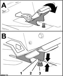
-
If the traction pedal does not contact the traction-pedal stop or if you want to reduce the forward speed of the machine, perform the following:
-
Hold the traction-pedal stop (Figure 75) with a wrench.
-
Loosen the jam nut at the bottom of the footrest plate (Figure 76).
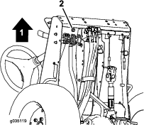
-
Move the traction pedal to the full forward position (Figure 75).
-
While holding the traction-pedal stop, adjust the jam nut that is above the footrest plate (Figure 75) until the traction pedal makes contact with the stop.
-
Lengthen the traction-pedal stop position by rotating the stop 1 full rotation counterclockwise away from the jam nut above the footrest plate.
Note: Shortening the traction-pedal-stop position will increase the forward speed of the machine.
-
While holding the traction-pedal stop, torque the jam nut at the bottom of the footrest plate (Figure 75 and Figure 76) to 37 to 45 N∙m (27 to 33 ft-lb).
-
Check that the traction pedal contacts the traction-pedal stop before the pump reaches full stroke.
Note: If the traction pedal does not contact the traction-pedal stop, repeat steps 1 through 7 or refer to Adjusting the Traction Rod.
-
Adjusting the Traction Rod
If traction pedal requires more adjustment, adjust the traction rod (Figure 77) as follows:
-
Remove the bolt and nut securing traction rod end to the pedal.
-
Loosen the jam nut that secures the rod end to the traction rod (Figure 77).
-
Rotate the rod until you achieve the desired length.
-
Tighten the jam nut (Figure 77) and secure the rod end to the traction pedal with the bolt and nut removed to lock the angle of the foot pedal.
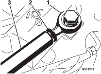
Hydraulic System Maintenance
Hydraulic System Safety
-
Seek immediate medical attention if fluid is injected into skin. Injected fluid must be surgically removed within a few hours by a doctor.
-
Ensure that all hydraulic-fluid hoses and lines are in good condition and all hydraulic connections and fittings are tight before applying pressure to the hydraulic system.
-
Keep your body and hands away from pinhole leaks or nozzles that eject high-pressure hydraulic fluid.
-
Use cardboard or paper to find hydraulic leaks.
-
Safely relieve all pressure in the hydraulic system before performing any work on the hydraulic system.
Hydraulic Fluid Specification
The machines reservoir is filled at the factory with high quality hydraulic fluid.
Hydraulic system capacity: 5.6 L (6.0 qt)
Hydraulic fluid-type specification:
| Toro Premium Transmission/Hydraulic Tractor Fluid (Available in 5 gallon pails or 55 gallon drums. See parts catalog or Toro distributor for part numbers.) |
Alternate fluids: If the Toro fluid is not available, you may use other petroleum-based Universal Tractor Hydraulic Fluids (UTHF) provided that its specifications fall within the listed range for all the following material properties and that it meets industry standards. We do not recommend the use of synthetic fluid. Consult with your lubricant distributor to identify a satisfactory product.
Note: Toro does not assume responsibility for damage caused by improper substitutions, so use products only from reputable manufacturers who will stand behind their recommendation.
| Material Properties: | |||
| Viscosity, ASTM D445 | cSt @ 40°C 55 to 62cSt @ 100°C 9.1 to 9.8 | ||
| Viscosity Index ASTM D2270 | 140 to 152 | ||
| Pour Point, ASTM D97 | -35°F to -46°F | ||
| Industry Specifications: | |||
| API GL-4, AGCO Powerfluid 821 XL, Ford New Holland FNHA-2-C-201.00, Kubota UDT, John Deere J20C, Vickers 35VQ25, and Volvo WB-101/BM | |||
Note: Many hydraulic fluids are almost colorless, making it difficult to spot leaks. A red dye additive for the hydraulic fluid is available in 20 ml (2/3 fl oz) bottles. A bottle is sufficient for 15 to 22 L (4 to 6 US gallons) of hydraulic fluid. Order Part No. 44-2500 from your authorized Toro distributor.
Servicing the Hydraulic System
Preparing to Service the Hydraulic System
-
Move machine to a level surface and engage the parking brake.
-
Place all controls in the NEUTRAL position and start the engine.
-
Run the engine at lowest possible engine speed to purge the system of air.
Important: Do not run the PTO.
-
Cycle steering wheel several times fully to the left and right, and align the steering wheels straight forward.
Checking the Hydraulic System and Fluid Level
| Maintenance Service Interval | Maintenance Procedure |
|---|---|
| Before each use or daily |
|
Note: The transaxle housing acts as the reservoir for the hydraulic system.
-
Raise the deck to extend the deck-lift cylinders, shut off the engine, and remove the key from the key switch.
-
Loosen dipstick cap (Figure 78) and remove the dipstick from transaxle filler tube and wipe the dipstick with a clean rag.
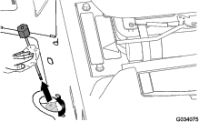
-
Insert the dipstick into the fill tube and thread dipstick cap onto the tube.
-
Remove the dipstick and check the fluid level (Figure 79).
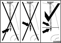
-
If the fluid level is below the lower mark of the dipstick, add the specified hydraulic fluid into the fill tube (Figure 80) until fluid level rises between the upper and lower marks when checked with the dipstick (Figure 79).
Important: Do not fill the transaxle housing with hydraulic fluid above the upper mark of the dipstick.
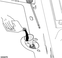
-
Thread the dipstick fill cap onto the filler tube.
Note: Do not tighten the cap with a wrench.
-
Check all hoses and fittings for leaks.
Changing the Hydraulic Fluid and Filter
| Maintenance Service Interval | Maintenance Procedure |
|---|---|
| After the first 10 hours |
|
| Every 200 hours |
|
| Every 1,500 hours |
|
Hydraulic fluid capacity: approximately 5.6 L (6 US qt)
-
Lower the deck to the shop floor, shut off the engine, and remove the key from the key switch.
-
Block the 2 rear wheels.
-
Jack up both sides of the front axle and support it with jack stands.
-
Replace the hydraulic filter (Figure 81).
Note: Drain pan capacity: a 5.6 L (6 US qt) capacity or greater.
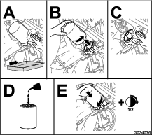
-
Remove jack stands and lower the machine.
-
Add the specified hydraulic fluid into the fill tube (Figure 80) until the fluid level in the transaxle housing (reservoir) shows at the midpoint between the upper and lower marks of the dipstick (Figure 79 ).
Important: Do not fill the transaxle housing with hydraulic fluid above the upper mark of the dipstick.
-
Start the engine, cycle the steering wheel and deck-lift cylinders, and check for oil leaks. Allow the engine to run for about 5 minutes, then shut it off.
-
After 2 minutes, check the level of the hydraulic fluid; refer to Checking the Hydraulic System and Fluid Level.
Storage
Preparing the Machine
-
Park the machine on a level surface; engage the parking brake; shut off the engine; remove the key; and wait for all movement to stop before leaving the machine.
-
Thoroughly clean the machine, deck, and the engine, paying special attention to these areas:
-
Radiator and radiator screen
-
Underneath the deck
-
Under the deck belt covers
-
PTO shaft assembly
-
All grease fittings and pivot points
-
Remove the control panel and clean out inside of the control box
-
Beneath the seat plate and top of the transmission
-
-
Check and adjust the air pressure in the tires; refer to Checking the Air Pressure in the Tires.
-
Remove, sharpen, balance, and install the mower blades; refer to the Operator’s Manual for your mower deck.
-
Check for loose fasteners and tighten them as necessary.
-
Lubricate all grease fittings and apply oil to pivot points and the transmission bypass-valve pins. Wipe clean any excess lubricant.
-
Lightly sand and use touch-up paint on painted areas that are scratched, chipped, or rusted. Repair any dents in the metal body.
Preparing the Engine
-
Change the engine oil and oil filter; refer to Changing the Engine Oil and Filter.
-
Start the engine and run it at idle speed for 2 minutes.
-
Shut off the engine.
-
Drain the fuel from the fuel tank, fuel lines, pump, filter, and separator.
-
Flush the fuel tank with clean diesel fuel and connect all fuel lines.
-
Service the air-cleaner assembly; refer to Servicing the Air Cleaner.
-
Seal the air-cleaner inlet and the exhaust outlet with weatherproof masking tape.
-
Secure all fuel-system fittings.
-
Check the anti-freeze protection level of the cooling system and adjust the concentration of the coolant as needed for expected minimum temperature in your area.
-
Check that the oil-filler cap and fuel-tank cap are installed securely.
Storing the Battery
-
Service the battery and cables as follows:
-
Disconnect the negative terminal first and the positive last.
-
Clean the battery, terminals, and posts with a wire brush and baking-soda solution.
-
Coat the cable terminals and battery posts with Grafo 112X skin-over grease (Toro Part No. 505-47) to prevent corrosion.
-
If you plant to store the machine more than 30 days, remove the battery and charge it fully.
Note: Slowly charge the battery for 24 hours every 60 days to prevent lead sulfation of the battery.
Note: Charge the battery in an open, well-ventilated area, away from sparks and flames. Unplug the charger before connecting or disconnecting the battery. Wear protective clothing and use insulated tools.
-
-
Store the battery on the shelf on the machine.
-
Leave the cables disconnected if you store the battery in the machine.
-
Store the battery in a cool atmosphere to avoid quick deterioration of the charge in the battery.
-
To prevent the battery from freezing, fully charge it. The electrolyte specific gravity of a fully charged battery is between 1.265 to 1.299.