| Electromagnetic Compatibility |
| Domestic: This device complies with FCC Rules Part 15. Operation is subject to the following two conditions: (1) This device may not cause harmful interference and (2) this device must accept any interference that may be received, including interference that may cause undesirable operation. |
| This equipment generates and uses radio frequency energy and if not installed and used properly, in strict accordance with the manufacturer's instructions, may cause interference to radio and television reception. It has been type tested and found to comply within the limits of a FCC Class B computing device in accordance with the specifications in Subpart J of Part 15 of FCC Rules, as stated above. However, there is no guarantee that interference will not occur in a particular installation. If this equipment does cause interference to radio or television reception, which can be determined by turning the equipment off and on, the user is encouraged to try to correct the interference by one or more of the following measures:Reorient the receiving antenna, relocate the remote control receiver with respect to the radio/TV antenna or plug the controller into a different outlet so that the controller and radio/TV are on different branch circuits.If necessary, the user should consult the dealer or an experienced radio/television technician for additional suggestions.The user may find the following booklet prepared by the Federal Communications Commission helpful: "How to Identify and Resolve Radio-TV Interference Problems". This booklet is available from the U.S. Government Printing Office, Washington, DC 20402. Stock No. 004-000-00345-4. |
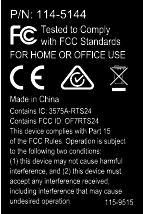
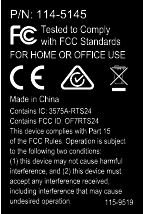
| FCC ID: OF7RTS24 |
| IC: 3575A-RTS24 |
| Operation is subject to the following two conditions: (1) this device may not cause interference, and (2) this device must accept any interference, including interference that may cause undesired operation of the device. |
Safety
Improperly using or maintaining this
system can result in injury. To reduce the potential for injury, comply
with these safety instructions and the safety instruction throughout
this document, denoted by the safety-alert symbol  , which means: Caution, Warning, or Danger—personal safety instruction. Failure to comply with the instruction
may result in personal injury or death.
Safety and Instructional Decals
 |
Safety decals and instructions are easily visible to the operator and are located near any area of potential danger. Replace any decal that is damaged or missing. |

Setup
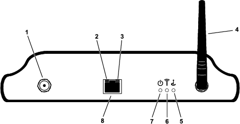
myTurf™ BaseStation Overview

Placing the myTurf™ BaseStation
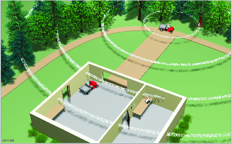
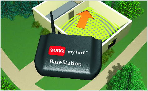
Choosing a suitable location for the BaseStation has the largest impact on wireless connectivity. You can determine a good location by examining your operating area and equipment movement patterns. Find a place that meets the following requirements:
-
The location should be in line-of-sight and within 76 m (250 ft) of an area heavily trafficked by machines.
-
The line-of-sight can be through an opening such as a door or window.
-
The location must be indoors and away from direct exposure to the elements.
-
The area should be clear of materials and items that would weaken the transmission of radio waves (i.e., concrete walls, microwaves, cordless phones). These items can block, absorb, and/or disrupt radio waves.
-
The location must have a high-speed Internet connection.
-
For system startup, ensure that the equipment with the new wireless hourmeter installed are within a 9 m (30 ft) radius of the BaseStation.
-
Refer to Figure 3 and Figure 4 for examples of BaseStation placement.
Note: In applications where the BaseStation cannot pick up the signal, a Repeater may be deployed using the same principles described previously.
Installing the myTurf™ BaseStation
Parts needed for this procedure:
| BaseStation | 1 |
| Whip antenna | 1 |
| Power adapter | 1 |
| Network cable | 1 |
-
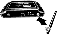
With the whip antenna pointed vertically, install the whip antenna to the BaseStation (Figure 5).
-
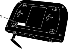
Find the device ID label on the bottom of the BaseStation and record the device ID from the label in the space provided on this document (Figure 6).
Note: This information is necessary for registration at myTurf.com.
-
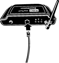
Connect one end of the ethernet cable to the BaseStation and the other to a dedicated Internet connection (Figure 7).
Do not plug the BaseStation into a PC.
A dedicated Internet connection can be defined as follows:
-
A standalone connection in the wall that is live to the Internet with a category 5 socket.
-
A separate “Line In” on a router or switch that is connected to the Internet.
Note: If there is only 1 Internet connection, you may need a router or a switch to allow multiple devices to connect to the Internet. Please consult your Internet-service provider for more information.
-
-
Remove the protective insert from the power adapter and install the plug appropriate for you region (Figure 8).
Plug the power adapter into a power strip, surge protector, or wall outlet. Toro recommends using a surge protector.

Powering the myTurf™ BaseStation
-
Plug the power cord into the BaseStation (Figure 9).
When the BaseStation has power and is connected to the Internet, the following occurs:
-
The BaseStation powers on.
-
The BaseStation validates the Internet connection.
-
Then, if connected to the Internet, the BaseStation contacts the myTurf™ servers and establishes a connection.
Note: It may take a few minutes to complete this process.
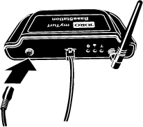
-
-
Ensure that the power light illuminates (Figure 10).
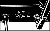
-
Ensure that the Internet connection light illuminates (Figure 11).
The connection LED light flickers and flashes steadily when functioning properly.
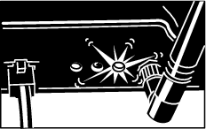
-
If the BaseStation connects to the Internet, ensure that the BaseStation contacts the myTurf servers and establishes a connection (Figure 12).
The connection indicator light will flicker and flash during the attempt. A connection is established when the connection light remains steadily illuminated.
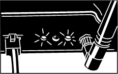
Installing the myTurf™ Wireless Hour Meter
Parts needed for this procedure:
| Wireless hour meter | 1 |
Important: The wireless hour meter has a 16 V DC maximum.
Install a wireless hour meter in place of an existing hour meter on each machine in the fleet. Hour meters are installed with varying styles of mounts and bezels. Take care when removing the existing hour meter to retain all the fasteners and bezels.
In most cases, hour meters are installed on dashboards for ease of reading, but some machines have them installed elsewhere. If you cannot find the hour meter, consult the Operator’s Manual or log on to www.Toro.com for help locating it.
-
On the new wireless hour meter, record the device ID from the label and machine model and serial number in the space provided on this document.
Note: This information is necessary for registration at myTurf.com.
-
Record the hours listed on the existing hour meter in the space provided.
-
Remove the existing hour meter from its mounting frame and disconnect it from the wire harness.
-
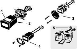
Install the new wireless hour meter into the same position.
There are optional configurations, so the choose the configuration that applies to your application (Figure 13).
Installing the myTurf™ Wireless Hour Meter
Parts needed for this procedure:
| Wireless hour meter | 1 |
| Cable tie | 1 |
-
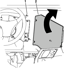
Remove the 3 button-head screws and rotate the control panel out to the right (Figure 14).
-
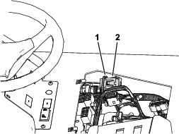
Connect the end of the wireless hour meter assembly to the portion of the dash wire harness labeled HR-METER found to the left of the control panel opening (Figure 15).
-
Secure the wireless hour meter to the wire harness using the cable tie (Figure 15).
-
Close the control panel and secure it using the previously removed 3 button-head screws.
Adding Wireless Equipment to myTurf™
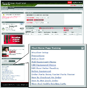
Log into myTurf.toro.com. Enter your user name and password to access your account. Select the myTurf™ Wireless tab to complete the registration process.
Use the training modules on myTurf™ to learn how to register the BaseStation, Repeater (if needed), and wireless hour meters.
Note: In applications where the BaseStation cannot pick up the signal, a Repeater may be deployed using the same principles described here.
| Device Type | Device ID | Machine Model No. | Machine Serial No. | Existing Hour Meter Reading |
| Example: BaseStation | 4293918689 | N/A | N/A | N/A |
| Example: Wireless Hourmeter | 18 | 41778 | 260000301 | 551 |