
 , which means
Caution, Warning, or Danger—personal safety instruction. Failure
to comply with these instructions may result in personal injury or
death.
, which means
Caution, Warning, or Danger—personal safety instruction. Failure
to comply with these instructions may result in personal injury or
death.

Maintenance
Note: Download a free copy of the electrical or hydraulic schematic by visiting www.Toro.com and searching for your machine from the Manuals link on the home page.
Maintenance Safety
-
Before you leave the operator’s position, do the following:
-
Park the machine on a level surface.
-
Move the throttle lever to the idle position.
-
Ensure that the motion pedals are in neutral position.
-
Engage the parking brake.
-
Shut off the engine.
-
Wait for all moving parts to stop.
-
Allow the machine to cool before adjusting, servicing, or cleaning.
-
-
If possible, do not perform maintenance while the engine is running. Keep away from moving parts.
-
Use jack stands to support the machine or components when required.
-
Carefully release pressure from components with stored energy.
Recommended Maintenance Schedule(s)
| Maintenance Service Interval | Maintenance Procedure |
|---|---|
| After the first 5 hours |
|
| After the first 20 hours |
|
| Before each use or daily |
|
| After each use |
|
| Every 50 hours |
|
| Every 100 hours |
|
| Every 300 hours |
|
| Every 400 hours |
|
Important: Refer to your engine owner's manual for additional maintenance procedures.
Notation for Areas of Concern
| Inspection performed by: | ||
| Item | Date | Information |
| 1 | ||
| 2 | ||
| 3 | ||
| 4 | ||
| 5 | ||
| 6 | ||
| 7 | ||
| 8 | ||
Pre-Maintenance Procedures
Do not tilt the machine unless it is necessary. If you tilt the machine, engine oil could enter the cylinder head of the engine, and hydraulic fluid could leak from the cap located on top of the tank. These leaks may result in expensive repairs to the machine. To perform service under the deck, lift the machine with a hoist or a small crane.
Preparing for Maintenance
-
Drive or transport the machine to a level surface; refer to Transporting the Machine.
-
If lowered, raise the transport wheels; refer to Raising the Machine onto the Transport Wheels.
-
If the engine is running, shut off the engine.
-
Engage the parking brake.
-
If the engine is hot, wait for the engine and hydraulic system to cool.
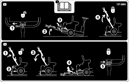
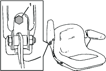
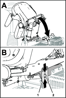
Raising the Operator’s Seat
Lowering the Operator’s Seat
Tilt the seat down until the seat latch snaps securely over the seat-latch pin (Figure 24).
Lubrication
Lubricating the Drive-Roller Bearing
| Maintenance Service Interval | Maintenance Procedure |
|---|---|
| Before each use or daily |
|
Grease Type: No. 2 lithium grease
-
Prepare the machine for maintenance; refer to Preparing for Maintenance.
-
Wipe the area clean so that foreign matter cannot be forced into the bearing.
-
Pump grease into the grease fitting as shown in Figure 25.
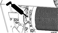
-
Wipe up any excess grease.
Important: After greasing, run the machine off the turf somewhere briefly to disperse any excess lubricant, to avoid damaging the turf.
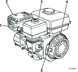
Engine Maintenance
Engine Safety
-
Shut off the engine before checking the oil or adding oil to the crankcase.
-
Do not change the governor speed or overspeed the engine.
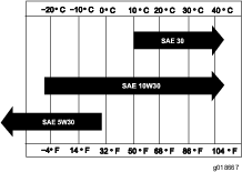
Engine Oil Specification
Type: APl service classification SL or higher
Viscosity: select the oil viscosity according to ambient temperature; refer to Figure 26.
Checking the Engine-Oil Level
| Maintenance Service Interval | Maintenance Procedure |
|---|---|
| Before each use or daily |
|
Note: The best time to check the engine oil is when the engine is cool before it has been started for the day. If it has already been run, allow the oil to drain back down to the sump for at least 10 minutes before checking it.
-
Prepare the machine for maintenance; refer to Preparing for Maintenance.
-
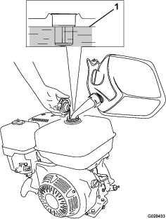
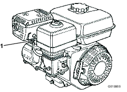
Clean the area around the oil-filler cap (Figure 27).
-
Remove the oil-filler cap by rotating it counterclockwise.
-
Check the oil level (Figure 28).
The engine is full of oil when the oil level is at the bottom edge of the oil-fill port.
Note: If the oil level is below the bottom edge of the oil-fill port, add enough of the specified oil to raise level to the bottom edge of the oil-fill port.
Important: Do not overfill the crankcase with engine oil.
-
Install the oil-filler cap and wipe up any spilled oil.
Changing the Engine Oil
| Maintenance Service Interval | Maintenance Procedure |
|---|---|
| After the first 20 hours |
|
| Every 100 hours |
|
Preparing the Machine
-
Start the engine and run it for a few minutes to warm the engine oil; then shut off the engine.
-
Raise the machine onto the transport wheels; refer to Raising the Machine onto the Transport Wheels.
-
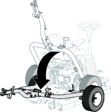
Tilt the machine so that the end of the machine with the engine is closer to the ground, and support the other end of the machine to hold it in this position.
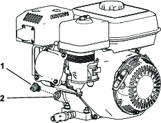
Draining the Engine Oil
-
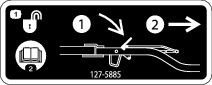
Install the drain hose onto the drain valve (Figure 29).
-
Place the other end of the hose (Figure 29) into a drain pan with a 1 L (1 US qt).
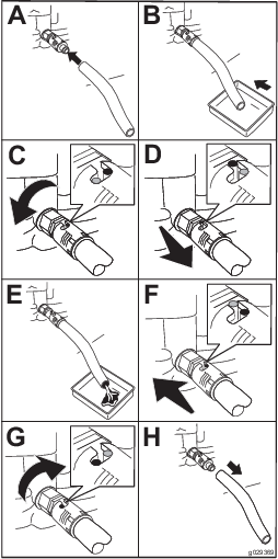
-
Turn the oil drain valve 1/4 turn counterclockwise and allow the engine oil to drain completely (Figure 29).
-
Turn the oil drain valve 1/4 turn clockwise to close the valve (Figure 29).
-
Remove the drain hose (Figure 29) and wipe any spilled oil.
-
Dispose of the waste oil properly.
Note: Recycle it according to local codes.
Adding Oil to the Engine
Crankcase Capacity: 0.60 L (0.63 US qt)
-
Lower the machine onto the rollers; refer to Lower the Machine onto the Rollers.
-
Fill the crankcase with the specified oil; refer to Engine Oil Specification and Checking the Engine-Oil Level.
Checking the Air-Filter Elements
| Maintenance Service Interval | Maintenance Procedure |
|---|---|
| Before each use or daily |
|
-
Prepare the machine for maintenance; refer to Preparing for Maintenance.
-
Remove the wing nut securing the air-cleaner cover to the air cleaner, and remove the cover (Figure 30).
-
Clean the air-cleaner cover thoroughly.
-
Check the foam air-filter element for dirt and debris.
Clean the foam air-filter if needed; refer to Cleaning the Foam Air-Filter Element.
-
Assemble the air-cleaner cover to the air cleaner with the wing nut (Figure 30).
Servicing the Air Cleaner
| Maintenance Service Interval | Maintenance Procedure |
|---|---|
| Before each use or daily |
|
| Every 50 hours |
|
| Every 300 hours |
|
Cleaning the Foam Air-Filter Element
-
Remove the wing nut securing the air-cleaner cover to the air cleaner, and remove the cover (Figure 30).
-
Remove the wing nut from the air filter, and remove the filter (Figure 30).
-
Remove the foam air-filter element from the paper element (Figure 30).
If the paper air-filter element is dirty or damaged, clean it or replace it; refer to Cleaning the Paper Air-Filter Element.
-
Wash the foam air-filter element in a solution of liquid soap and warm water.
-
Squeeze the foam element to remove the dirt.
Important: Do not twist the element, because the foam may tear.
-
Dry the foam element by wrapping it in a clean rag.
-
Squeeze the rag and foam element to dry the element.
Important: Do not twist it, because the foam may tear.
-
Saturate the foam element with clean engine oil.
-
Squeeze the element to remove excess oil and to distribute the oil thoroughly.
Note: The foam element should be damp with oil.
Cleaning the Paper Air-Filter Element
Clean the paper element by tapping the filter element several times on a hard surface to remove the dirt.
Important: Never brush dirt off the element or use compressed air to remove dirt; brushing forces dirt into the fibers, and compressed air will damage the paper filter.
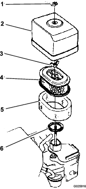
Assembling the Air Filter Elements
-
Assemble the foam air-filter element onto the paper element (Figure 30).
-
Inspect the gasket for wear and damage (Figure 30).
Replace the gasket if it is worn or damaged.
-
Ensure that the gasket is positioned on the air inlet for the carburetor (Figure 30).
-
Assemble the air-filter elements to carburetor with the wing nut (Figure 30).
-
Assemble the air-cleaner cover to carburetor with the other wing nut (Figure 30).
Servicing the Spark Plug
| Maintenance Service Interval | Maintenance Procedure |
|---|---|
| Every 100 hours |
|
| Every 300 hours |
|
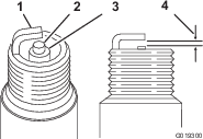
Type: NGK BPR6ES spark plug or equivalent
Air Gap: 0.70 to 0.80 mm (0.028 to 0.031 inch); refer to Figure 32
-
Prepare the machine for maintenance; refer to Preparing for Maintenance.
-
Disconnect the spark-plug wire from the spark plug (Figure 31).
-
Clean around the spark plug, and remove the plug from the cylinder head.
Important: Replace a cracked, fouled, or dirty spark plug. Do not sand blast, scrape, or clean the electrodes, because engine damage could result from grit entering the cylinder.
-
Set the air gap to 0.70 to 0.80 mm (0.028 to 0.031 inch) as shown in Figure 32).
-
Install the correctly gapped spark plug carefully by hand to avoid cross-threading.
-
After the spark plug is seated, tighten it with a spark-plug wrench as follows:
-
When installing a new spark plug, tighten it 1/2 turn after the spark plug seats, to compress the gasket.
-
When installing the original spark plug, tighten it 1/8 to 1/4 turn after the spark plug seats, to compress the gasket.
Important: A loose spark plug can overheat and damage the engine. Overtightening the spark plug can damage the threads in the cylinder head.
-
-
Connect the spark-plug wire to the spark plug.
Checking and Adjusting the Valve Clearance
| Maintenance Service Interval | Maintenance Procedure |
|---|---|
| Every 300 hours |
|
Important: Refer to your authorized Toro distributor for service.
Fuel System Maintenance
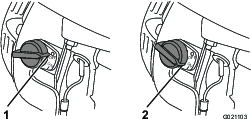
Cleaning the Sediment Cup
| Maintenance Service Interval | Maintenance Procedure |
|---|---|
| Every 100 hours |
|
-
Prepare the machine for maintenance; refer to Preparing for Maintenance.
-
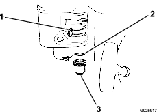
Move the fuel-shutoff valve to the OFF position (Figure 33).
-
Remove the fuel sediment cup and O-ring (Figure 33).
-
Check the O-ring for wear and damage; replace the O-ring if it is worn or damaged.
-
Wash the sediment cup and O-ring in nonflammable solvent, and dry them thoroughly.
-
Place the O-ring in the fuel-shutoff valve and install the sediment cup (Figure 33). Tighten the sediment cup securely.
Electrical System Maintenance
Checking the Safety-Interlock System
| Maintenance Service Interval | Maintenance Procedure |
|---|---|
| Before each use or daily |
|
Caution
If the safety-interlock switches are disconnected or damaged, the machine could operate unexpectedly, causing personal injury.
-
Do not tamper with the interlock switches.
-
Check the operation of the interlock switches daily, and replace any damaged switches before operating the machine.
Important: If the safety-interlock system does not operate as described below, have an authorized Toro distributor repair it immediately.
-
If on the transport wheels, lower the machine onto the rollers; refer to Lower the Machine onto the Rollers.
-
Engage the parking brake, ensure that the motion pedals are in the NEUTRAL position, and start the engine.
-
Sit on the seat.
-
With the parking brake engaged, gently press a motion pedal down; the engine should shut off after approximately 1 second.
-
With the engine running and the brake disengaged, stand up and verify that the engine shuts off after 1 second.
Note: The safety-interlock system is also designed to shut off the engine if the operator rises off the seat while the machine is moving.
Brake Maintenance
Checking the Parking Brake
| Maintenance Service Interval | Maintenance Procedure |
|---|---|
| Before each use or daily |
|
-
Drive or transport the machine to a level surface.
-
If you transport the machine, disconnect it from the tow vehicle and lower the machine onto the rollers; refer to Disconnecting the Machine from the Tow Vehicle and Lower the Machine onto the Rollers.
-
Engage the parking brake.
-
Start the engine and set the engine speed to IDLE.
-
Sit on the operator’s seat.
-
Press one of the motion pedals.
Important: The machine should not move. If it moves, adjust the parking brake; refer to Adjusting the Parking Brake.
Note: The engine shuts off in 1 second when you press the motion pedal with the parking brake engaged.
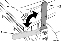
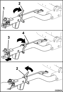
Adjusting the Parking Brake
-
Ensure that the engine is shut off.
-
Release the parking brake.
-
Adjust the parking brake as follows:
-
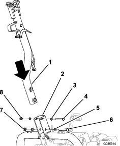
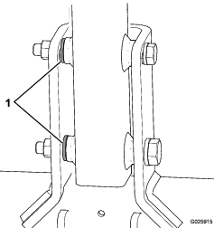
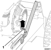
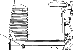
To increase the brake force, rotate the brake locknut clockwise (Figure 34).
-
To decrease the brake force, rotate the brake locknut counterclockwise (Figure 34).
-
-
Check the parking brake; refer to Checking the Parking Brake.
-
Start the engine and set the engine speed to IDLE.
-
Sit in the operator’s seat.
-
Release the parking brake.
-
Press one of the motion pedals.
The machine should move. If the machine does not move with the parking brake released, repeat steps 3 through 8 until the machine does not move when the barking brake is engaged and the machine moves when the parking brake is released.
-
Engage the parking brake and shut off the engine.
Hydraulic System Maintenance
Hydraulic System Safety
-
Seek immediate medical attention if fluid is injected into skin. Injected fluid must be surgically removed within a few hours by a doctor.
-
Ensure that all hydraulic-fluid hoses and lines are in good condition and all hydraulic connections and fittings are tight before applying pressure to the hydraulic system.
-
Keep your body and hands away from pinhole leaks or nozzles that eject high-pressure hydraulic fluid.
-
Use cardboard or paper to find hydraulic leaks.
-
Safely relieve all pressure in the hydraulic system before performing any work on the hydraulic system.
Checking the Hydraulic Hoses and Fittings
| Maintenance Service Interval | Maintenance Procedure |
|---|---|
| Before each use or daily |
|
Check the hydraulic system for leaks, loose mounting supports, wear, loose fittings, weather deterioration, and chemical deterioration. Make all necessary repairs before operating the machine.
Warning
Hydraulic fluid escaping under pressure can penetrate skin and cause injury.
-
Seek immediate medical attention if fluid is injected into skin.
-
Make sure that all hydraulic fluid hoses and lines are in good condition and all hydraulic connections and fittings are tight before applying pressure to the hydraulic system.
-
Keep your body and hands away from pinhole leaks or nozzles that eject high-pressure hydraulic fluid.
-
Use cardboard or paper to find hydraulic leaks.
-
Safely relieve all pressure in the hydraulic system before performing any work on the hydraulic system.
Hydraulic Fluid Specification
Recommended Hydraulic Fluid: Toro Premium All Season Hydraulic Fluid (Available in 5 US gallon pails or 55 US gallon drums. Refer to the Parts Catalog or contact your authorized Toro distributor for part numbers.
Alternative fluids: If the Toro fluid is not available, other conventional, petroleum-based fluids may be used, provided they meet all the following material properties and industry specifications. Check with your oil supplier to see whether the oil meets these specifications.
Note: Toro will not assume responsibility for damage caused by improper substitutions, so use only products from reputable manufacturers who will stand behind their recommendation.
| High Viscosity Index/Low Pour Point Anti-wear Hydraulic Fluid, ISO VG 46 Multigrade | |
| Material Properties: | |
| Viscosity, ASTM D445 | cSt @ 40°C (104°F) 44 to 48cSt @ 100°C (212°F) 7.9 to 9.1 |
| Viscosity Index ASTM D2270 | 140 or higher |
| Pour Point, ASTM D97 | -37°C to -45°C (-34°F to -49°F) |
| FZG, Fail stage | 11 or better |
| Water content (new fluid): | 500 ppm (maximum) |
| Industry Specifications: | |
| Vickers I-286-S, Vickers M-2950-S, Denison HF-0, Vickers 35 VQ 25 (Eaton ATS373-C) | |
The proper hydraulic fluids must be specified for mobile machinery (as opposed to industrial plant usage), multiweight-type, with ZnDTP or ZDDP anti-wear additive package (not an ashless-type fluid).
Note: Many hydraulic fluids are almost colorless, making it difficult to spot leaks. A red dye additive for the hydraulic system fluid is available in 20 ml (2/3 fl oz) bottles. One bottle is enough for 15 to 22 L (4 to 6 US gallons) of hydraulic fluid. Order Part No. 44-2500 from your authorized Toro distributor.
Checking the Hydraulic-Fluid Level
| Maintenance Service Interval | Maintenance Procedure |
|---|---|
| Before each use or daily |
|
Note: Before working on any part of the hydraulic drive system, shut off the engine to depressurize the system. Before starting the engine after hydraulic system maintenance, and pressurizing the hydraulic lines, check all hoses and connectors for damage and to ensure that they are tight. Replace any damaged hoses and tighten any loose couplings as required.
-
Prepare the machine for maintenance; refer to Preparing for Maintenance.
-
Raise the operator’s seat; refer to Raising the Operator’s Seat.
-
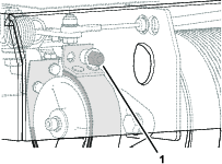
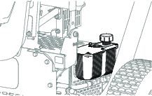
Remove the cap and check hydraulic-fluid level in the reservoir (Figure 35).
The hydraulic-fluid level should cover the word COLD that is embossed into the baffle of the reservoir.
-
If necessary, add the specified hydraulic fluid to the reservoir until the fluid covers the cold-fluid level on the baffle.
Note: The baffle in the reservoir is labeled HOT and COLD. Fill the reservoir to the appropriate level depending upon the temperature of the fluid. The fluid level varies with the temperature of the fluid. The cold level shows the level of the fluid when it is at 24°C (75°F). The hot level shows the level of fluid when it is at 107°C (225°F).For example: If the fluid is at ambient-air temperature, about 24°C (75° F), fill only to the cold level. If the fluid is about 65°C (150° F), fill to halfway between the hot and cold levels.
-
Replace the hydraulic reservoir cap and tighten it until it is snug.
Important: Do not overtighten the reservoir cap.
-
Wipe up any spilled fluid.
-
Lower the operator’s seat; refer to Lowering the Operator’s Seat.
Changing the Hydraulic Fluid and Filter
| Maintenance Service Interval | Maintenance Procedure |
|---|---|
| After the first 20 hours |
|
| Every 400 hours |
|
Important: Use only the specified hydraulic fluid. Other fluids could cause system damage.
Preparing to Change the Hydraulic Fluid and Filter
-
Drive or transport the machine to a level surface; refer to Transporting the Machine.
-
If you run the engine, shut off the engine.
-
Engage the parking brake.
-
If the machine is on the rollers, raise it onto the transport wheels; refer to Raising the Machine onto the Transport Wheels.
-
Raise the operator’s seat; refer to Raising the Operator’s Seat.
-
If you run the engine, wait for the engine and hydraulic system to cool.
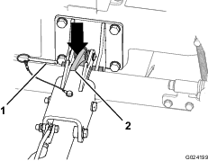
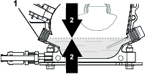
Draining the Hydraulic Fluid
-
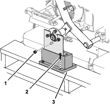
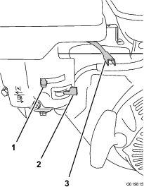
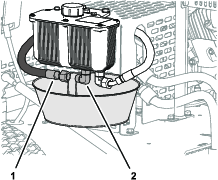
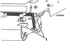
Align a drain pan with a 2 L (2 US qt) capacity under the hydraulic reservoir (Figure 36).
-
Remove the hydraulic-supply hose from the fitting of the reservoir, and allow the hydraulic fluid to drain completely (Figure 36).
-
Install the hydraulic hose that you removed in step 2.
-
Wipe up any spilled hydraulic fluid.
-
Dispose of the waste hydraulic fluid according to local codes.
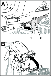
Changing the Filter
| Maintenance Service Interval | Maintenance Procedure |
|---|---|
| After the first 20 hours |
|
| Every 400 hours |
|
-
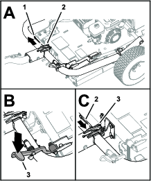
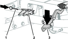
Clean the area around the filter head and hydraulic filter.
-
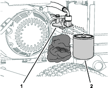
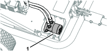
Pack rags under the hydraulic filter (Figure 37).
-
Carefully remove the hydraulic filter (Figure 37).
-
Fill the replacement filter with the specified hydraulic fluid and lubricate the sealing gasket with hydraulic fluid.
-
Install the filter onto the filter head by hand (Figure 37) until the gasket contacts the filter head, then tighten the filter 3/4 turn further.
-
Wipe up any spilled hydraulic fluid.
-
Dispose of the old filter according to local codes.
Filling the Hydraulic Reservoir
-
Lower the machine onto the rollers; refer to Lower the Machine onto the Rollers.
-
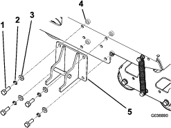
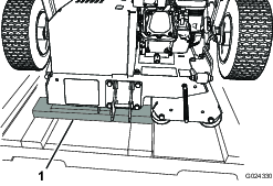
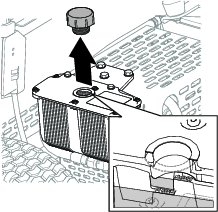
Remove the hydraulic-reservoir cap (Figure 38).
-
Fill the reservoir with the specified hydraulic fluid; refer to Hydraulic Fluid Specification and Checking the Hydraulic-Fluid Level.
-
Install the reservoir cap (Figure 38).
-
Wipe up any spilled hydraulic fluid.
-
Start the engine and run it at low idle for 3 to 5 minutes.
Running the engine circulates the hydraulic fluid and removes air trapped in the hydraulic system.
-
Check the machine for hydraulic leaks at the reservoir, hydraulic hoses, and the hydraulic filter.
Repair all hydraulic leaks.
-
Shut off the engine, check the hydraulic-fluid level, and add fluid if necessary.
-
Lower the operator’s seat; refer to Lowering the Operator’s Seat.
Chassis Maintenance
Checking the Tire Air Pressure
| Maintenance Service Interval | Maintenance Procedure |
|---|---|
| Before each use or daily |
|
-
Measure the air pressure in the tires of the transport wheels.
You should measure 103 kPa (15 psi).
-
If the tire air pressure is higher than or lower than 103 kPa (15 psi), add air to or remove air from the tires until you measure 103 kPa (15 psi).
Checking the Machine for Loose Hardware
| Maintenance Service Interval | Maintenance Procedure |
|---|---|
| After the first 5 hours |
|
| Before each use or daily |
|
Check the chassis for any loose or missing nuts and bolts.
Tighten loose nuts and bolts and replace missing hardware as required.
Cleaning
Cleaning the Machine
| Maintenance Service Interval | Maintenance Procedure |
|---|---|
| After each use |
|
Important: Do not use brackish or reclaimed water to clean the machine.
-
Clean the machine with fresh water.
Note: Do not use a pressure washer to clean the machine.
-
Clean dirt and debris from the rollers as needed by spraying water through the holes in the roller housings (Figure 39).
-
Clean dirt and debris from the area around the hydraulic motor (Figure 40).
-
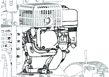
Clean dirt and debris from the engine and the engine-cooling fins (Figure 41).