Installation
Preparing the Machine
-
Park the machine on a level surface.
-
Lower the loader arms.
-
Shut off the engine and remove the key.
-
Open the rear-access cover.
-
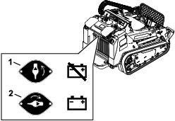
Turn the battery-disconnect switch to the OFF position (Figure 1).
Installing the Lights
Parts needed for this procedure:
| Light | 2 |
| Left light bracket | 1 |
| Right light bracket | 1 |
| Switch | 1 |
| Thread-cutting screw | 2 |
| Bolt (5/16 x 1 inch) | 2 |
| Nut (5/16 inch) | 2 |
-
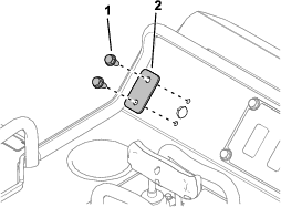
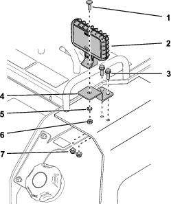
Remove the 2 thread-cutting screws and plate from the control panel (Figure 2). Discard the plate.
-
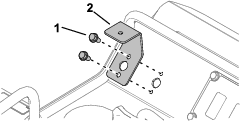
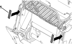
Install the left light bracket using 2 thread-cutting screws (Figure 3).
-
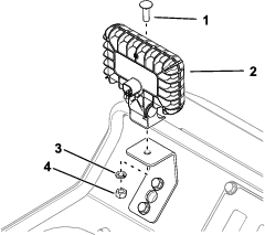
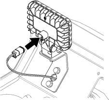
Remove the bolt, washer, and nut from a light and use them to secure the light to the bracket (Figure 4).
-
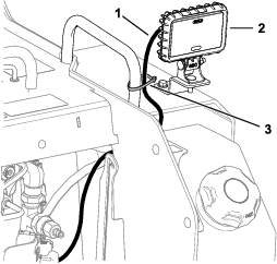
Install the right light bracket to the tower plate using 2 bolts (5/16 x 1 inch) and 2 nuts (5/16 inch) as shown in Figure 5.
-
Remove the bolt and nut from the other light and use them to secure the light to the bracket (Figure 5).
Routing the Wire Harness
Parts needed for this procedure:
| Wire harness | 1 |
| Cable tie | 2 |
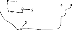
Refer to Figure 6 to identify the wire harness connectors.
-
Remove the 4 thread-cutting bolts (5/16 x 3/4 inch) securing the console plate to the machine (Figure 7).
-
Pull out the plate so that you can access inside the machine.
-
Open the rear-access cover.
-
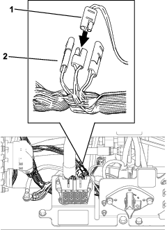
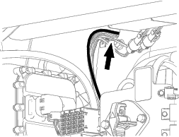
Remove the plug from an accessory connector on the machine wire harness (P50, P75, or P76) and plug the kit wire harness to it (Figure 8).
-
Secure the wire harness to the machine wire harness using a cable tie near the connectors.
-
Route the right light connector out the right side of the machine, up to the light (Figure 9). Plug the connector to the light.
-
Secure the wire harness to the grab bar using a cable tie (Figure 9).
-
Route the left light and switch connectors through the hole on the left side of the machine (Figure 10).
-
Using the console plate opening to access the wire harness, route the left light connector through the hole in the left light bracket and connect it to the left light (Figure 11).
-
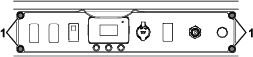
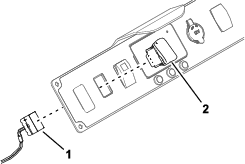
Remove the second plug on the console plate and install the switch (Figure 12). Connect the wire harness to the switch.
-
Secure the console plate to the machine using the 4 thread-cutting bolts removed previously (Figure 7).
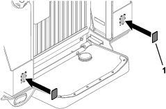
Installing the Reflectors
Completing the Installation
-
Turn the battery-disconnect switch to the ON position and close the rear cover.
-
Start the machine.
-
Use the switch to verify that the lights turn on and off.