| Maintenance Service Interval | Maintenance Procedure |
|---|---|
| Before each use or daily |
|
Introduction
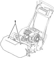
This machine is a walk-behind, reel-blade lawn mower intended to be used by professional, hired operators in commercial applications. It is primarily designed for cutting grass on well-maintained turf. Using this product for purposes other than its intended use could prove dangerous to you and bystanders.
Read this information carefully to learn how to operate and maintain your product properly and to avoid injury and product damage. You are responsible for operating the product properly and safely.
Visit www.Toro.com for product safety and operation training materials, accessory information, help finding a dealer, or to register your product.
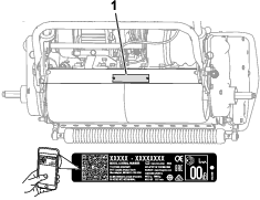
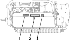
Whenever you need service, genuine Toro parts, or additional information, contact an authorized Toro distributor and have the model and serial numbers of your product ready. The model and serial numbers are located on a plate on the rear frame. Write the numbers in the space provided.
Important: With your mobile device, you can scan the QR code (if equipped) on the serial number decal to access warranty, parts, and other product information.
This manual identifies potential hazards and has safety messages identified by the safety-alert symbol (Figure 2), which signals a hazard that may cause serious injury or death if you do not follow the recommended precautions.

This manual uses 2 words to highlight information. Important calls attention to special mechanical information and Note emphasizes general information worthy of special attention.
This product complies with all relevant European directives; for details, please see the separate product specific Declaration of Conformity (DOC) sheet.
It is a violation of California Public Resource Code Section 4442 or 4443 to use or operate the engine on any forest-covered, brush-covered, or grass-covered land unless the engine is equipped with a spark arrester, as defined in Section 4442, maintained in effective working order, or the engine is constructed, equipped, and maintained for the prevention of fire.
The enclosed engine owner's manual is supplied for information regarding the US Environmental Protection Agency (EPA) and the California Emission Control Regulation of emission systems, maintenance, and warranty. Replacements may be ordered through the engine manufacturer.
Operating this machine 1,500 m (5,000 ft) above sea level requires a high-altitude jet. Refer to your Honda engine owner’s manual.
Warning
CALIFORNIA
Proposition 65 Warning
The engine exhaust from this product contains chemicals known to the State of California to cause cancer, birth defects, or other reproductive harm.
Use of this product may cause exposure to chemicals known to the State of California to cause cancer, birth defects, or other reproductive harm.
Safety
This machine has been designed in accordance with EN ISO 5395 and ANSI B71.4-2017 and meets these standards when you add the Operator Presence Kit and required decals.
General Safety
This product is capable of amputating hands and feet and of throwing objects.
-
Read and understand the contents of this Operator’s Manual before starting the machine.
-
Use your full attention while operating the machine. Do not engage in any activity that causes distractions; otherwise, injury or property damage may occur.
-
Do not put your hands or feet near moving components of the machine.
-
Do not operate the machine without all guards and other safety protective devices in place and functioning properly on the machine.
-
Keep bystanders and children out of the operating area. Never allow children to operate the machine.
-
Shut off the engine, remove the key (if equipped), and wait for all movement to stop before you leave the operator’s position. Allow the machine to cool before adjusting, servicing, cleaning, or storing it.
Improperly using or maintaining this machine can result in injury.
To reduce the potential for injury, comply with these safety instructions
and always pay attention to the safety-alert symbol  , which means
Caution, Warning, or Danger—personal safety instruction. Failure
to comply with these instructions may result in personal injury or
death.
, which means
Caution, Warning, or Danger—personal safety instruction. Failure
to comply with these instructions may result in personal injury or
death.
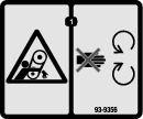
Safety and Instructional Decals
|
Safety decals and instructions are easily visible to the operator and are located near any area of potential danger. Replace any decal that is damaged or missing. |


Setup
Note: Determine the left and right sides of the machine from the normal operating position.
Installing and Adjusting the Handle
Parts needed for this procedure:
| Handle | 1 |
| Cable tie | 4 |
Installing the Handle
-
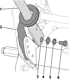
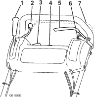
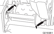
Remove the bolts (5/16 inch), locknuts, ring pins, and hairpin cotters that secure the bottom of the handle arms to each side of the machine (Figure 3).
-
Remove the bolts (3/8 inch), washers, and lock washers from the mounting pins on each side of the machine (Figure 3).
-
Insert the handle ends through the holes in the handle arms and align the holes with the mounting pins (Figure 3).
-
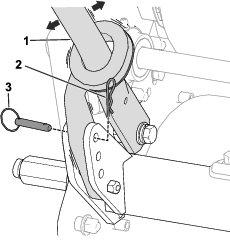
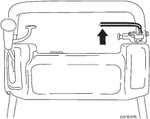
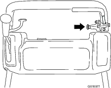
Squeeze the handle ends inward and install them on the mounting pins (Figure 4).
-
Secure the handle to the mounting pins with the bolts (3/8 inch), washers, and lock washers that you previously removed (Figure 4).
-
Use the bolts (5/16 inch), locknuts, hairpin cotters, and ring pins that you previously removed to secure the handle arms to the rear of the frame (Figure 3).
-
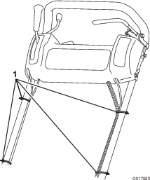
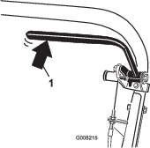
Secure the cables and wire harness to the handle with the cable ties (Figure 5).
Adjusting the Handle
Refer to Figure 6 for this procedure.
-
Remove the hairpin cotters from the ring pins on each side of the machine.
-
While supporting the handle, remove the ring pins from each side and raise or lower the handle to the desired operating position.
-
Install the ring pins and hairpin cotters.
Installing the Transport-Wheel Shafts
Parts needed for this procedure:
| Right wheel shaft | 1 |
| Left wheel shaft | 1 |
-
Push the kickstand down with your foot and pull up on the handle to support the machine on the kickstand.
-
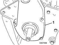
Apply thread-locking adhesive to the threads of the wheel shafts.
-
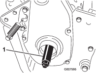
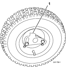
Thread the right wheel shaft into the drive pulley on the right side of the machine (Figure 7).
Note: The right wheel shaft has left-hand threads.
-
Torque the shaft to 88 to 101 N∙m (65 to 75 ft-lb).
-
Repeat steps 2 through 4 to install the left wheel shaft to the left side of the machine.
Installing the Transport Wheels
Optional
Parts needed for this procedure:
| Transport wheel | 2 |
-
Push the kickstand down with your foot and pull up on the handle to support the machine on the kickstand.
-
Slide a wheel onto an axle.
-
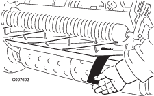
Pivot the wheel locking clip away from center of the wheel, allowing it to slide farther onto the axle (Figure 8).
-
Rotate the wheel back and forth until it slides completely onto the axle and the locking clip is secured in the groove on the axle shaft.
-
Repeat the procedure on the opposite side of the machine.
-
Inflate the tires to 83 to 103 kPa (12 to 15 psi).
-
Carefully lower the machine off the kickstand.
Adjusting the Cutting Unit
Before operating the machine, complete the following adjustments:
Installing the Operator Presence Kit
Parts needed for this procedure:
| Operator Presence Kit (order separately; contact your authorized Toro distributor) | 1 |
To comply with EN ISO 5395 and ANSI B71.4-2017, install the Operator Presence Kit (Model No. 112-9282); refer to the kit Installation Instructions.
Contact your authorized Toro distributor to acquire this kit.
Installing the CE Decals
If Required
Parts needed for this procedure:
| Production-year decal | 1 |
| CE-mark decal | 1 |
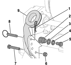
If you use this machine in a country that complies to CE standards, apply the production-year decal and the CE-mark decal near the serial plate; refer to Figure 9.
Installing the Grass Basket
Parts needed for this procedure:
| Grass basket | 1 |
Grasp the basket by the top lip and slide it onto the basket mounting rods (Figure 10).
Breaking in the Machine
Only 8 hours of mowing operation is required for the break-in period.
The first several hours of operation are critical to future dependability of the machine. You must monitor the machine performance closely so that minor difficulties, which could lead to major problems, are noted and can be corrected. During the first few hours of operation, inspect the machine frequently for signs of oil leakage, loose fasteners, or any other malfunction.
Refer to the engine owner’s manual for the recommended break-in-period oil change and maintenance procedures.
Product Overview
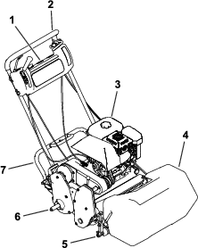
Traction-Drive Lever
The traction-drive lever (Figure 12) is located on the front right side of the control panel. It has 2 positions: NEUTRAL and FORWARD. Pushing the lever forward engages the traction drive.
Throttle Control
The throttle control (Figure 12) is located on the rear, right side of the control panel. The lever connects to and operates the throttle linkage to the carburetor. Refer to Specifications for the engine speed.
On/Off Switch
The On/Off switch (Figure 12) is located on the top of the control panel. Move the switch to the ON position to start the engine and the OFF position to shut off the engine.
Service Brake
The service brake (Figure 13) is located on the top left, front side of the control panel. You can use the brake to slow or stop the machine.
Parking Brake
The parking brake (Figure 14) is located at the base of the service brake. Fully engage the service brake and push the parking-brake knob to allow the service brake to rest on the parking-brake pin. Engage the service brake to release the parking brake. You must release the brake before you engage the traction drive.
Operator-Presence Control
Optional
If equipped, the operator-presence control (Figure 12) is located on the rear of the handle. Push the operator-presence control against the handle. You must engage, the operator-presence control before moving the traction-drive lever. If you release the operator-presence control, the engine shuts off.
Reel-Drive Lever
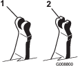
The reel-drive lever (Figure 15) is located on the right, front corner of the machine. The lever has 2 positions:
-
ENGAGE—move the lever forward to engage the reel.
-
DISENGAGE—move the lever rearward to disengage the reel.
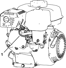
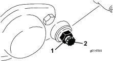
Choke Lever
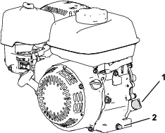
The choke lever (Figure 16) is located on the left front of the engine. Use the lever to aid in starting a cold engine; refer to Using the Choke Lever.
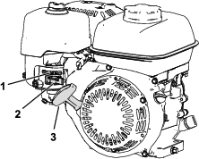
Fuel-Shutoff Valve
The fuel-shut-off valve is located on the side of the engine below the choke control (Figure 16).
Note: Close the fuel-shutoff valve when the machine is not used for a few days, during transport to and from the job site, or when the machine is parked inside a building; refer to Opening and Closing the Fuel-Shutoff Valve.
Recoil-Starter Handle
Pull the recoil-starter handle (Figure 16) to start the engine.
| Model Specifications | Model 04055 |
| Width | 91 cm (36 inches) |
| Height | 114 cm (45 inches) |
| Length with basket | 122 cm (48 inches) |
| Dry weight (with basket and Wiehle roller; without wheels or grooming reel) | 98 kg (216 lb) |
| Width of cut | 53 cm (21 inches) |
| Height of cut | 1.6 mm to 31.8 mm (0.063 to 1.25 inches) |
| Clip | 4.3 mm (0.16 inch) |
| Engine speed | Low idle: 1,800 to 2,000 rpm; High idle: 3,350 to 3,550 rpm |
Attachments/Accessories
A selection of Toro approved attachments and accessories is available for use with the machine to enhance and expand its capabilities. Contact your Authorized Service Dealer or authorized Toro distributor or go to www.Toro.com for a list of all approved attachments and accessories.
To ensure optimum performance and continued safety certification of the machine, use only genuine Toro replacement parts and accessories. Replacement parts and accessories made by other manufacturers could be dangerous, and such use could void the product warranty.
Operation
Note: Determine the left and right sides of the machine from the normal operating position.
Before Operation
Before Operation Safety
General Safety
-
Never allow children or untrained people to operate or service the machine. Local regulations may restrict the age of the operator. The owner is responsible for training all operators and mechanics.
-
Become familiar with the safe operation of the equipment, operator controls, and safety signs.
-
Shut off the engine, remove the key (if equipped), and wait for all movement to stop before you leave the operator’s position. Allow the machine to cool before adjusting, servicing, cleaning, or storing it.
-
Know how to stop the machine and shut off the machine quickly.
-
Check that operator-presence controls, safety switches, and safety protective devices are attached and functioning properly. Do not operate the machine unless they are functioning properly.
-
Inspect the area where you will use the machine and remove all objects that the machine could throw.
Fuel Safety
-
Use extreme care in handling fuel. It is flammable and its vapors are explosive.
-
Extinguish all cigarettes, cigars, pipes, and other sources of ignition.
-
Use only an approved fuel container.
-
Do not remove the fuel cap or add fuel to the tank while the engine is running or hot.
-
Do not add or drain fuel in an enclosed space.
-
Do not store the machine or fuel container where there is an open flame, spark, or pilot light, such as on a water heater or other appliance.
-
If you spill fuel, do not attempt to start the engine; avoid creating a source of ignition until the fuel vapors have dissipated.
-
Do not fill containers inside a vehicle or on a truck or trailer bed with a plastic liner. Always place containers on the ground, away from the vehicle before filling.
-
Remove equipment from the truck or trailer and refuel it on the ground. If this is not possible, refuel such equipment with a portable container rather than from a fuel-dispenser nozzle.
-
Keep the nozzle in contact with the rim of the fuel tank or container operating at all times until fueling is complete.
Performing Daily Maintenance
Perform the daily maintenance procedures; refer to Daily Maintenance Checklist.
Checking the Engine-Oil Level
Check the engine-oil level before each use or every 8 operating hours, refer to Checking the Engine-Oil Level.
Fuel Specifications
Fuel tank capacity: 2.0 L (0.59 US gallons)
Recommended fuel: Unleaded gasoline with an octane rating of 87 or higher ((R+M)/2 rating method)
Ethanol: Gasoline with up to 10% ethanol (gasohol) or 15% MTBE (methyl tertiary butyl ether) by volume is acceptable. Ethanol and MTBE are not the same. Gasoline with 15% ethanol (E15) by volume is not approved for use.
-
Never use gasoline that contains more than 10% ethanol by volume, such as E15 (contains 15% ethanol), E20 (contains 20% ethanol), or E85 (contains up to 85% ethanol).
-
Do not use gasoline containing methanol.
-
Do not store fuel either in the fuel tank or fuel containers over the winter unless a fuel stabilizer is used.
-
Do not add oil to gasoline.
-
For best results, use only clean, fresh (less than 30 days old) fuel.
-
Using unapproved gasoline may cause performance problems and/or engine damage, which may not be covered under the warranty.
Filling the Fuel Tank
Danger
In certain conditions, fuel is extremely flammable and highly explosive. A fire or explosion from fuel can burn you and others and can damage property.
-
Fill the fuel tank outdoors, in an open area, when the engine is cold. Wipe up any fuel that spills.
-
Never fill the fuel tank inside an enclosed trailer.
-
Do not fill the fuel tank completely full. Add fuel to the fuel tank until the level is 6 to 13 mm (1/4 to 1/2 inch) below the bottom of the filler neck. This empty space in the tank allows fuel to expand.
-
Never smoke when handling fuel, and stay away from an open flame or where fuel fumes may be ignited by a spark.
-
Store fuel in an approved container and keep it out of the reach of children. Never buy more than a 30-day supply of fuel.
-
Do not operate without entire exhaust system in place and in proper working condition.
Danger
In certain conditions during fueling, static electricity can be released, causing a spark which can ignite the fuel vapors. A fire or explosion from fuel can burn you and others and can damage property.
-
Always place fuel containers on the ground away from your vehicle before filling.
-
Do not fill fuel containers inside a vehicle or on a truck or trailer bed because interior carpets or plastic truck-bed liners may insulate the container and slow the loss of any static charge.
-
When practical, remove equipment from the truck or trailer and fuel it on the ground. If this is not possible, then fuel such equipment with a portable container rather than from a fuel-dispenser nozzle.
-
If you must use a fuel-dispenser nozzle, keep the nozzle in contact with the rim of the fuel tank or container opening at all times until fueling is complete.
Warning
Fuel is harmful or fatal if swallowed. Long-term exposure to vapors can cause serious injury and illness.
-
Avoid prolonged breathing of vapors.
-
Keep your face away from the nozzle and fuel tank or conditioner bottle opening.
-
Avoid contact with skin; wash off spills with soap and water.
-
Clean around the fuel-tank cap and remove the cap from the tank (Figure 17). Fill the fuel tank to the bottom of the fill-neck opening.
Important: Do not overfill the tank with fuel.
-
Install the fuel-tank cap and wipe up any spilled fuel.
Setting the Machine to Match Turf Conditions
Use the following tables to set the machine to match turf conditions.
| Part Number | Description | Aggressiveness | Comments |
| 112-9281-01 | Standard | Less | Standard Greensmaster 1000 |
| 112-9279-03 | Aggressive | More |
| Part Number | Description | Height of Cut Range | Comments |
| 93-4262 | Microcut | 1.57–3.1 mm (0.062–0.125 inch) | |
| 115-1880 | EdgeMax Microcut | 1.57–3.1 mm (0.062–0.125 inch) | Standard Greensmaster 1000 |
| 93-4263 | Tournament | 3.1–6.0 mm (0.125–0.250 inch) | |
| 115-1881 | EdgeMax Tournament | 3.1–6.0 mm (0.125–0.250 inch) | Longer wearing |
| 93-4264 | Low cut | 6.0 mm (0.250 inch) and up | |
| 108-4303 | Extended Microcut | 1.57–3.1 mm (0.062–0.125 inch) | Less aggressive |
| Part Number | Description | Diameter/Material | Comments |
| 99-6241 | Narrow Wiehle | 50.8 mm (2.0 inches) Aluminum | Standard, 0.20 inch spacing |
| 88-6790 | Wide Wiehle | 50.8 mm (2.0 inches) Aluminum | More penetration, 0.43 inch spacing |
| 104-2642 | Full roller | 50.8 mm (2.0 inches) Steel | Least penetration |
| 71-1550 | Wiehle roller | 50.8 mm (2.0 inches) Cast Iron | More penetration, 0.43 inch spacing |
| 93-9045 | Wiehle roller | 63.5 mm (2.5 inches) Aluminum | 24 inches wide for edge support |
| 52-3590 | Swaged roller | 63.5 mm (2.5 inches) Aluminum |
| Model | Standard | Clip Kit 65-9000 | Traction Kit 115-1886 | Clip and Traction Kits | ||||||||
| Standard reel | Optional reel | Standard reel | Optional reel | Standard reel | Optional reel | Standard reel | Optional reel | |||||
| 04810 | 11-blade4.1 mm (0.16 inch) | 14-blade3.3 mm (0.13 inch) | 8-blade5.8 mm (0.23 inch) | 11-blade6.4 mm (0.25 inch) | 14-blade4.8 mm (0.19 inch) | 8-blade8.6 mm (0.34 inch) | 11-blade3.8 mm (0.15 inch) | 14-blade3.0 mm (0.12 inch) | 8-blade5.1 mm (0.20 inch) | 11-blade5.6 mm (0.22 inch) | 14-blade4.3 mm (0.17 inch) | 8-blade7.6 mm (0.30 inch) |
| Ground speed | 5.39 km/h (3.35 mph) | 4.80 km/h (2.98 mph) | ||||||||||
Checking the Interlock-Switch Operation
Caution
If the safety interlock switches are disconnected or damaged, the machine could operate unexpectedly causing personal injury.
-
Do not tamper with the interlock switches.
-
Check the operation of the interlock switches daily and replace any damaged switches before operating the machine.
-
Push the kickstand down with your foot and pull up and back on the handle to raise the wheels off the ground.
-
Place the traction lever into the ENGAGE position and the engine controls in the starting position.
-
Attempt to start the engine.
The engine should not start. If the engine starts, the interlock switch needs service. Correct the problem before operating the machine. Refer to Servicing the Traction-Interlock Switch
-
Carefully lift up on the handle to release the kickstand.
Transporting the Machine to a Job Site
Transporting the Machine Using Transport Wheels
Use the transport wheels to transport the machine a shorter distance.
-
Install the transport wheels; refer to Installing the Transport Wheels
-
Ensure that the traction and reel-drive controls are in the NEUTRAL position.
-
Start the engine; refer to Starting the Engine
-
Set the throttle control to SLOW, tip the front of the machine up, gradually engage the traction drive, and slowly increase the engine speed.
-
Adjust the throttle to operate the mower at the desired ground speed and transport the machine to the desired destination.
Transporting the Machine Using a Trailer
Use a trailer to transport the machine a considerable distance. Use caution while loading and unloading the machine onto the trailer.
-
Carefully drive the machine onto the trailer.
-
Shut off the engine, engage the parking brake, and turn the fuel valve to the OFF position.
-
Use a full-width ramp for loading the machine into a trailer or truck.
-
Securely fasten the machine to the trailer.
Note: You can use the Toro Trans Pro trailer to transport the machine. For instructions on loading the trailer, refer to your trailer Operator’s Manual.
Important: Do not run the engine while transporting it on a trailer because damage can occur to the machine.
Removing the Transport Wheels
-
Return the traction control lever to the NEUTRAL position, the throttle to the SLOW position, and shut off the engine.
-
Push the kickstand down with your foot and pull up on the handle support until the kickstand has rotated forward, over center.
-
Remove the transport wheels by pushing the wheel locking clips out of the hex-shaft grooves.
-
Carefully lower the machine off of the kickstand by pushing forward slowly or by lifting the lower handle support, allowing the kickstand to spring back to the STORAGE position.
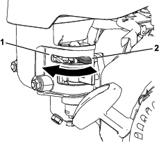
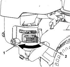
Using the Choke Lever
Use the choke lever to aid in starting a cold engine. Move the lever to the CHOKE position when starting a cold engine. After the engine starts, move the lever to the RUN position.
Opening and Closing the Fuel-Shutoff Valve
During Operation
During Operation Safety
General Safety
-
The owner/operator can prevent and is responsible for accidents that may cause personal injury or property damage.
-
Wear appropriate clothing, including eye protection; long pants; substantial, slip-resistant footwear; and hearing protection. Tie back long hair and do not wear loose clothing or loose jewelry.
-
Do not operate the machine while ill, tired, or under the influence of alcohol or drugs.
-
Use your full attention while operating the machine. Do not engage in any activity that causes distractions; otherwise, injury or property damage may occur.
-
Before you start the machine, ensure that all drives are in neutral, the parking brake is engaged, and you are in the operating position.
-
Keep bystanders and children out of the operating area. If co-workers must be present, use caution and ensure that the grass basket is installed on the machine.
-
Operate the machine only in good visibility to avoid holes or hidden hazards.
-
Do not operate the machine when there is the risk of lightning.
-
Avoid mowing on wet grass. Poor footing could cause a slip-and-fall accident.
-
Keep your hands and feet away from the cutting unit.
-
Look behind and down before backing up to be sure of a clear path.
-
Use care when approaching blind corners, shrubs, trees, or other objects that may obscure your vision.
-
Stop the cutting unit whenever you are not mowing.
-
Disengage the drive to the cutting unit and shut off the engine before adjusting the height of cut.
-
Never run an engine in an area where exhaust gasses are enclosed.
-
Never leave a running machine unattended.
-
Before you leave the operator’s position, do the following:
-
Park the machine on a level surface.
-
Disengage the cutting unit.
-
Engage the parking brake.
-
Shut off the machine and remove the key (if equipped).
-
Wait for all movement to stop.
-
-
Shut off the machine before emptying the basket.
-
Do not touch the engine, muffler, or exhaust pipe while the engine is running or soon after it has shut off because these areas could be hot enough to cause burns.
-
Shut off the machine and disengage the drive to the cutting unit in the following situations:
-
Before fueling
-
Before clearing blockages
-
Before removing the grass basket
-
Before checking, cleaning, or maintaining the cutting unit
-
After striking a foreign object or if an abnormal vibration occurs. Inspect the cutting unit for damage and make repairs before starting and operating the machine
-
Before leaving the operating position
-
-
Use only accessories and attachments approved by The Toro® Company.
Slope Safety
-
Slopes are a major factor related to loss of control and rollover accidents, which can result in severe injury or death. You are responsible for safe slope operation. Operating the machine on any slope requires extra caution. Before using the machine on a slope, do the following:
-
Review and understand the slope instructions in the manual and on the machine.
-
Evaluate the site conditions of the day to determine if the slope is safe for machine operation. Use common sense and good judgment when performing this evaluation. Changes in the terrain, such as moisture, can quickly affect the operation of the machine on a slope.
-
-
Operate across slopes, never up and down. Avoid operation on excessively steep or wet slopes. Poor footing could cause a slip-and-fall accident.
-
Identify hazards at the base of the slope. Do not operate the machine near drop-offs, ditches, embankments, water, or other hazards. The machine could suddenly roll over if a wheel goes over the edge or the edge collapses. Keep a safe distance between the machine and any hazard. Use a handheld tool to operate in these areas.
-
Avoid starting, stopping, or turning the machine on slopes. Avoid making sudden changes in speed or direction; turn slowly and gradually.
-
Do not operate a machine under any conditions where traction, steering or stability is in question. Be aware that operating the machine on wet grass, across slopes or downhill may cause the machine to lose traction. Loss of traction to the drive wheels may result in sliding and a loss of braking and steering. The machine can slide even if the drive wheels are stopped.
-
Remove or mark obstacles such as ditches, holes, ruts, bumps, rocks, or other hidden hazards. Tall grass can hide obstacles. Uneven terrain could overturn the machine.
-
If you lose control of the machine, step away from the direction of travel of the machine.
-
Always keep the machine in gear when going down slopes. Do not coast downhill (applicable only to gear-drive units).
Starting the Engine
Note: For illustrations and descriptions of the controls referenced in this section, refer to Controls.
Note: Ensure that the spark-plug wire is installed on the spark plug.
-
Ensure that the traction and reel drive levers are in the DISENGAGED position.
Note: The engine will not start if the traction lever is in the ENGAGED position.
-
Ensure that the fuel-shutoff valve is open.
-
Move the On/Off switch to the ON position.
-
Move the throttle control to the FAST position.
-
Move the choke lever halfway between the CHOKE and RUN positions when starting a cold engine.
Note: The choke may not be required when starting a warm engine.
-
Pull the recoil-start handle out until positive engagement results, then pull it vigorously to start the engine.
Important: Do not pull the recoil rope to its limit or let go of the starter handle when the rope is pulled out; the rope may break or the recoil assembly may be damaged.
-
Move the choke lever to the RUN position as the engine warms up.
Shutting Off the Engine
-
Move the traction and reel drive controls to the DISENGAGED position.
-
Move the throttle control to the SLOW position.
-
Move the On/Off switch to the OFF position.
-
Close the fuel-shutoff valve before you store or transport the machine
Operating Tips
Important: Grass clippings act as a lubricant when mowing. Operating the cutting unit excessively without grass clippings can damage the cutting unit.
-
Mow the greens in a straight back-and-forth direction across the green.
-
Avoid circular mowing or turning the machine on the greens areas to prevent scuffing.
-
Turn the machine off the green by raising the cutting reel (pushing the handle down) and turning on the traction drum.
-
Mow at a normal walking pace. Fast speeds saves little time and results in an inferior mowing job.
-
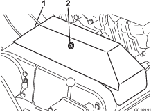
To assist in maintaining a straight line across the green and to keep the machine an equal distance from the edge of the previous cut, use the alignment stripes on the basket (Figure 20).
Operating the Machine in Low Light Conditions
Use the LED Light Kit when you operate the machine in low light conditions; contact your authorized Toro distributor.
Important: Do not use other light systems with this machine, as they will not operate properly with the engine AC output.
Mowing
Proper use of the machine provides the smoothest turf cutting available. Refer also to Operating Tips for fundamental suggestions to obtain the utmost performance from your machine.
Important: Excessive operation of the cutting unit with the absence of grass clippings (lubricant) can damage the cutting unit.
-
Start the engine, set the throttle at a reduced speed, push down on the handle to raise the cutting unit, move the traction lever to the ENGAGED position, and transport the machine onto the collar of the green.
-
Move the traction lever to the DISENGAGED position and move the reel-drive lever to the ENGAGED position.
-
Move the traction lever to the ENGAGED position, increase the throttle speed until the machine is traveling at the desired ground speed, drive the machine onto the green, lower the front of the machine, and commence operation.
-
When you are finished mowing, drive off the green, move the traction-control lever to the DISENGAGED position, shut off the engine, and push the reel-drive lever into the DISENGAGED position.
-
Empty the grass basket of clippings, install the grass basket, and commence the transport operation.
Operating the Controls after Mowing
-
Drive off the green, move the reel drive and traction control levers to the DISENGAGED position, and shut off the engine.
-
Empty the grass basket of clippings, install the grass basket on the mower, and transport the machine to storage.
After Operation
After Operation Safety
General Safety
-
Shut off the engine, remove the key (if equipped), and wait for all movement to stop before you leave the operator’s position. Allow the machine to cool before adjusting, servicing, cleaning, or storing it.
-
Clean grass and debris from the machine to help prevent fires. Clean up oil or fuel spills.
-
Allow the machine to cool before storing the machine in any enclosure.
-
Do not store the machine or fuel container where there is an open flame, spark, or pilot light, such as on a water heater or on other appliances.
-
Reduce the throttle setting before shutting off the engine and turn off the fuel-shutoff valve (if equipped) after mowing.
Transporting the Machine
After mowing, transport the machine away from the job site; refer to Transporting the Machine Using Transport Wheels or Transporting the Machine Using a Trailer.
Maintenance
Warning
Failure to properly maintain the machine could result in premature failure of machine systems causing possible harm to you or bystanders.
Keep the machine well maintained and in good working order as indicated in these instructions.
Note: Determine the left and right sides of the machine from the normal operating position.
Important: Do not tip the machine at an angle greater than 25°. Tipping the machine beyond 25° leads to oil leaking into the combustion chamber and/or fuel leaking out of the fuel-tank cap.
Important: Refer to your engine Owner’s Manual for additional maintenance procedures.
Maintenance Safety
-
Before you leave the operator’s position, do the following:
-
Park the machine on a level surface.
-
Move the throttle to the low-idle position.
-
Disengage the cutting unit(s).
-
Ensure that the traction is in neutral.
-
Engage the parking brake.
-
Shut off the machine and remove the key (if equipped).
-
Wait for all movement to stop.
-
-
Allow machine components to cool before performing maintenance.
-
If possible, do not perform maintenance while the machine is running. Keep away from moving parts.
-
If the engine must be running to perform a maintenance adjustment, keep your hands, feet, clothing, and any parts of the body away from the cutting unit, attachments, and any moving parts. Keep bystanders away.
-
Clean grass and debris from the cutting unit, drive, muffler, cooling screen, and the engine to help prevent fires. Clean up oil or fuel spills.
-
Keep all parts in good working condition. Replace all worn, damaged, or missing parts and decals. Keep all hardware tight to ensure that the machine is in safe working condition.
-
Check the grass catcher components frequently and replace them when necessary.
-
To ensure safe, optimal performance of the machine, use only genuine Toro replacement parts. Replacement parts made by other manufacturers could be dangerous, and such use could void the product warranty.
-
If major repairs are ever needed or if assistance is desired, contact an authorized Toro distributor.
Recommended Maintenance Schedule(s)
| Maintenance Service Interval | Maintenance Procedure |
|---|---|
| After the first 20 hours |
|
| Before each use or daily |
|
| Every 25 hours |
|
| Every 50 hours |
|
| Every 100 hours |
|
| Every 300 hours |
|
| Every 1,000 hours |
|
Pre-Maintenance Procedures
Preparing the Machine for Maintenance
Warning
While you are maintaining or adjusting the machine, someone could start the engine. Accidentally starting the engine could seriously injure you or other bystanders.
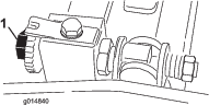
Shut off the engine, engage the parking brake, and pull the wire(s) off the spark plug(s) before you do any maintenance. Also push the wire(s) aside so it does not accidentally contact the spark plug(s).
Perform the following before servicing, cleaning, or making any adjustments to the machine.
-
Park the machine on a level surface.
-
Shut off the engine and remove the key from the machine (if equipped).
-
Engage the parking brake.
-
Wait for all moving parts to stop allow the engine to cool before servicing, storing, or making repairs.
-
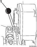
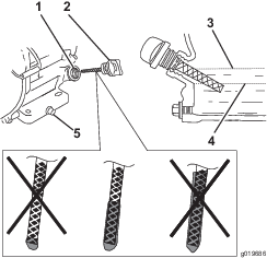
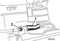
Disconnect the spark-plug wire (Figure 21).
Lubrication
Greasing the Machine
| Maintenance Service Interval | Maintenance Procedure |
|---|---|
| Every 25 hours |
|
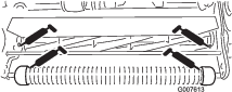
Lubricate the 12 grease fittings on the mower using No. 2 lithium grease. For best results, use a hand-operated grease gun.
The grease fitting locations are as follows:
-
2 on the front roller (Figure 22)
-
2 on the reel bearings (Figure 22)
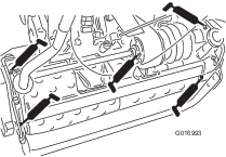
-
2 on the drum axles (Figure 23)
-
3 on the differential (Figure 23)
-
2 on the reel countershaft bearings (Figure 24)
-
1 on the belt idler pivots (Figure 25).
-
Wipe each grease fitting with a clean rag.
-
Pump grease into each fitting.
Important: Do not apply too much pressure or the grease seals may become permanently damaged.
-
Wipe off any excess grease.
Engine Maintenance
Engine Safety
-
Do not change the governor speed or overspeed the engine.
-
Run the engine dry or remove the fuel with a hand pump; never siphon the fuel. If you must drain the fuel tank, do it outdoors.
Servicing the Engine Oil
Fill the crankcase with approximately 0.56 L (19 fl oz) of the proper viscosity oil before starting. The engine uses a high-quality oil that has the American Petroleum Institute (API) service classification of SJ or higher. Select the proper oil viscosity (weight) based on the ambient temperature. Figure 26 illustrates the temperature/viscosity recommendations.
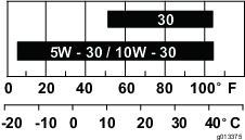
Note: Multi-grade oils (5W-20, 10W-30 and 10W-40) increase oil consumption. Check the engine-oil level more frequently when you use these oils.
Checking the Engine-Oil Level
| Maintenance Service Interval | Maintenance Procedure |
|---|---|
| Before each use or daily |
|
The ideal time to check the engine-oil level is when the engine is cool or before you have started the engine for the day. If you have already ran the engine, allow the oil to drain back down to the sump for at least 10 minutes before you check the engine-oil level.
-
Shut off the engine and wait for all moving parts to stop; refer to Preparing the Machine for Maintenance.
-
Position the machine so that the engine is level, and clean the area around the oil-fill tube (Figure 27).
-
Remove the dipstick by rotating it counterclockwise.
-
Remove the dipstick and wipe the end clean.
-
Insert the dipstick fully into the oil-fill tube, but do not thread it in.
-
Remove the dipstick and check the engine-oil level (Figure 28).
-
If the engine-oil level is incorrect, add or drain oil to correct the level; refer to Changing the Engine Oil.
Changing the Engine Oil
| Maintenance Service Interval | Maintenance Procedure |
|---|---|
| After the first 20 hours |
|
| Every 100 hours |
|
Warning
Oil may be hot after the engine has been run, and contact with hot oil can cause severe personal injury.
Avoid contacting the hot engine oil when you drain it.
-
Shut off the engine and wait for all moving parts to stop; refer to Preparing the Machine for Maintenance.
-
Place a pan under the drain plug to catch the oil.
-
Remove the drain plug, washer, and dipstick (Figure 27).
-
Position the engine so that the oil drains from the engine.
-
When the oil has drained completely, move the engine to a level position and install the drain plug and a new washer.
Note: Dispose of the used oil at a certified recycling center.
-
Slowly pour oil into the oil-fill hole until the oil is at the correct level.
-
Ensure that the oil is at the correct level on the dipstick; refer to Checking the Engine-Oil Level.
-
Thread the dipstick into the oil-fill hole.
-
Wipe up any spilled oil.
-
Connect the wire to the spark plug.
Servicing the Air Cleaner
| Maintenance Service Interval | Maintenance Procedure |
|---|---|
| Before each use or daily |
|
| Every 50 hours |
|
| Every 300 hours |
|
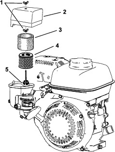
Important: Do not operate the engine without the air filter assembly; extreme engine damage will occur.
-
Shut off the engine and wait for all moving parts to stop; refer to Preparing the Machine for Maintenance.
-
Remove the wingnut securing the air-cleaner cover (Figure 29).
-
Remove the air-cleaner cover.
Note: Ensure that no dirt or debris from the air-cleaner cover fall into the base.
-
Remove the foam and paper elements from the base.
-
Remove the foam element from the paper element.
-
Inspect the foam and paper elements; replace them if they are damaged or excessively dirty.
-
Clean the paper element by tapping it gently to remove the dirt.
Note: Do not try to brush dirt off the paper element; brushing forces the dirt into the fibers. Replace the element if tapping it fails to remove the dirt.
-
Clean the foam element in warm, soapy water or in a nonflammable solvent.
Note: Do not use gasoline to clean the foam element because it could create a risk of fire or explosion.
-
Rinse and dry the foam element thoroughly.
-
Wipe dirt from the base and the cover with a moist rag.
Note: Ensure that dirt and debris do not enter the air duct leading to the carburetor.
-
Install the air-cleaner elements and ensure that they are properly positioned. Install the lower wing nut.
-
Install the cover and install the upper wing nut to secure it.
Servicing the Spark Plug
| Maintenance Service Interval | Maintenance Procedure |
|---|---|
| Every 100 hours |
|
| Every 300 hours |
|
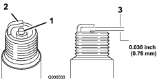
Use an NGK BPR6ES spark plug or equivalent.
-
Shut off the engine and wait for all moving parts to stop; refer to Preparing the Machine for Maintenance.
-
Clean around the spark plug.
-
Remove the spark plug from the cylinder head.
Important: Replace a cracked, fouled, or dirty spark plug. Do not sand blast, scrape, or clean the electrodes because engine damage could result from grit entering the cylinder.
-
Set the gap on the plug to 0.7 to 0.8 mm (0.028 to 0.031 inch)
-
Carefully install the spark plug by hand (to avoid cross threading) until it is hand tight.
-
Tighten the spark plug an additional 1/2 turn if it is new; otherwise, tighten it an additional 1/8 to 1/4 turn.
Important: A loose spark plug can become very hot and can damage the engine; overtightening a spark plug may damage the threads in the cylinder head.
-
Connect the wire to the spark plug.
Electrical System Maintenance
Servicing the Traction-Interlock Switch
Use the following procedure if the traction-interlock switch needs adjustment or replacement.
-
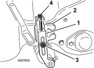
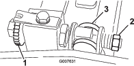
Ensure that the engine is off and the traction lever is disengaged and resting against the neutral stop (Figure 31).
-
Loosen the interlock switch mounting fasteners (Figure 31).
-
Place a 0.8 mm (0.032 inch) thick shim between the traction lever and the interlock switch (Figure 31).
-
Tighten the interlock switch mounting fasteners and check the gap again.
Note: The traction lever must not contact the switch.
-
Engage the traction lever and verify that the switch loses continuity.
Note: Replace the switch if necessary.
Brake Maintenance
Adjusting the Service/Parking Brake
If the service/parking brake slips during operation, adjust it.
-
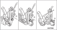
Engage the service brake, push in the parking brake knob, and allow the service brake to rest on the parking-brake pin (Figure 32).

-
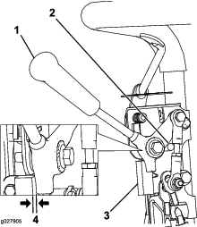
Using a spring scale, press rearward on the service-brake lever (Figure 33). The parking brake should release when a force of 13.5 to 18 kg (30 to 40 lb) is attained. If the parking brake releases before 13.5 to 18 kg (30 to 40 lb) of force is attained, adjust the brake cable.
-
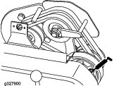
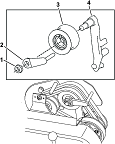
Loosen the retainer that secures the V-belt cover and pivot the cover open (Figure 34).
-
To adjust the brake cable tension, proceed as follows.
-
To decrease the cable tension, loosen the front cable jam nut and tighten the rear jam nut (Figure 35). Repeat steps 1 and 2 and adjust the tension if necessary.
-
To increase the cable tension, tighten the front cable jam nut and loosen the rear jam nut (Figure 35). Repeat steps 1 and 2 and adjust the tension if necessary.
Note: You can adjust the cable at the jam nut brackets by the control panel or at the bracket at the base of the engine.
-
-
Close the cover and secure the retainer.
Belt Maintenance
Adjusting the Belts
Ensure that the belts are properly tensioned to ensure proper operation of the machine and prevent unnecessary wear. Check the belts frequently.
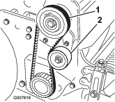
Adjusting the Reel-Drive Belt
-
Remove the belt-cover mounting fasteners and the belt cover to expose the belt (Figure 36).
-
Check the tension by pressing the belt at mid-span of the pulleys (Figure 37) with 18 to 22 N (4 to 5 lb) of force. The belt should deflect 6 mm (1/4 inch).
-
Complete the following steps to adjust the belt tension:
-
Loosen the idler-pulley mounting nut and pivot the idler pulley clockwise against the backside of the belt until you attain the desired belt tension (Figure 37).
Important: Do not over-tension the belt.
-
Tighten the nut to lock the adjustment.
-
-
Install the belt cover by placing it in position.
-
While maintaining a slight gap between the cover seal and the side plate, install each mounting bolt until the threads engage in the insert.
Note: The gap allows visual alignment of the bolts to the threaded inserts.
-
After all bolts are installed, tighten them until the stand-offs inside the cover contact the side plate.
Note: Do not overtighten the bolts.
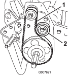
Adjusting the Traction-Drive Belt
-
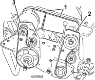
Remove the belt-cover mounting fasteners and the belt cover to expose the belt (Figure 38).
-
Check the tension by pressing the belt at mid span of the pulleys (Figure 39) with 18 to 22 N (4 to 5 lb) of force.
Note: The belt should deflect 6 mm (1/4 inch).
-
Complete the following to adjust the belt tension:
-
Loosen the idler-pulley mounting nut and pivot the idler pulley clockwise against the backside of the belt until the desired belt tension is attained (Figure 39).
Important: Do not over-tension the belt.
-
Tighten the nut to lock the adjustment.
-
-
Install the belt cover by placing it in position.
-
While maintaining a slight gap between the cover seal and the side plate, install each mounting bolt until the threads engage in the insert.
Note: The gap allows visual alignment of the bolts to the threaded inserts.
-
After all bolts are installed, tighten them until the stand-offs inside the cover contact the side plate.
Note: Do not overtighten the bolts.
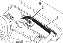
Adjusting the Differential Belt
-
Remove the bolts securing the front and rear sections of the differential cover to the differential housing and slide the cover sections away to expose the belt.
-
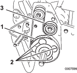
Check the tension by pressing the belt at mid span of the pulleys (Figure 40) with 22 to 26 N (5 to 6 lb) of force.
Note: The belt should deflect 6 mm (1/4 inch).
-
Complete the following to adjust the belt tension:
-
Loosen the idler pulley mounting nut and pivot the idler pulley clockwise against the backside of the belt until the desired belt tension is attained (Figure 40).
Important: Do not over-tension the belt.
-
Tighten the nut to lock the adjustment.
-
-
Install the belt cover by placing it in position.
-
While maintaining a slight gap between the cover seal and the side plate, install each mounting bolt until the threads engage in the insert. The gap allows visual alignment of the bolts to the threaded inserts.
-
After all bolts are installed, tighten them until the stand-offs inside the cover contact the side plate. Do not overtighten the bolts.
Adjusting the Primary V-Belts
-
To adjust the belt tension on primary V-belts, first check the adjustment of the traction control; refer to Adjusting the Traction Control.
If the belts still slip after you adjust the traction control, proceed to the next step.
-
Loosen the retainer that secures the V-belt cover and pivot the cover open (Figure 41).
-
To increase the belt tension, loosen the engine mounting bolts and move the engine backwards in the slots.
Important: Do not over-tension the belt.
-
Tighten the mounting bolts.
Note: The distance between the center of the drive pulley and the center of the driven pulley should be approximately 12.7 cm (5 inches) after the new V-belts are installed.
-
After tensioning the primary V-belts, check the alignment of the engine output-shaft pulley and the counter-shaft pulley with a straightedge.
-
If the pulleys are misaligned, loosen the screws that secure the engine mounting base to the machine frame and slide the engine from side to side until the pulleys are aligned within 0.7 mm (0.030 inch).
-
Tighten the mounting screws and check the alignment.
-
To push or pull the machine easier without starting the engine, adjust the belt guide (Figure 42, inset) as follows:
-
Engage the clutch.
-
Loosen the locknut that secures the idler pulley and the belt guide to the idler arm.
-
Rotate the belt guide clockwise until a gap of approximately 1.5 mm (0.06 inch) is obtained between the guide finger and the backside of the drive belts.
-
Tighten the locknut that secures the idler pulley and the belt guide to the idler arm.
-
-
Close the cover and secure the retainer.
Replacing the Differential Belt
-
Remove the bolts that secure the traction drive and reel-drive belt covers to the right side plate and remove the belt covers.
-
Loosen the idler pulley mounting nut on each idler pulley and pivot each idler pulley counterclockwise away from the backside of each belt to release the belt tension.
-
Remove the belts.
-
Remove the bolts that secure the front and rear sections of the differential cover to the differential housing and slide the cover sections away to expose the belt (Figure 43).
-
Loosen the idler pulley mounting nut on the differential idler pulley and pivot the idler pulley counterclockwise away from the backside of the belt to release the belt tension.
-
Remove the 2 bolts and 2 locknuts that secure the front clutch housing to the side plate (Figure 43).
-
Rotate the housing 180° so that the bottom of the housing points upward.
-
Remove the 2 bolts and 2 locknuts that secure the right rear bearing housing to the side plate (Figure 43).
-
Rotate the housing 180° so that the bottom of the housing points upward.
-
Remove the old belt.
-
Slide the new belt over the rotated housing covers, the differential cover sections, and onto the differential pulleys.
-
Ensure that the idler pulley is positioned against the backside of the belt.
-
Rotate both housings back into the upright position and secure them to the side plate with the bolts and nuts that you previously removed.
-
Adjust the differential belt tension; refer to Adjusting the Differential Belt.
-
Adjust the belt tension on the traction drive and reel-drive belts; refer to Adjusting the Traction-Drive Belt, and Adjusting the Reel-Drive Belt.
-
Install the differential, traction drive, and reel-drive covers.
Controls System Maintenance
Adjusting the Traction Control
Follow these steps to remove slack from the traction control:
-
Move the traction control to the DISENGAGED position.
-
Loosen the retainer that secures the V-belt cover and pivot the cover open (Figure 41).
-
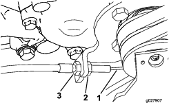
To remove slack from the traction control, loosen the front-cable jam nut and tighten the back-cable jam nut (Figure 44) until all slack is removed.
-
Tighten the front-cable jam nut.
-
Close the cover and secure the retainer.
-
Check the traction-control operation.
Cutting Unit Maintenance
Blade Safety
Use care when checking the cutting-unit reel. Wear gloves and use caution when servicing the reel.
A worn or damaged blade or bedknife can break, and a piece could be thrown toward you or bystanders, resulting in serious personal injury or death.
-
Inspect the blades and bedknives periodically for excessive wear or damage.
-
Use care when checking the blades. Wear gloves and use caution when servicing them. Only replace or backlap the blades and bedknives; never straighten or weld them.
Leveling the Rear Drum to the Reel
-
Park the machine on a flat, level surface, preferably a precision steel work plate.
-
Place a 0.6 x 2.5 cm (1/4 x 1 inch) flat steel strip, approximately 73.6 cm (29 inches) long, under the reel blades and against the front edge of the bedknife to prevent the bedbar from resting on the work surface.
-
Raise the front roller so that only the rear drum and the reel are on the surface.
-
Firmly press down on the machine above the reel so that all reel blades contact the steel strip.
-
While pressing down on the reel, slide a feeler gauge under one end of the drum, then check the other end of the drum.
Note: If there is a gap between the drum and the work surface, greater than 0.25 mm (0.010 inch), on either end, adjust the drum (proceed to step 6). If the gap is less than 0.25 mm (0.010 inch), no adjustment is required.
-
Remove the rear belt cover from the right side of the machine (Figure 45).
-
Rotate the driven pulley until the holes align with the 4 roller bearing flange screws (Figure 46).
-
Loosen the 4 roller bearing screws and the screw that secures the idler pulley.
-
Raise or lower the right side of the roller assembly until the gap is less than 0.25 mm (0.010 inch).
-
Tighten the roller bearing screws.
-
Adjust the belt tension and tighten the idler pulley mounting screw (Figure 46).
Adjusting the Bedknife to the Reel
Adjust the bedknife to the reel after grinding, backlapping, or disassembling the cutting unit. This procedure is not intended as a daily adjustment.
-
Park the machine on a flat, level work surface.
-
Tilt the machine back on the handle to expose the bedknife and the reel.
Important: Do not tip the machine at an angle greater than 25°. Tipping the machine beyond 25° leads to oil leaking into the combustion chamber and/or fuel leaking out of the fuel-tank cap.
-
Rotate the reel so that a blade crosses the bedknife edge between the first and second bedknife screw heads on the right side of the cutting unit (Figure 47).
-
Rotate the reel so that a blade crosses the bedknife edge between the first and second bedknife screw heads on the right side of the cutting unit.
-
Insert the 0.05 mm (0.002 inch) shim between the marked blade and the bedknife edge at the point where the marked blade crosses the bedknife edge.
-
Turn the right bedbar-adjusting screw until you feel light pressure (i.e., drag) on the shim by sliding it side-to-side (Figure 47).
-
Remove the shim.
-
For the left side of the cutting unit, slowly rotate the reel so that the closest blade crosses the bedknife edge between the first and second screw heads.
-
Repeat steps 4 through 7 for the left side of the cutting unit and left bedbar-adjusting screw.
-
Repeat steps 5 through 7 until light drag is achieved on both the right and left sides of the cutting unit utilizing the same contact points.
-
To obtain light contact between the reel and bedknife, turn each bedbar-adjusting screw clockwise 3 clicks.
Note: Each click turned on the bedbar-adjusting screw moves the bedknife 0.018 mm (0.0007 inch). Clockwise rotation moves the bedknife edge closer to the reel and counterclockwise rotation move the bedknife edge away from the reel.
-
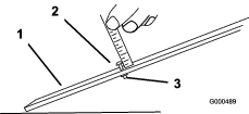
Test the cutting performance by inserting a long strip of cutting performance paper between the reel and bedknife, perpendicular to the bedknife (Figure 48). Slowly rotate the reel forward; it should cut the paper.
Note: If you see excessive contact/reel drag, it will be necessary to backlap, face the front of the bedknife, or grind the cutting unit to achieve the sharp edges that are necessary for precise cutting.
Adjusting the Height-of-Cut
-
Verify that the rear roller is level and that the bedknife-to-reel contact is correct. Tip the machine back on the handle to expose the front and rear rollers and the bedknife.
Important: Do not tip the machine at an angle greater than 25°. Tipping the machine beyond 25 ° leads to oil leaking into the combustion chamber and/or fuel leaking out of the fuel-tank cap.
-
Loosen the locknuts that secure the height-of-cut arms to the height-of-cut brackets (Figure 49).
-
Loosen the nut on the gauge bar (Figure 50) and set the adjusting screw to the desired height-of-cut. The distance between the bottom of the screw head and the face of the bar is the height of cut.
-
Hook the screw head on the cutting edge of the bedknife and rest the rear end of the bar on the rear roller (Figure 51).
-
Rotate the adjusting screw until the roller contacts the front of the gauge bar.
-
Adjust both ends of the roller until the entire roller is parallel to the bedknife.
Important: When set properly, the rear and front rollers contact the gauge bar and the screw is snug against the bedknife. This ensures that the height-of-cut is identical at both ends of the bedknife.
-
Tighten the nuts to lock the adjustment.
Important: To avoid scalping on undulating turf, ensure that the roller supports are positioned rearward (the roller closer to the reel).
Note: The front roller can be put in 3 different positions (Figure 52), depending on the application and needs of the user.
-
Use the front position when a groomer is installed.
-
Use the middle position without a groomer.
-
Use the third position in extremely undulating turf conditions.
-
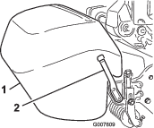
Adjusting the Grass Shield Height
Adjust the shield to ensure proper grass clipping discharge into the basket.
-
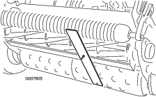
Measure the distance from the top of the front support rod to the front lip of the shield at each end of the cutting unit (Figure 53).
-
The height of the shield from the support rod for normal cutting conditions should be 10 cm (4 inches). Loosen the bolts and nuts that secure each end of the shield to the side plate and adjust the shield to the correct height.
-
Tighten the fasteners.
Note: You can lower the shield for dry turf conditions (clippings fly over the top of the basket) or raise it to allow for heavy, wet grass conditions (clippings build up on the rear of the basket).
Adjusting the Cut-Off Bar
Adjust the cut-off bar to ensure that the clippings are cleanly discharged from the reel area.
-
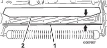
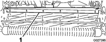
Loosen the screws that secure the top bar (Figure 54) to the cutting unit.
-
Insert a 1.5 mm (0.060 inch) feeler gauge between the top of the reel and the bar and tighten the screws.
-
Ensure that the bar and reel are equal distances apart across the entire reel.
Note: The bar is adjustable to compensate for changes in turf conditions. Adjust the bar closer to the reel when the turf is extremely wet. By contrast, adjust the bar further away from the reel when turf conditions are dry. The bar should be parallel to the reel to ensure optimum performance. Adjust the bar when you adjust the shield height or when you sharpen the reel on a reel grinder.
Identifying the Bedbar
To determine if the bedbar is standard or aggressive, check the left bedbar mounting ears. If the mounting ears are rounded, it is a standard bedbar. If the mounting ears have a notch in them, it is an aggressive bedbar (Figure 55).
Servicing the Bedbar
Removing the Bedbar
-
Turn the bedbar-adjuster screw counterclockwise to back the bedknife away from the reel (Figure 56).
-
Back out the spring-tension nut until the washer is no longer tensioned against the bedbar (Figure 56).
-
On each side of the machine, loosen the jam nut that secures the bedbar bolt (Figure 57).
-
Remove each bedbar bolt allowing the bedbar to be pulled downward and removed from the machine. Save the 2 nylon and 2 stamped steel washers on each end of the bedbar (Figure 57).
Installing the Bedbar
-
Install the bedbar, positioning the mounting ears between the washer and the bedbar adjuster.
-
Secure the bedbar to each side plate with the bedbar bolts (jam nuts on the bolts) and 8 washers.
Note: Position a nylon washer on each side of the side plate boss. Place a steel washer outside each of the nylon washers.
-
Torque the bolts to 27 to 36 N∙m (20 to 27 ft-lb).
-
Tighten the jam nuts until the outside thrust washers just rotate freely.
-
Tighten the spring-tension nut until the spring is collapsed, then back it off 1/2 turn.
-
Adjust the bedbar; refer to Adjusting the Bedknife to the Reel.
Backlapping the Reel
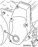
-
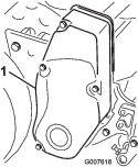
Remove the plug in the right reel-drive cover (Figure 58).
-
Insert a 1/2 inch-drive extension bar, connected to the backlapping machine, into the square hole in the center of the reel pulley.
-
Backlap according to the procedure in the Toro Sharpening Reel and Rotary Mowers Manual, Form 80-300 PT.
Danger
Contact with the reel or other moving parts can result in personal injury.
-
Stay away from the reel while backlapping.
-
Do not use a short-handled paint brush for backlapping. Part No. 29-9100 Handle assembly, complete or as individual parts, are available from your local authorized Toro distributor.
Note: For a better cutting edge, run a file across the front face of the bedknife when the lapping operation is completed. This removes any burrs or rough edges that may have built up on the cutting edge.
-
-
Install the plug in the cover when you complete this procedure.
Storage
Storage Safety
-
Shut off the engine, remove the key (if equipped), and wait for all movement to stop before you leave the operator’s position. Allow the machine to cool before adjusting, servicing, cleaning, or storing it.
-
Do not store the machine or fuel container where there is an open flame, spark, or pilot light, such as on a water heater or other appliance.
Storing the Machine
-
Remove any grass clippings, dirt, and grime from the external parts of the entire machine, especially the engine. Clean the dirt and chaff from the outside of the engine cylinder-head fins and the blower housing.
Important: You can wash the machine with mild detergent and water. Do not pressure-wash the machine. Avoid excessive use of water, especially near the shift-lever plate and the engine.
-
For long-term storage (more than 30 days) add stabilizer/conditioner additive to the fuel in the tank.
-
Run the engine to distribute conditioned fuel through the fuel system for 5 minutes.
-
Either shut off the engine, allow it to cool, and drain the fuel tank, or operate the engine until it shuts off.
-
Start the engine and run it until it shuts off. Start the engine again, with the choke closed, until the engine does not start.
-
Disconnect the spark-plug wire from the spark plug.
-
Dispose of the fuel properly. Recycle it according to local codes.
Note: Do not store fuel containing stabilizer/conditioner longer than the duration recommended by the fuel-stabilizer manufacturer.
-
-
Check and tighten all bolts, nuts, and screws. Repair or replace any part that is worn or damaged.
-
Paint all scratched or bare metal surfaces. Paint is available from your authorized Toro distributor.
-
Store the machine in a clean, dry garage or storage area. Cover the machine to protect it and keep it clean.