Installation
Preparing the Machine
-
Park the machine on a level surface.
-
Lower the loader arms.
-
Remove any attachments; refer to the Operator’s Manual for the machine.
-
Shut off the engine and remove the key.
Removing the Existing Pivot Pin
-
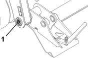
On each side of the attachment mount plate, remove the bolt (5/16 x 2-1/2 inches), locknut (5/16 inch), and link pin securing the hydraulic cylinder rod to the mount plate (Figure 1).

-
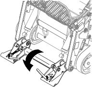
Rotate the attachment mount plate forward so that it is resting on the ground (Figure 2).
-
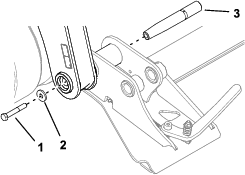
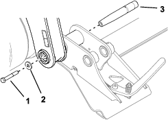
On 1 side of the mount plate, loosen the bolt (1/2 x 3-1/4 inch) securing the pivot pin so that the head of the bolt is at least 6 mm (1/4 inch) out from the original position (Figure 3).
-
Use a hammer to strike the head of the bolt to push the pivot pin toward the middle of the machine.
-
When the pivot pin is removable, remove the bolt, washer, and pivot pin (Figure 4).
-
Repeat steps 4 through 7 for the other pivot pin.
-
Check the pivot bushings of the attachment mount plate for wear or damage. Replace any as necessary.
Installing the New Pivot Pins
-
Install the grease fittings onto the new pins.
-
Align the holes in the loader arms with the holes in the attachment mount plate.
-
On both sides of the attachment mount plate, slide the tapered end of the pivot pin into the holes from the inside of the attachment mount plate.
-
Ensure that the taper on the pins and the holes are clean and free of grease.
-
Apply thread-locking compound to the bolts (1/2 x 3-1/2 inches), and secure each pin with a bolt and washer as shown in Figure 5. Torque the bolts to 127 to 157 N∙m (94 to 116 ft-lb).
-
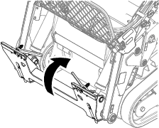
Rotate the attachment mount plate up toward the loader arms (Figure 6).
-
Insert the hydraulic cylinder rods into the attachment mount plate and secure them with the link pins, bolts (5/16 x 2-1/2 inches), and locknuts (5/16 inch) removed previously (Figure 7). Torque the locknuts to 20 to 25 N∙m (15 to 18 ft-lb).
-
Grease the base and rod end of the hydraulic cylinders and the pivot pins.
-
Start the machine and tilt the attachment mount plate forward and rearward to verify that it operates properly.