Read this information carefully to learn how to operate the InfoCenter control on your product. You are responsible for operating the product properly and safely.
Visit www.Toro.com for product safety and operation training materials, accessory information, help finding a dealer, or to register your product.
Introduction
This guide provides information on using the system information and controling the system functions.
Product Overview
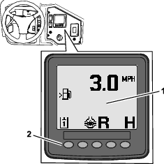
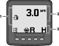
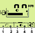
InfoCenter Startup Screen
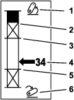
When you start the machine, the startup screen appears, displaying the corresponding mode icons that apply.
Note: The following figure is an example screen; this screen shows potential icons that could appear on the screen while operating.Refer to the Symbols Glossary for all the icon meanings.
From the any modes home screen, press any button to access the pop-up menu bar at the bottom of the screen (Figure 1).
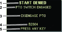
Advisory Example
Advisories communicate helpful information about normal machine behavior. An advisory is basic information noting the computer has detected the machine has an incorrect operating condition. Follow the instructions on the screen to correct the issue. The graphic below shows a sample of what an advisory displays on the screen.
Note: Usually, an advisory is a temporary response to an operator action and explains why it has prevented an action.
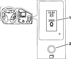
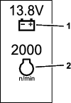
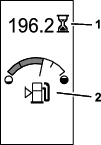
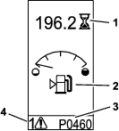
Status Display
This display allows you to view the fuel level, coolant temperature, hydraulic-fluid temperature, battery voltage, engine speed, the 3-point maximum height for transporting, and the maximum and minimum height for running a 3-point, PTO attachment. This also displays all the active machine or engine fault codes (Figure 9).
Push the status display switch to toggle through the different available screens. See the following figures for the available screens.
Note: See your authorized Toro distributor for the Fault Code Manual or the Yanmar® engine manual for engine faults.

Operation
Symbols Glossary
The following table shows the possible symbols for the InfoCenter.
 | Attachment |
 | Alert |
 | Battery |
 | Brightness/Contract |
 | Brightness |
 | Contrast |
 | Engine coolant temperature |
 | Cruise control |
 | Select/Change |
 | Attachment mode |
 | Delete |
 | Scroll up |
 | Scroll down |
 | Edit the attachment |
 | Hydraulic circuit 1 |
 | Hydraulic circuit 2 |
 | More options above |
 | More options below |
 | Maintenance |
 | Service menu |
 | Increase value |
 | Decrease value |
 | Next screen |
 | Previous screen |
 | Engine oil pressure |
 | PTO enabled |
 | PTO engaged |
 | Exhaust filter regeneration is inhibited |
 | Exhaust filter regeneration is acknowledged |
 | Exhaust temperature is high due to the regeneration |
 | Parked or recovery regeneration icon—regeneration is requested. |
| Perform the regeneration immediately. | |
 | NOx control system malfunction; the machine requires service. |
 | Save |
 | Hour meter |
 | Forward |
 | Auto high mode |
 | Auto low mode |
 | Reverse |
 | Neutral |
 | Glow plugs are active |
 | Move the screen curser left |
 | Move the screen curser right |
 | Hydraulic-fluid temperature |
 | Differential lock |
 | Stop safely as soon as possible |
 | Fuel level |
 | Cancel |
 | Enter |
| Symbols are often combined to form sentences. An example is shown below: | |
 | The machine hours indicate there is regular service needed |
Navigating in the InfoCenter
Use the following icons to navigate through screens in the InfoCenter. These are used with the buttons on the bottom of the InfoCenter display.
| Icon | |
| Scroll up |
| Scroll down |
| Next screen |
| Previous screen |
| Move the screen curser left |
| Move the screen curser right |
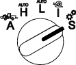
Using the Operation-Mode Selector
Note: The machine must come to a stop before you can change the modes.
Use the mode selector to change the machine operation status or to set up attachments. The modes are as follows:
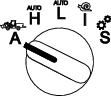
Attachment Mode
Use Attachment Mode to select the specific type of attachment or when attachments are installed and being moved to the work site. To access Attachment Mode, turn the operation-mode selector to the position (Figure 10).
Note: Changing attachments mounted to the Outcross may require the input of a pin number.
Note: Driving the machine in Attachment Mode operates the same as driving in Low Automotive Mode when the PTO switch is in the OFF AND DISABLED position and the auxiliary hydraulic lever is in the NEUTRAL position.
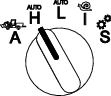
High Automotive Mode
Use High Automotive Mode to drive the machine similar to a passenger vehicle with an automatic transmission. This mode provides the capacity for higher speed but lower power to the ground. Use this mode to efficiently transport yourself, a passenger, and a light payload.
To access High Automotive Mode, turn the operation-mode selector to the position (Figure 11).
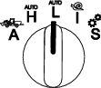
Low Automotive Mode
Use Low Automotive Mode to drive the machine similar to a passenger vehicle with an automatic transmission. This mode provides the capacity for higher payloads or steeper hill climbing speed at a lower ground speed. Use this mode to efficiently transport heavier payloads or trailers.
To access Low Automotive Mode, turn the operation-mode selector to the position (Figure 12).
InchMode
Note: The InchMode setting is available through the use of an optional kit; see your authorized Toro distributor for more information.
Use the InchMode setting to aid in the connection of attachments to the machine. To access the InchMode setting, turn the operation-mode selector to the position (Figure 13).
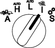
To aid in the connection of attachments, locate and use the tethered remote to direct the machine forward or reverse, and to lift and lower the 3-point hitch. You can also engage the PTO.
Setup Mode
Use Setup Mode to access machine settings, service details, and basic machine information. You can also add or adjust the operational parameters of an attachment.
You can also use Setup Mode to attach and configure attachments. The engine stays at low idle when pressing the accelerator pedal and slowly moves the machine forward or in reverse. Pulling the PTO switch out engages the PTO (regardless of the current PTO parameter setting) and use the paddle to raise or lower the 3-point hitch.
To access Setup Mode, turn the operation-mode selector to the position (Figure 14).
The following are possible in Setup Mode:
-
You can move the vehicle at a very low speed and low engine rpm.
-
You can lift and lower the 3-point hitch beyond the settings allowed for the current attachment.
-
You can engage the PTO output at a low engine rpm with the PTO switch.
Accessing the Protected Menus
Note: The factory default PIN code for you machine is either 0000 or 1234.If you changed the PIN code and forgot it, contact your authorized Toro distributor.
-
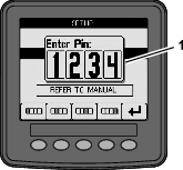
In the Setup mode, press any button to access the pop-up menu bar at the bottom of the screen (Figure 15).
-
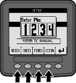
Press buttons as shown in Figure 16 to enter your PIN code.
-
When you complete entering the PIN, select the enter icon (Figure 17).
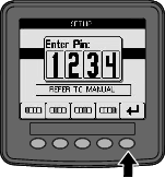
Note: Entering the PIN allows access to configure the machine until you turn the key to the OFF position.
Setting the InfoCenter Units and Language
-
Rotate the operation-mode selector to the S position (Figure 18).
-
Select the SETTINGS option from the display menu and select the next screen icon
 .
. -
Enter the PIN number (Figure 15) and select the ENTER icon
 .
. -
Scroll down to INFOCENTER option and select the next screen icon.
-
For changing the language, scroll down to the LANGUAGE option, select the next screen icon, scroll down to the desired InfoCenter language, and select the change icon
 .
. -
For changing the units, scroll down to the UNITS option and select the IMP or METRIC option with the change icon
. -
Select the previous screen icon
 .
.
Setting the Service-Due Indicator
The InfoCenter indicates the time until the next regular service interval.
Use the InfoCenter along with the operation-mode selector to change the service interval after maintenance.
-
Rotate the operation-mode selector to the S position (Figure 19).
-
Scroll down, select the SERVICE option from the display menu, and select the next screen icon
. -
Enter the PIN number (Figure 15) and select the RETURN icon.
-
Scroll down, select the SCHEDULE option from the display menu, and select the next screen icon.
-
Scroll down to the service procedure performed (i.e. oil filter or grease points) and select the next screen icon.
-
Select the hour interval and select the change icon (
) to reset
the hours for that procedure. -
Select the save icon
 .
.
Audible Alarms
The machine alarm sounds when the operator is out of the seat and one of the following situations occur:
-
The traction is engaged.
-
The shift lever is not in neutral.
-
The auxiliary hydraulic lever is not in neutral position and the parking brake is off.
-
The PTO switch is on and the parking brake is off.
The machine alarm sounds when:
-
The InchMode is active and you press the InchMode enable switch on the control box.
-
The hydraulic temperature is too high.
-
The machine is in the attachment mode and the ground speed is below the minimum work speed.
-
The engine oil pressure is low.
The InfoCenter sounds a beep (usually not heard when the machine is in operation) when a fault or an advisory occurs. Refer to Figure 3 for an example of an advisory.
Changing the InfoCenter Display Brightness/Contrast
You can access the brightness and contrast in the attachment, auto high, auto low, and inchmode. Select the far right button to select the icon brightness/contrast icon.
-
Select the brightness/contrast icon from the pop-up-menu bar.
-
Use the plus and minus icons to change the brightness/contrast pop-up-menu bar (Figure 20).
Setting Up Parameters
To access the parameters, rotate the operation-mode selector to the S position (Figure 21).
Using the Machine Parameters
Machine parameters are parameters that control functions of the machine and not a specific attachment.
Maximum Auto High Ground Speed
This allows the supervisor to limit the machine ground speed when the machine is in the High Automotive mode. It is adjustable from 1.6 to 33.8 km/hr (1 to 21 mph) in 0.16 km/hr (0.1 mph) increments.
Maximum Auto Low Ground Speed
This allows the supervisor to limit the machine ground speed when the machine is in the Low Automotive mode. It is adjustable from 1.6 to 12.9 km/hr (1 to 8 mph) in 0.16 km/hr (0.1 mph) increments.
Inch Mode
Select enable or disable.
Using the Attachment Parameters
This machine is unique in that each attachment is set up before use and stored in the machine computer. The attachment parameters set the limits for each attachment used with this machine.
Note: Ensure that the parking brake is engaged when the operator is out of the seat when using a stationary attachment.
The following are characteristics of parameters.
-
The parameters are protected by PIN settings for supervisor control when security is turned on.
-
The parameters are the options on different screens and every attachment does not use all parameters.
-
The parameter choices are dependent on the selection of the location, power source, engagement method, and rate control.
-
You can save 16 different active attachments in the machine computer.
Use the instructions on the screen to guide you through and select the different parameters.
Attachment Location
This is the location where an attachment is connected to the machine. The following are the different options:
-
3-POINT—the attachment is connected the 3-point hitch
-
OTHER—the attachment is any attachment not connected to the 3-point hitch
Attachment Power Source
This is the power source the attachment uses. The following are the different options:
-
NO POWER—the attachment requires no PTO or hydraulic power (i.e. the attachment uses the draw bar or the loader joystick, if installed)
-
PTO—the attachment requires PTO power only
-
HYDRAULIC—the attachment requires hydraulic power only
-
BOTH—the attachment requires both hydraulic and PTO power. This could be a combination of 2 attachments.
Note: Selecting both means your attachment or multiple attachments require continuous hydraulic flow and PTO engagement. Attachments that use momentary hydraulic flow to lift and lower do not necessarily fall under this category. Selecting both allows the machine to change engine speed anytime the hydraulic auxiliary power or PTO output are engaged.
Engagement Method
This defines the engagement of PTO powered attachments and if they are engaged by the paddle or a switch.
-
The PADDLE CONTROL is typically used for 3-point attachments to automatically control the 3-point hitch height, the allowed PTO run height, the PTO start up, the PTO delay to lower, the PTO speed, the ground speed limit, the turnaround position, and ground speed; all with just the tap of the paddle control.
Note: The PADDLE CONTROL function is not available when using a stationary attachment.
-
The SWITCH CONTROL is the traditional PTO engagement method and is only controlled by the PTO switch or the hydraulic auxiliary switch.
Note: Ensure the parking brake is engaged when the operator is out of the seat when using a stationary attachment.
Rate Control
This consists of POWER CONTROL, AUTOMOTIVE CONTROL, and RATE CONTROL. This determines how the engine and traction speed are controlled. The types of rate control are as follows:
-
POWER CONTROL—the ground speed is variable through the traction pedal and the engine speed is locked when either the PTO or the hydraulic auxiliary switch is engaged or enabled. This is used for attachments that require a constant PTO speed and hydraulic flow. Possible uses would be a pull-behind mower or debris blower.
-
AUTOMOTIVE CONTROL—both the engine speed and the ground speed are variable through the traction pedal when either the PTO or the hydraulic auxiliary switch is engaged. The PTO speed varies with engine speed. Possible uses for this parameter include a 3-point fertilizer spreader in which you need to slow the PTO speed to reduce spreader throwing distance or to slow the machine to maintain safe machine operation.
You can set the minimum speed alarm to remind the operator to maintain speed as soon as it is safe to do so.
Note: With the proper parameter settings, you can set the maximum operating speed and set the warning buzzer for the minimum speed. Set the minimum speed buzzer to remind the operator to maintain speed as soon as it is safe to do so.
-
RATE CONTROL—the engine speed is locked and the ground speed is limited and locked to the speed set in the parameters when the PTO or the hydraulic auxiliary is engaged. Possible uses for this parameter are an aerator or spreader when it is safe to do so.
Note: If rate control is selected, the machine must be moving to employ the attachment. Use this setting for rate-critical attachments.
Decel Response
This controls the reaction time of the machine when you release the traction pedal.
The types of response are as follows:
-
LOW—traction slows gradually when you release the traction pedal. This response rate is like operating a car.
-
MEDIUM—traction slows moderately when you release the traction pedal. This response is like operating a hydrostatic drive machine.
-
HIGH—traction slows most quickly when you release the traction pedal. This response is recommended when using a loader.
Maximum Transport Speed
This is the maximum ground speed during transport. This is used when in ATTACHMENT MODE but the PTO and the hydraulic auxiliary switch are disengaged. It is adjustable from 1.6 to 33.8 km/hr (0.5 to 8 mph) in 0.16 km/hr (0.1 mph) increments. Adjust this for each attachment and use a slower speed for large and heavy attachments.
Maximum Reverse Speed
This is the maximum reverse speed as a percentage of the maximum transport speed. It is adjustable from 10 to 100% in 10% increments. The recommended use is 50% or less for most attachments. Use lower speeds when operating the loader and higher speeds when using a snow blade.
Maximum Turnaround Speed
This parameter is required only for 3-point attachments engaged by the paddle. This is the maximum ground speed when the attachment is lifted to the 3-point turnaround position. It is adjustable from 0.8 km/hr (0.5 mph) to maximum transport speed in 0.16 km/hr (0.1 mph) increments. Use a lower speed when the weight and size of the attachment is large.
When using an attachment that requires a low groundspeed, such as an aerator, you typically speed up to turn around at the end of a pass. When using a faster ground speed attachment, you typically turn around slower to avoid damaging the turf or to maneuver safely.
Maximum Work Speed
This is the maximum ground speed when the attachment is engaged.
You can adjust the rate of an attachment by changing ground speed. For a power attachment, limit the speed to allow for appropriate performance, such as a mower attachment.
Minimum Work Speed
This is the desired minimum ground speed when the attachment is engaged. An alarm sounds and text display occurs when the ground speed goes below this setting. It is adjustable from 0.0 to 0.8 km/hr (0.0 to 0.5 mph) below the maximum work speed in 0.16 km/hr (0.1 mph) increments. Refer to the manual for each attachment used to prevent damage to the attachment.
Work Speed Adjustment Span
This parameter only applies to attachments with RATE CONTROL. This parameter allows the supervisor to configure the ground speed range they allow the operator to have when operating a rate-controlled attachment. This range allows the operator to change the work speed by pressing the plus or minus button next to the cruise control only within the range. You cans set the range between 0 and 1.6 km/hr (0 to 1 mph) in 0.16 km/hr (0.1 mph) increments to maintain the exact maximum work speed. You use this on an attachment like an aerator or top dresser. When operating the Toro 1298 aerator, a speed range of 0.16 km/hr (0.1 mph) allows the operator to change the spacing 4.8 mm (3/16 inch) wider or 4.8 mm (3/16 inch) narrower than the parameter setting. If the supervisor sets this range to 0, the operator cannot change the spacing in any direction.
Using the Status Display to Record the Three-Point Positions
Note: Ensure that the PTO drive shafts do not bottom out and cause damaged to the machine or the attachment. See the attachment manual for the proper setup for the drive-line angles and drive-line length.
-
Review your attachment manual to ensure the drive-shaft length is correct and for the correct operation positions.
-
Start the Outcross machine and cycle through the screens on the status display to show the 3-point hitch height (Figure 22).
-
Move the 3-point hitch up and down and record the number for the current hitch position when in the transport position, the turn around position, the maximum work position, and the minimum work position (Figure 22).
Three-Point Transport Position
This is the maximum lift height of a 3-point attachment. Set this position by lifting the attachment to the maximum height allowed or the highest angle for a non-engaged PTO shaft; whichever occurs first. Note the height position on the status display screen and enter it into the parameter setting in the InfoCenter screen (Figure 22).
Three-Point Turn Around Position
This parameter is only required for 3-point attachments engaged by the paddle. This is the automatic position of the 3-point when the attachment is in turn around or being lifted to avoid a hazard. Set this point by lifting the 3-point attachment and confirm that the lifted attachment does not damage the natural swales of the turf. Note the height position on the Status Display screen and enter it into the parameter setting in the InfoCenter screen (Figure 22).
Three-Point Max Work Position
This is the highest 3-point hitch position that the PTO is allowed to rotate when engaged.
Note: Raise the attachment and verify that the PTO drive shaft does not bottom out or separate by exceeding the maximum extension.
Raise the attachment to the highest allowed point and note the height position on the Status Display screen and enter it into the parameter setting in the InfoCenter screen (Figure 22).
For paddle controlled attachments, set this height greater than 3-point turn around position if you want the attachment to continue to run during the turn around. The range is 0 to maximum transport height in increments of 1.
For switch controlled attachments, ensure that the 3-point hitch is between the maximum and minimum work positions to engage the PTO. Once it is engaged, it cannot be raised higher until you shut off the PTO.
Note: Set this position at a lower number than 3-point turn around position for the attachment to shutoff during the turnaround of the machine.
Three-Point Min Work Position
This is the lowest 3-point hitch position that the PTO is allowed to rotate when engaged.
Note: Lower the attachment and verify that the PTO drive shaft does not bottom out or separate by exceeding the maximum extension.
Lower the attachment to the lowest, allowed point and note the height position on the Status Display screen and enter it into the parameter setting in the InfoCenter screen (Figure 22).
For paddle engaged attachments, this is the working position with the PTO engaged. This prevents the attachment from going lower than this height due to the PTO angle being too severe at lower angles.
For switch engaged attachments, ensure that the 3-point hitch is between the maximum and minimum work positions to engage the PTO. Once it is engaged, this is the minimum height the attachment is allowed to be engaged.
Set this to 0, to have the attachment work in the float position.
The range is 0 to 3 point max work position in increments of 1. If the PTO is off, lowering the attachment below this position is possible. You cannot engage the PTO below the minimum work position.
Setting this position prevents damaging the attachments that depend on the height off the ground. An example is a debris blower.
Drop Speed
This controls the 3-point lower rate. It is adjustable from 10 to 100% in 10% increments.
This helps prevent damage to turf when dropping the attachment into the turf.
Note: The speed is relatively consistent regardless of the attachment weight or the engine rpm.
Use a faster drop speed only when a quick response is required and the turf is not damaged by the dropping of the attachment.
Raise Speed
This controls the 3-point raise rate. It is adjustable from 10 to 100% in 10% increments.
Note: The speed is affected by the engine rpm. A slower engine speed results in slower raise speeds.
Application Power Source Speed
-
PTO POWER—this is the PTO shaft speed when the attachment is in the work position. The engine speed adjusts to meet this speed. It is adjustable from 220 to 540 rpm in 5 rpm increments.
-
HYDRAULIC POWER—this is the engine speed when the attachment uses hydraulics and is in the work position. The engine speed will modify to meet this speed. Engine speed is adjustable from 1200 to 3000 rpm in 100 rpm increments.
Note: The minimum engine speed is affected by the air conditioning, automatic DPF cleaning, or the hydraulic fluid temperature.
Lifted Power Source Speed
This only applies to paddle engaged attachments.
-
PTO power—this is the PTO shaft speed when the attachment is in the turnaround position. The engine speed will modify to meet this speed. It is adjustable from 220 to 540 rpm in 5 rpm increments.
-
Hydraulic power—this is the engine speed when the attachment uses hydraulics and is in the turn-around position. The engine speed will modify to meet this speed. Engine speed is adjustable from 1,200 to 3,000 rpm in 100 rpm increments.
PTO Engagement Rate
This controls the speed at which the PTO reaches its programmed speed.
The types of response are as follows:
-
STANDARD—the PTO engages right away and the engine ramps up to the application-power source speed.
-
MEDIUM—when the PTO input is engaged, the engine rpm reduces and dwells a short time, before ramping up to the application-power source speed. This is used for belt driven attachments with heavy starting inertia. An example of this would be a debris blower.
-
LOW—when the PTO input is engaged, the engine rpm drops and dwells a long time, before ramping up very slowly to the application-power source speed. This response is rarely used.
Delay Lower Time
Note: This parameter only applies to the paddle-engaged attachments.
This is the amount of time, in seconds, the 3-point dwells before lowering to the work position. This allows the PTO to reach full speed before the attachment engages the ground. It is adjustable from 0 to 25 seconds in 0.1 second increments.
Use this for attachments like a 3-point rotary mower or a deep tine aerator, that require time to get to full speed.
Delay Turnaround Time
This is the amount of time, in seconds, the PTO remains running once the 3-point hitch reaches the 3-point max work position or turnaround position. This allows unstable attachments to briefly run out of the ground to avoid hazards or irrigation heads. If the attachment is allowed to remain running in turn around, it is adjustable from 0 to 25 seconds in 0.1 increments.
Use this for attachments that engage the ground like an aerator or a seeder.
Note: The turnaround speed is not active until this timer has expired. Once this time has elapsed, the machine can speed up if you press the pedal to maximize the speed.
Delay then Raise Time
This is the amount of time, in seconds, the 3-point dwells before lifting the attachment to the turnaround position. This allows the attachment to stop before raising above the maximum, 3-point PTO height. It is adjustable from 0 to 25 seconds in 0.1 increments. This prevents damage to the PTO shaft, the machine, or the attachment.
Attachment Minimum Engine Speed
This is the minimum engine speed allowed when you install the attachment. It is adjustable from 1,200 to 3,000 rpm in 100 rpm increments.
Note: Use a higher engine speed to provide adequate ground power when the attachment is heavy or if you will encounter many inclines.
Note: The PTO engagement rate is affected when the attachment-minimum engine speed is higher than 1,800 rpm.
Examples of Setting Up an Attachment
Ensure you use the attachment manual when you are setting up an attachment in the InfoCenter. Using the attachment manual will help guide you in selecting the parameters.
The following are 2 examples of setting up an attachment. Use these examples as possible parameters that you could use for attachments.
Setting up a Toro 1298 ProCore Aerator
-
Move the operation-mode selector to the SETUP position.
-
Select the SETTING option from the display menu and select the next screen icon
. -
Enter the PIN number (Figure 15) and select the RETURN icon.
-
Scroll down (
 ) to ATTACHMENTS option
and select the next screen icon .
) to ATTACHMENTS option
and select the next screen icon . -
Select the ADD NEW option, select the TORO option, and choose the Toro attachement—ProCore 1298.
-
Select the next screen button.
-
For the location, select the 3-POINT option and select the next screen icon.
-
Select the PTO power source from the following options:
-
NO POWER
-
PTO
-
HYDRAULIC
-
BOTH
-
-
Select the next screen icon.
-
Select the PADDLE engagement method and select the next screen icon.
-
Scroll down and select the RATE CONTROL and select the next screen icon.
-
Select the LOW decel response and select the next screen icon.
-
LOW
-
MEDIUM
-
HIGH
-
-
Set the max transport speed by using the plus or minus icons (
 )
and select the next screen icon.
)
and select the next screen icon. -
Set the reverse speed by using the plus or minus icons and select the next screen icon.
-
Set the max turn-around speed by using the plus or minus icons and select the next screen icon.
-
Set the max work speed by using the plus or minus icons and select the next screen icon.
-
Set the work speed adjustment span by using the plus or minus icons and select the next screen icon.
-
Set the 3-point transportation position by using the plus or minus icons and select the next screen icon.
-
Set the 3-point turn-around position by using the plus or minus icons and select the next screen icon.
-
Set the 3-point maximum work position by using the plus or minus icons and select the next screen icon.
-
Set the 3-point minimum work position by using the plus or minus icons and select the next screen icon.
-
Set the drop speed by using the plus or minus icons and select the next screen icon.
-
Set the raise speed by using the plus or minus icons and select the next screen icon.
-
Set the PTO shaft speed by using the plus or minus icons and select the next screen icon.
-
Set the lifted PTO shaft speed by using the plus or minus icons and select the next screen icon.
-
Scroll down and select the STANDARD rate out of the following options and select the next screen icon.
-
LOW
-
MEDIUM
-
STANDARD
-
-
Set the delay lower time by using the plus or minus icons and select the next screen icon.
-
Set the delay turn-around time by using the plus or minus icons and select the next screen icon.
-
Set the delay raise time by using the plus or minus icons and select the next screen icon.
-
Set the minimum engine speed by using the plus or minus icons and select the next screen icon.
-
Enter the name of the attachment.
-
Enter the name of the attachment by using the arrow icons. When you move the cursor to the letter you want, press the lower right button to select that letter.
-
Select the save icon
.
-
-
Confirm the save by selecting the save icon
. -
Turn the mode selector knob the ATTACHMENT position (Figure 24).
Setting up a 3 Point Spreader
-
Turn the mode selector knob the SETUP position
-
Select the SETTING option from the display menu and select the next screen icon
. -
Enter the PIN number (Figure 15) and select the RETURN icon
. -
Scroll down (
) to ATTACHMENTS option
and select the next screen icon . -
Select the ADD NEW option and select the next screen icon.
-
Select the OTHER option.
-
For the location, select the 3-POINT option and select the next screen icon.
-
Select the power source as the PTO and select the next screen icon.
-
Select the engagement method as SWITCH and select the next screen icon.
Note: The attachment engages when you turn the PTO switch on.
-
Scroll down and select RATE CONTROL and select the next screen icon.
-
Select the decel response time of LOW and select the next screen icon.
-
Set the max transport speed desired and select the next screen icon.
-
Set the reverse speed desired and select the next screen icon.
-
Set the max work speed desired and select the next screen icon.
-
Set the work speed adjustment span and select the next screen icon.
-
Set the 3-point transport position and select the next screen icon.
-
Set the 3-point maximum work position and select the next screen icon.
-
Set the 3-point minimum work position and select the next screen icon.
-
Set the drop speed and select the next screen icon.
-
Set the raise speed select the next screen icon.
-
Set the PTO shaft speed and select the next screen icon.
-
Set the PTO engagement speed to STANDARD from the following options and select the next screen icon.
-
LOW
-
MEDIUM
-
STANDARD
-
-
Set the delay then raise time and select the next screen icon.
-
Set the minimum engine speed and select the next screen icon.
-
Enter the name of the attachment.
-
Enter the name of the attachment by using the arrow icons. When you move the cursor to the letter you want, press the lower right button to select that letter.
-
Select the save button
.
-
-
Confirm the save by selecting the save icon
. -
Turn the mode selector knob the attachment position.