Read this information carefully to learn how to operate and maintain your product properly and to avoid injury and product damage. You are responsible for operating the product properly and safely.
Whenever you need service, genuine Toro parts, or additional information, contact an Authorized Service Dealer or Toro Customer Service and have the model and serial numbers of your product ready.
You may contact Toro directly at www.Toro.com for product safety and operation training materials, accessory information, help finding a dealer, or to register your product.
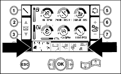
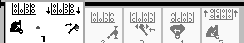
Main Information Screen
This is the first screen that appears after the initial splash screen. To navigate between screens, use the left and right arrows.
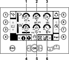
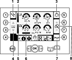
Go to the Mud or Air Hammer Selection Screen to switch between mud pressure and air hammer functions.
Push button 1 to switch between the pipe functions pull pipe, push pipe, and neutral.
Push button 5 to switch between thrust force, drill speed (rpm), and rotary torque limits.
Use the up and down arrows to set the limits for maximum drill speed (rpm), rotary torque, and thrust force.
-
Thrust force: Change the thrust force limit by pushing 6 or 7.
-
Drill speed (rpm): Change the drill speed rpm limit by pushing 6 or 7.
-
Rotary torque: Change the rotary torque limit force by pushing 6 or 7.
SmartTouch
SmartTouch mode allows the operator to load and unload pipes from the rod box with less joystick operation to reduce operator fatigue.
Use the Carriage Settings Screen to turn SmartTouch mode on and off.
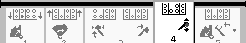
Note: The Push/Pull Icons have a green background when SmartTouch mode is on and a ribbon appears at the bottom of the screen showing a sequence of the steps.
Important: Never switch between Push/Pull modes during the chosen operation. Use neutral (manual) mode to switch between Push/Pull; refer to Carriage Settings Screen to turn SmartTouch mode off.
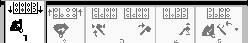
The SmartTouch screens appears along the bottom of the home screen as shown below.
Pulling Pipe in SmartTouch Mode
Start the SmartTouch mode with the cam assembly in the home position (row 4 of the pipe box).
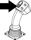
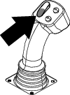
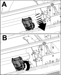
Important: Ensure that you hold the lower section of the cam rocker switch, on the left joystick, completely down until the action is complete in each step (Figure 5).
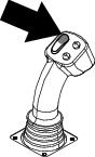
Hold the upper section of the cam rocker switch, on the left joystick, completely down until all actions are complete to go to the previous step in the sequence (Figure 6).
-
Push button 1 to select the pull pipe option (Figure 7).
-
Push buttons 2 and 3 to select the row where you want to place the pipe (Figure 7).
-
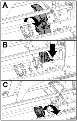
Hold the lower section of the rocker switch (Figure 9) until the following 3 things happen (Figure 10):
-
The cam assembly rotates toward the operator station.
-
The elevator lowers.
-
The loader arms rotate to the drill pipe.
-
-
Release the rocker switch to proceed to the next step in the sequence (Figure 11).

-
Break the pipe connection; refer to Removing Drill Pipes in the Operator’s Manual.
-
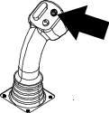
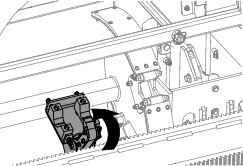
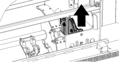
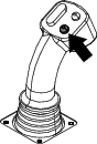
Hold the upper button on the joystick to grip the pipe (Figure 12 and Figure 13) and release the button.
-
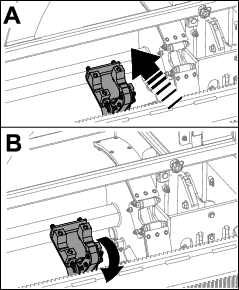
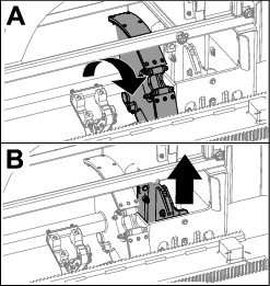
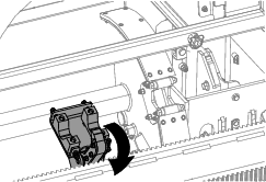
Hold the lower section of the rocker switch (Figure 15) until the arms rotate with the pipe back to the home position and the grippers open as the pipe enters the cam assembly pocket (Figure 16).

-
Release the rocker switch to proceed to the next step in the sequence (Figure 17).

-
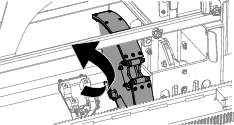
Hold the lower section of the rocker switch (Figure 18) until the cam assembly rotates to the selected row under the pipe box (Figure 19).
-
Release the rocker switch to proceed to the next step in the sequence (Figure 20).
-
Hold the lower section of the rocker switch (Figure 21) until the elevator puts the pipe back in the pipe box and the cam rotates to the home position (Figure 22).
-
Release the rocker switch to start the pull-pipe process again.
Pushing Pipe in SmartTouch Mode
Start the SmartTouch mode with the cam assembly in the home position (row 4 of the pipe box).
Important: Ensure that you hold the lower section of the cam rocker switch, on the left joystick, completely down until the action is complete in each step (Figure 23).
Hold the upper section of the cam rocker switch, on the left joystick, completely down until all actions are complete to go to the previous step in the sequence (Figure 24).
-
Push button 1 to select push pipe (Figure 25).
-
Push buttons 2 and 3 to select the row where you want to get the pipe (Figure 25).

-
Hold the lower section of the rocker switch (Figure 27) until the cam assembly rotates to the selected row and the elevator lowers the pipe into the opening (Figure 28).
-
Release the rocker switch to proceed to the next step in the sequence (Figure 29).

-
Hold the lower section of the rocker switch (Figure 30) until the cam assembly fully rotates forward to the rack and the elevators lift the remaining pipe into the pipe box (Figure 31).
-
Release the rocker switch to proceed to the next step in the sequence (Figure 32).

-
Hold the lower section of the rocker switch (Figure 33) until the loader arms rotate toward the pipe box. As they rotate past the cam assembly the pipe grippers close on the pipe, bringing it to the drill string (Figure 34).
-
Release the rocker switch to proceed to the next step in the sequence (Figure 35).
-
Make the pipe connection; refer to Adding Drill Pipes in the Operator’s Manual.
-
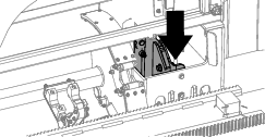
Hold the lower button on the joystick (Figure 36) to release the pipe (Figure 37) and release the button.
-
Hold the lower section of the rocker switch (Figure 39) until the loader arms rotate back and the cam assembly returns to the home position (row 4) (Figure 40).
-
Release the rocker switch to start the push-pipe process again. The cam assembly goes to the row picked in step 2 of Pulling Pipe in SmartTouch Mode.
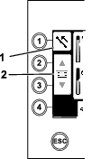
Hours Screen Options
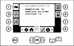
Machine Hours Screen
To access this screen, push button 1 on the Hours screen.
This screen shows the operating hours of the machine. You cannot change Machine 1 but you can reset Machine 2.
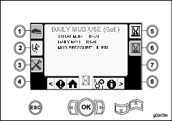
Mud Use Screen
To access this screen, push button 2 on the Hours screen.
This screen shows the mud volume used.
To switch between gallons and liters, refer to Figure 51, Language and Units Options Screen.
You cannot change the total mud, but you can reset the daily mud using button 8.
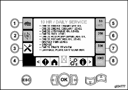
Lubrication and Maintenance Screens
To access this screen, push button 3 on the Hours screen.
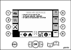
These screens provide the user with the daily maintenance schedules in the increments listed below.
To reset the maintenance interval, navigate to the Parameters Options Screen, push the down arrow to scroll to the maintenance options screen, and enter pin number 12356.
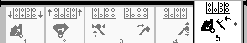
Push the following buttons to attain the subsequent maintenance schedule:
-
Button 3—10-hour/Daily (Figure 43)
-
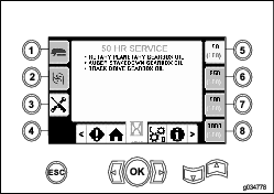
Button 5—50-hour (Figure 44)
-
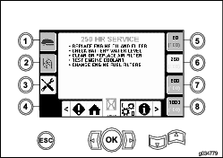
Button 6—250-hour (Figure 45)
-
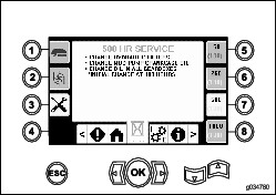
Button 7—500-hour (Figure 46)
-
Button 8—1,000-hour (Figure 47)
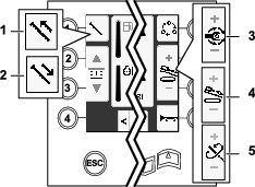
Settings Screen Options
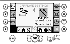
Carriage Settings Screen
Push button 1 on the Settings screen.
Use this screen to change the carriage settings. Use the up and down arrows to rotate between push pipe, pull pipe, and neutral.
Push the OK button to turn SmartTouch™ on and off.
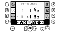
Control Mode Screen
Push button 2 on the Settings screen.
Use this screen to select between the 2 joystick control options. Push the up and down arrows to to switch between Mode I and Mode II.
-
Mode I—The right joystick controls the thrust and the rotation functions. The left joystick controls the wrench and pipe loader functions.
-
Mode II—The right joystick controls the thrust and the pipe loader elevator function. The left joystick controls the rotation, wrench, and pipe loader functions.
Parameters Options Screen
Push button 3 on the Settings screen.
The pin number to change the parameters is 73236531.
Push the down arrow to scroll to the maintenance options screen to reset the maintenance interval. Enter pin number 12356.
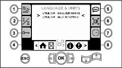
Language and Units Options Screen
Push button 5 on the Settings screen to access the language and units Screen. Push the up and down arrows to switch between English units and metric units.
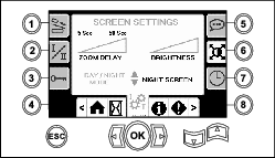
Screen Settings
Push button 6 on the Settings screen to switch between zoom delay, brightness, and day or night mode. Use the up and down arrows to adjust the parameters.
The Main Drilling Screen zooms into the drilling functions. These settings adjust the delay on how long it takes to zoom.
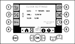
Clock Settings Screen
Push button 7 on the Settings screen to switch between the clock options. Use the up and down arrows to adjust the parameters.
Once you are on this screen, push button 7 to rotate between date, time, and 12/24.
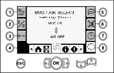
Mud or Air Hammer Selection Screen
Push button 8 on the Settings screen to access this screen. Use the up and down arrows to switch been mud and air hammer.
This updates the display on the home screen (Figure 1).
I/O Screens
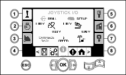
Joystick I/O Screen
Push button 1 on the I/O screen to rotate between the Drill and Setup options. The icon turns green when the associated function is actuated.
When the rocker switch on the left control panel is in the Drill position, the upper left icon turns green and the joystick voltages can be checked as well as verify the 2-Speed, and Exit Side Lockout inputs.
When the rocker switch is in the Setup position, the upper right icon is green. The setup position allows you to move the machine and prepare for drilling.
-
The rotary voltage ranges from 0.0 to 8.5 V and can be present for either make (upper icon) or break (lower icon) as the selected rotary joystick is moved.
-
The carriage indicates a voltage range from 0.0 to 10.0 V in the joystick selected direction for thrust or pullback.
-
The lower left icon indicates the carriage position of wrench, load, or carriage back as the carriage moves to the most rearward positions.
-
The lower center icon indicates if the 2-speed selection of the carriage speed has been selected.
-
The lower right icon indicates the status of the Exit Side Lockout (ESL). If the indicator is black, the carriage and rotary actions are inhibited.
Engine I/O Screen
To access this screen push button 2 on the I/O screen.
This screen displays engine information.
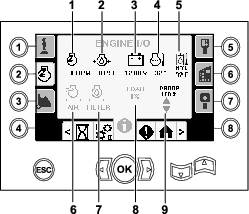
Engine speed (rpm) icon: displays, in steps of 100, the engine speed (rpm).
Engine-oil pressure icon: displays the engine-oil pressure (bar or psi).
Battery voltage icon: displays the battery voltage.
-
If the engine is shut off, the voltage is measured by the Toro controller.
-
If the engine is running, the voltage is supplied by engine controller.
Engine temperature icon: displays the engine coolant temperature measured at the reservior. The temperature drops to 40°F when the engine is shut off.
Air filter icon: the air filter icon is green unless the filter is plugged then the indicator is red.
Hydraulic-fluid filter icon: the hydraulic-fluid filter icon is green unless the filter is plugged then the indicator is red.
Engine load icon: displays the percent of the engine load.
Engine droop icon: select the allowable engine droop of 80, 90, or 100%. The droop value is the lowest point below low-load speed (rpm) (under 75 percent load) that the engine may decrease before the drive to the rotary head is decreased to maintain the lowest value. Push the up and down arrows to select the droop value.
Cam Arm I/O Screen
To access this screen push button 3 on the I/O screen.
Use this screen to adjust the cam and pipe loader calibration options.
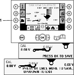
The 2 voltages on the bottom indicate the loader arm and cam actual voltage from the sensors. The voltages range from 1.0 to 4.0 V. Any voltage higher or lower indicates either sensor failure or incorrect calibration.
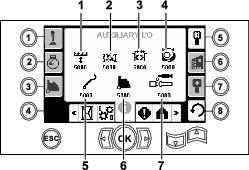
Auxiliary I/O Screen
To access this screen push button 5 on the I/O screen.
All icons change from black to green when you operate the associated functions.
Controller I/O Screen
To access this screen push button 6 on the I/O screen.
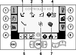
Seat switch icon: shows an arrow out when the operator seat is empty; the switch shows a figure icon when you are in the operator seat.
-
Shows the seat with an error when the operator seat is unoccupied
-
Shows the seat with a figurine when the operator seat is occupied
Exit side lockout icon: changes from black to green when in operation.
Pedestrian gate icon:
-
Shown in the UP position with a figurine: the gate is not in the correct position for drilling
-
Shown in the DOWN position: the gate is correctly positioned for drilling
Cam override input icon: turns green when the override button is pushed on the joystick.
Mud pump status icon:
-
Black: mud pump is off
-
Yellow: mud pump is in standby
-
Green: mud pump is in on
-
Green with 100: mud pump is in max flow
Mud pump flow icon: indicates the input from the rocker switch on the joystick.
-
When the rocker switch is actuated up, the indicator turns green with a blue up/increase arrow.
-
When the rocker switch is actuated down, the indicator turns green with a blue down/decrease arrow.
-
The icon is black when the rocker switch is not pressed.
Processor indicator icon: shows a red X to indicate a problem with the expansion processor located next to the main controller.
Travel Pendant I/O Screen
To access this screen push button 7 on the I/O screen.
The travel pendant screen shows the voltage and position of the joystick located on the pendant.
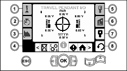
The red dot appears in the center of the target and the FNR (forward, neutral, reverse) and Steer voltage shows 2.5 V prior to allowing the drill to move. If the red dot travels outside of the outermost black ring, service or replace the pendant with a new pendant. The indicators to the right and left of the circle show the direction of the track travel. The voltages show a range from 0 to 10.0 V.
Errors and Machine Information Screens
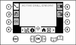
Drill Errors Screens
To access this screen push button 1 on the Errors and Machine Information screen.
This screen displays any drill errors.
Use the up and down arrows to scroll through the errors. Contact your Authorized Service Dealer for codes that cannot be cleared.
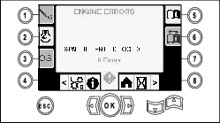
Engine Errors Screen
To access this screen push button 2 on the Errors and Machine Information screen.
This screen displays any engine errors.
Use the up and down arrows to scroll through the errors. Contact your Authorized Service Dealer for codes that cannot be cleared.
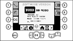
Machine Information Screen
To access this screen push button 3 on the Errors and Machine Information screen.
This screen displays the machine information including the model, serial number, and software version.
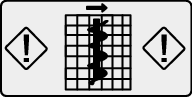
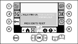
Carriage Crash Warning Icon
The carriage crash warning screen (Figure 64) appears if the following occurs:
-
The carriage is in the drill area and you try to operate the loader arm or pipe cam or
-
You try to operate the carriage when the loader arm or pipe cam is not in the home position.
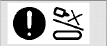
To clear this warning, do the following:
-
Move the cam assembly to the home position and/or
-
Reverse the carriage
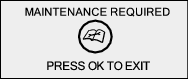
Maintenance Required Icon
This icon (Figure 65) displays when maintenance is required.
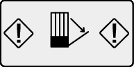
Pedestrian Gate Warning Icon
This icon (Figure 66) displays if the pedestrian gate is not in the lowered position.
Stake Down Cage Warning Icon (CE models only)
This icon (Figure 67) displays if the stake down cage door is not closed.