
Maintenance
-
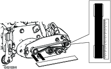
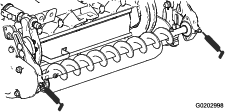
Ensure that the brush is parallel to the roller with 1.50 mm (0.06 inch) clearance to light contact.
-
Grease fittings every 50 hours or after every washing.
-
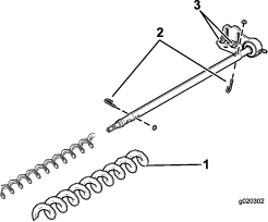
When replacing roller brush, torque J-bolts to 2 to 3 N⋅m (20 to 25 in-lb).
-
When replacing the brush shaft driven pulley, torque the nut to 36 to 45 N⋅m (27 to 33 ft-lb).
-
When replacing the brush drive pulley, torque the bolt to 47 to 54 N⋅m (35 to 40 ft-lb).
Important: Backlapping at the incorrect reel speed may loosen and strip the drive pulley threads. Refer to the Cutting Unit Operator’s Manual for backlapping procedure.
-
Roller brush, idler bearing, and belt are considered consumable items.
Checking and Adjusting the Pulley Alignment
-
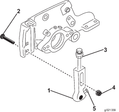
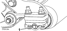
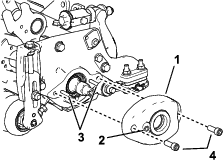
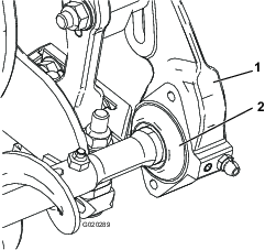
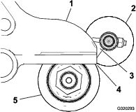
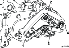
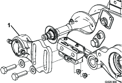
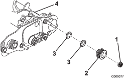
The driven pulley (at roller brush shaft) can move in or out (Figure 33).
Note: Make note of which way the pulley needs to move.
-
While rotating the reel, which will rotate the drive pulley, pry the belt off the drive pulley (Figure 33
Note: Wear a padded glove or use a heavy rag to rotate the reel.
-
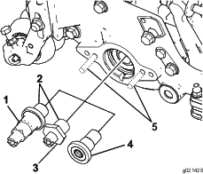
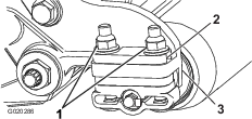
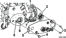
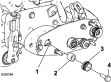
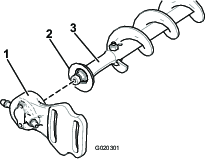
Remove the lock nut securing the driven pulley to the brush shaft (Figure 33 or Figure 34).
Note: Put a 1/2 inch wrench on the roller brush shaft flats to keep it from rotating.
-
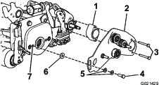
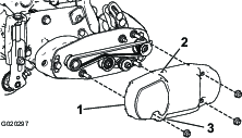
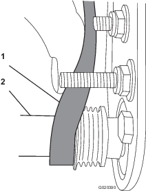
Remove the driven pulley from the shaft (Figure 34).
Note: If the pulley needs to move out, add one 0.8 mm (0.032 inch) thick spacer (Figure 34). If the pulley needs to move in, remove the existing 0.8 mm (0.032 inch) thick spacer.
-
Install the pulley.
-
While holding the roller brush shaft flats, secure the pulley on the shaft with the 3/8–16 flange nut previously removed.
Note: Seat the locknut then torque it to 36 to 45 N⋅m (27 to 33 ft-lb).
-
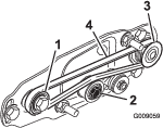
Install the belt onto the pulleys as follows:
-
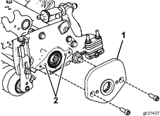
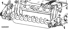
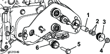
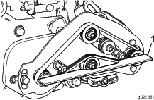
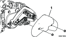
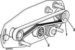
Loop the belt around the drive pulley and then over the top of the idler pulley (Figure 21).
-
Start the belt on the driven pulley (Figure 21).
-
Use a 9/16 inch deep-well socket to rotate the brush assembly and guide the belt onto the driven pulley (Figure 36).
Important: Make sure the ribs on the belt are properly seated in the grooves in each pulley. Also, make sure the belt is in the center of the idler pulley.
-
-
Check the pulley alignment again; repeat this procedure if necessary.
Restraining the Reel
Warning
The cutting reel blades are sharp and capable of amputating hands and feet.
-
Keep your hands and feet outside of the reel.
-
Ensure that the reel is restrained before servicing it.
Restraining the Reel for Removing Threaded Inserts
-
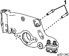
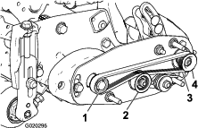
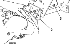
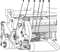
Loosen the shield-bolt on the left side of the cutting unit and raise the rear shield (Figure 37).
-
Insert a long-handled pry bar (recommended 3/8" x 12" with screwdriver handle) through the back of the cutting reel, closest to the side of the cutting unit that you will be torquing (Figure 37).
-
Place the pry bar against the weld side of the reel support plate (Figure 37).
Note: Insert the pry bar between the top of the reel shaft and the backs of 2 reel blades so that the reel will not move.
Important: Do not contact the cutting edge of any blades with the pry bar; this may damage the cutting edge and/or cause a high blade.
Important: The insert on the left side of the cutting unit has left-hand threads. The insert on the right side of the cutting unit has right-hand threads.
-
Rest the handle of the pry bar against the rear roller.
-
Complete the removal of the threaded insert while ensuring that the pry bar stays in place, then remove the pry bar.
-
Lower the rear shield and tighten the shield-bolt.
Restraining the Reel for Installing Threaded Inserts
-
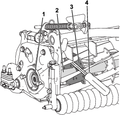
Insert a long-handled pry bar (recommended 3/8" x 12" with screwdriver handle) through the front of the cutting reel, closest to the side of the cutting unit that you will be torquing (Figure 38).
-
Place the pry bar against the weld side of the internal cutting reel reinforcement (Figure 38).
Note: The pry bar should contact a blade at the front, the reel shaft, and a blade at the back of the back of the reel, locking it in place.
Important: Do not contact the cutting edge of any blades with the pry bar; this may damage the cutting edge and/or cause a high blade.
Important: The insert on the left side of the cutting unit has left-hand threads. The insert on the right side of the cutting unit has right-hand threads.
-
Rest the handle of the pry bar against the roller
-
Per the insert’s installation instructions and torque requirements, complete the installation of the threaded insert while ensuring that the pry bar stays in place, then remove the pry bar.