Note: Determine the left and right sides of the cutting unit from
behind the cutting unit.
Important: The Rear Roller Brush Kit is only to be used when cutting in
the height of cut range of 6 to 25 mm (1/4 to 1 inch).
Install the high height-of-cut brush when cutting above 25 mm
(1 inch) height of cut (7 maximum spacers installed below the side
plate pad).:
-
Part 110-1740 for 22-inch cutting units
-
Part 115-0838 for 27-inch cutting units
-
Part 115-0849 for 32-inch cutting units
Install the HD brush for heavy-duty conditions (worm castings,
clay, etc.).:
Refer to Installing the High Height-of-Cut Brush or HD Brush (Optional).
Rear Roller Brush Kit Model 137-5991 may be used on
the following:
Reelmaster 5210 and 5410 Cutting Unit Models 03661, 03694, and
03695
Rear Roller Brush Kit Model 137-5992 may be used on
the following:
-
Reelmaster 5510 and 5610 Cutting Unit Models 03681,
03682, 03693, 03696 and 03697
-
Reelmaster 6500 and 6700 Cutting Unit Models 03863,
03864, 03698 and 03699
Rear Roller Brush Kit Model 137-5993 may be used on
the following:
-
Reelmaster 3100 Cutting Unit Models 03180, 03181,
and 03183 with the 27-inch Lift Arm Kit, Model 03172
-
Reelmaster 7000 Cutting Unit Models 03710 and 03711
Rear Roller Brush Kit Model 137-5994 may be used on
the following:
-
Reelmaster 3100 Cutting Unit Model 03182 with the
32-inch Lift Arm Kit, Model 03173
-
Reelmaster 7000 Cutting Unit Model 03712
Note: If you are installing a groomer kit and a brush kit on the cutting
unit, install the groomer kit first.
Gathering the Appropriate Tools
Acquire the following tools before proceeding with the installation:
-
1/2 deep-well socket
-
9/16 socket
-
5/8 socket
-
1/2 wrench
-
9/16 wrench
-
1/8 Allen wrench
-
5/16 Allen wrench
-
3/8-16 tap
-
12-inch straight edge (optional, Toro Part 114-5446)
-
Torque wrench (foot-pound)
-
Torque wrench (inch-pound)
-
Blue 243 Loctite
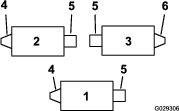
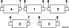
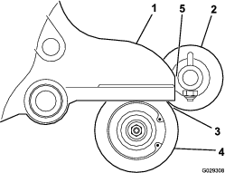
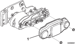
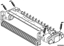
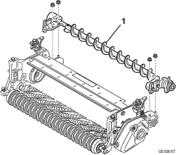
Determining the Orientation of the Roller Brushes
All cutting units are shipped with the counterweight mounted
to the left end of the cutting unit. Use the Figure 1 to determine the position
of the roller brushes and reel motors for Reelmaster 3100-D or Figure 2 for Reelmaster
5210, 5410, 5510, 5610, 6500-D, 6700-D, and 7000-D.
Note: These instructions and illustrations show the installation of
the kit on cutting units with the end weights mounted on the left
end of the cutting unit.
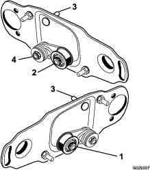
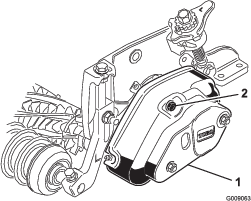
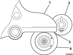
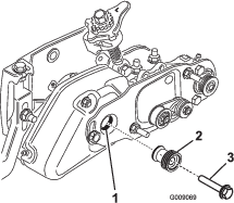
Adjusting the Position of the Idler Pulley Assembly
On the left front and left rear cutting units, reverse the idler
pulley assembly to mount on the right end of
the cutting unit (Figure 3), as follows:
-
Remove the idler pulley assembly from the left end
of the cutting unit and mount it to the lower hole in the brush plate
on the right end of the cutting unit (Figure 3).
Note: The idler pulley must pivot freely; do not overtighten the locknut
on the idler pivot bolt.
-
Remove the carriage bolt and nut and relocate them
to the upper hole previously occupied by the idler pulley assembly
(Figure 3).
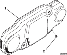
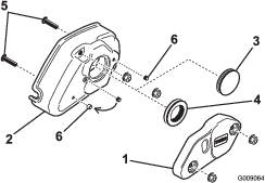
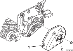
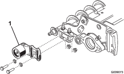
Removing the Brush Cover Drain Plug
Remove only the bottom drain plug (Figure 4) from the brush covers. This
allows moisture to drain from the belt area.
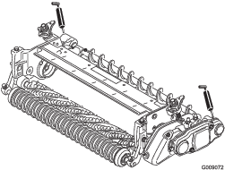
Installing the Roller Brush
Parts needed for this procedure:
| Roller-brush housing | 1 |
| Allen-head bolt, 3/8 x 1 inch | 2 |
| Roller-brush assembly | 1 |
| Shoulder bolt | 1 |
| Belt cover/plate assembly | 1 |
| Bolt, 5/16 x 5/8 inch | 2 |
| Spacer | 1 |
| Drive pulley | 1 |
| Flange-head bolt, 3/8 x 2 inches | 1 |
| Belt | 1 |
| Shim washer (as required) | 1 |
Installing the Brush on Cutting Units not Equipped with Groomers
-
Park the traction unit on a level surface and engage
the parking brake.
-
Ensure that the cutting units are disengaged. Shut
off the engine off and remove the key. Remove all cutting units from
the traction unit.
Important: Check the cutting unit for the desired height of cut and attitude.
Reset it according to the Operator’s Manual, if required, before installing the Rear Roller Brush Kit.
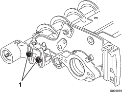
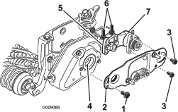
-
Remove the 2 bolts securing the counterweight to the
left end of the cutting unit. Remove the counterweight (Figure 5).
-
Using a 3/8-16 tap, remove the paint in the outer
mounting holes in the side-plate (Figure 5).
-
Mount the roller-brush housing to the reel-bearing
housing with 2 Allen-head bolts (3/8 x 1 inch) (Figure 6). Position the roller-brush
housing so that the threaded hole is toward the front of the cutting
unit.
Note: Make sure that the O-ring is properly positioned in the roller-brush
housing.
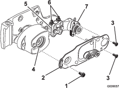
-
Remove the 2 flange locknuts securing each roller
bracket to the side-plates (Figure 7). Do not remove the bolts. Also, remove any 6 mm (1/4 inch) spacers from the top side of the
side-plate mounting flange.
-
Position the roller-brush mounting brackets onto the
roller-bracket bolts (Figure 8).
Important: The roller-brush mounting brackets must be mounted directly
to the top surface of the cutting-unit side-plate mounting flange. Do not put spacers between the roller-brush mounting brackets and
the side-plate mounting flanges. Install additional 6 mm
(1/4 inch) spacers on the top side of the roller-brush mounting bracket
(Figure 9).
-
Secure the roller-brush mounting brackets to the cutting-unit
side plates with the nuts previously removed.
-
Slide each excluder seal outward until the lip seals
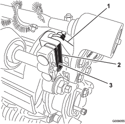
are in light contact with each bearing housing (Figure 10).
-
Apply a coating of grease to the inner diameter of
the grommet in the bearing housing (Figure 11).
-
Loosen, but do not remove, the bolts securing the
roller-brush-bearing housing to the roller-brush mounting bracket
(Figure 11).
-
Install the roller-brush pivot plate (Figure 11).
Note: When you insert the protrusion on the pivot plate into the grommet
in the bearing housing, ensure that the grommet stays properly seated
in the housing.
Note: The roller-brush pivot plate is properly seated when there is
no resistance from the rubber grommet and it pivots freely.
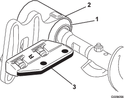
-
Apply 243 Loctite (blue) to the 2 bolts (5/16 x 5/8
inch) and use them to mount the brush plate to the roller-brush-bearing
housing (Figure 11).
Note: Torque the bolts to 20 to 25 N∙m (15 to 19 ft-lb).
-
Check to make sure that the roller-brush plate is
parallel to the cutting-unit side plate. If it is not parallel, proceed
as follows:
-
Loosen the 2 flange locknuts securing the roller-brush
mounting bracket to the cutting unit side plate (Figure 11).
-
Rotate the roller-brush-bearing housing until the
brush plate is parallel to the cutting-unit side plate (Figure 11).
-
Tighten the 2 flange locknuts securing the roller-brush
mounting bracket to the cutting-unit side plate (Figure 11).
-
Loosen the 2 bolts securing each roller-brush-bearing
housing to the roller-brush mounting bracket (Figure 12 and Figure 13).
-
Position the roller brush so that it just touches
the rear roller (Figure 14).
Important: The roller-brush shaft must not contact the cutting-unit side-plate.
Important: Heavy brush contact on the roller causes premature brush wear.
Note: The roller brush shaft must be parallel to the rear roller.
Note: The orientation of the non-drive roller-brush-bearing housing
should be the same as drive-side bearing housing.
-
Tighten the 2 bolts securing each roller-brush-bearing
housing to the roller-brush mounting brackets.
-
Apply 243 Loctite (blue) to the shoulder bolt (Figure 11). Secure
the brush plate to the roller-brush housing with the shoulder bolt.
(Figure 11).
Note: Torque the bolt to 20 to 25 N∙m (15 to 19 ft-lb).
Note: The shoulder bolt should not clamp the plate to the housing.
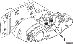
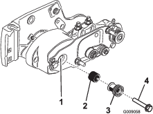
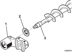
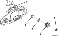
-
Install the spacer onto the shaft in the bearing housing
(Figure 15).
-
Insert the drive pulley into the spacer and onto the
driveshaft (Figure 15). Make sure that the pulley tabs are positioned in
the slot in the drive shaft.
-
Secure the pulley and spacer to the driveshaft with
a flange-head bolt (3/8 x 2 inch) (Figure 15).
Note: Torque the bolt to 47 to 54 N∙m (35 to 40 ft-lb).
Important: If the bolt is not properly torqued, the bolt will come loose.Restrain the reel for installation; refer to Restraining the Reel for Installing Threaded Inserts.
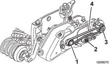
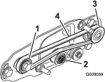
-
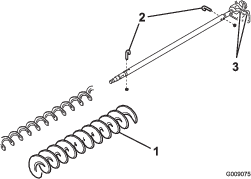
Install the belt onto the pulleys as follows:
-
Loop the belt around the driven pulley and then over the top of the idler pulley (Figure 16).
-
Start the belt on the drive pulley
(Figure 16).
-
While guiding the belt onto the drive pulley, rotate the reel forward to draw the belt onto the drive
pulley.
Note: Wear a padded glove or use a heavy rag to rotate the reel.
Important: Make sure that the ribs on the belt are properly seated in the
grooves in each pulley. Also, make sure that the belt is in the center
of the idler pulley.
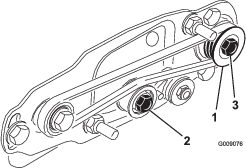
-
Push down on the idler pulley to ensure that the idler
pulley assembly pivots freely.
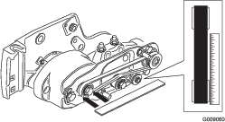
-
Check the alignment of the belt/pulleys as follows:
-
The belt must be properly tensioned (installed) prior
to checking alignment.
-
Lay a straightedge along the outer face of the drive pulley (Figure 17). Do not lay the straightedge across both the drive and driven pulleys.
-
The outer faces of the drive and driven pulleys should
be in line within 0.76 mm (0.030 inch).
-
If the pulleys are not aligned, Refer to Aligning the Pulleys.
-
If the pulleys are aligned, continue with the installation.
-
Do not use the idler pulley to
check alignment.
Important: The belt may fail prematurely if the pulleys are not properly
aligned.
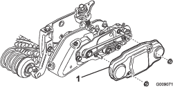
-
Slide the belt cover onto the mounting bolts and secure
with 2 flange nuts (Figure 18).
Important: Do not overtighten the flange nuts, as damage to the cover may
occur.
-
Lubricate the grease fittings on each of the roller-brush-bearing
housings and on the remainder of the cutting unit with No. 2 lithium
grease (Figure 19).
Note: Wipe off any excess grease, specifically around the excluder
seals.
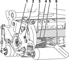
Installing the Brush on Cutting Units Equipped with Groomers
Note: If a groomer kit and a brush kit are going to be installed on
the cutting unit, install the groomer kit first.
-
Remove the 2 groomer cover mounting nuts and remove
the cover (Figure 20).
-
Remove the 2 flange nuts (5/16 inch) securing the
groomer weight to the groomer cover and remove the weight (Figure 21).
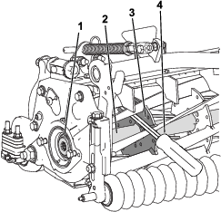
-
Remove the solid grommet from the cover and replace
it with the rubber grommet ring included with the groomer (Figure 21).
-
Remove the 2 screws (5/16 x 1-1/4 inch) threaded into
the cover (Figure 21).
-
Remove the setscrew from the center hole in the groomer
cover (Figure 21).
-
Install the previously removed setscrew and the setscrew
included with the Groomer Kit, into the holes previously used for
the cover mounting screws. Apply 243 Loctite (blue) to the setscrews
prior to installation.
Note: The setscrews should be flush with the groomer cover.
-
Install the groomer cover and secure it with 2 flange
nuts (5/16 inch) (Figure 22).
Important: Do not overtighten the nuts.
-
Apply grease to the inside diameter of the grommet
in the groomer cover (Figure 22).
-
Remove the 2 nuts securing each roller bracket to
the side plates (Figure 23). Do not remove the bolts.
Note: Remove any 6 mm (1/4 inch) spacers positioned on the top side
of the side plate mounting flange.
-
Position the roller brush assembly mounting brackets
onto the roller bracket bolts (Figure 24). Secure the brush assembly
mounting brackets to the cutting unit side plates with the nuts previously
removed.
Important: The roller brush assembly mounting brackets must be mounted
directly to the top surface of the cutting unit side plate mounting
flange. Do not put spacers on the roller brush mounting brackets and
the side plate mounting flanges. Install additional 6 mm (1/4 inch)
spacers on the top side of the roller brush mounting bracket (Figure 25).
-
Slide each excluder seal outward until the lip seals
are in light contact with each bearing housing (Figure 26).
-
Loosen but do not remove the bolts securing the roller
brush bearing housing to the roller brush mounting bracket (Figure 27).
-
Install the roller brush pivot plate (Figure 27). Ensure
that the grommet stays properly seated on the cover when the protrusion
on the pivot plate is inserted into the grommet on the groomer cover.
Note: The roller brush pivot plate is properly seated when there is
no resistance from the rubber grommet and it pivots freely.
-
Apply 243 Loctite (blue) to the 2 bolts (5/16 x 5/8
inch) and use them to mount the brush plate to the roller brush bearing
housing (Figure 27). Torque the bolts to 20 to 25 N∙m (15 to 19 ft-lb).
-
Check to make sure that the roller brush plate is
parallel to the cutting unit side plate. If it is not parallel, do
the following:
-
Loosen the 2 flange locknuts securing the roller brush
mounting bracket to the cutting unit side plate (Figure 27).
-
Rotate the roller brush bearing housing until the
brush plate is parallel to the cutting unit side plate (Figure 27).
-
Tighten the 2 flange locknuts securing the roller
brush mounting bracket to the cutting unit side plate (Figure 27).
-
Loosen the 2 bolts securing each roller brush bearing
housing to the roller brush mounting bracket (Figure 12 and Figure 13).
-
Position the roller brush so it is in light contact
with (i.e., just touching or resting on) the rear roller (Figure 14).
Important: The roller brush shaft must not contact the cutting unit side
plate.
Important: Heavy brush contact on the roller will cause premature brush
wear.
Note: The roller brush shaft must be parallel to the rear roller.
Note: The orientation of the non–drive roller brush bearing
housing should be the same as drive side bearing housing.
-
Tighten the 2 bolts securing each roller brush bearing
housing to the roller brush mounting brackets.
-
Apply 243 Loctite (blue) to the shoulder bolt (Figure 27). Secure
the brush plate to the groomer cover with the shoulder bolt. (Figure 27). Torque
the bolt to 20 to 25 N∙m (15 to 19 ft-lb).
Note: The shoulder bolt should not clamp the plate to the housing.
-
Remove the bolt securing the groomer pulley to the
drive shaft (Figure 31).
-
Insert the brush drive pulley into the groomer drive
pulley and onto the drive shaft (Figure 31). Make sure that the pulley
tabs are positioned in the slot in the drive shaft.
-
Secure the drive pulley to the shaft with a flange-head
bolt (3/8 x 2 inch) (Figure 31). Torque the bolt to 47 to 54 N∙m (35 to
40 ft-lb).
Important: If the bolt is not properly torqued, the bolt will come loose.Restrain the reel for installation; refer to Restraining the Reel for Installing Threaded Inserts.
-
Install the belt onto the pulleys as follows:
-
Loop the belt around the driven pulley and then over the top of the idler pulley (Figure 32).
-
Start the belt on the drive pulley
(Figure 32).
-
While guiding the belt onto the drive pulley, rotate the reel forward to draw the belt onto the drive
pulley.
Note: Wear a padded glove or use a heavy rag to rotate the reel.
Important: Make sure that the ribs on the belt are properly seated in the
grooves in each pulley. Also, make sure the belt is in the center
of the idler pulley.
-
Push down on the idler pulley to ensure that the idler
pulley assembly pivots freely.
-
Check the alignment of the belt/pulleys as follows:
-
The belt must be properly tensioned (installed) prior
to checking alignment.
-
Lay a straight edge along the outer face of the drive pulley (Figure 33). Do not lay the straight edge across both the drive and driven pulleys.
-
The outer faces of the drive and driven pulleys should
be in line within 0.76 mm (0.030 inch).
-
If the pulleys are not aligned, Refer to the section
on Pulley Alignment.
-
If the pulleys are aligned, continue with the installation.
-
Do not use the idler pulley to
check alignment.
Note: The belt may fail prematurely if the pulleys are not properly
aligned.
-
Slide the belt cover onto the mounting bolts and secure
with 2 flange nuts (Figure 34).
Important: Do not overtighten nuts as damage to cover may occur.
-
Lubricate the grease fittings on each of the roller
brush bearing housings and on the remainder of the cutting unit with
No. 2 general-purpose, lithium-based grease (Figure 35).
Note: Wipe off any excess grease, specifically around the excluder
seals.
Installing the High Height-of-Cut Brush or HD Brush (Optional)
Parts needed for this procedure:
| High height of cut brush (optional) | – |
| HD brush (optional) | – |
Install the high height-of-cut brush when cutting from 2.5 to
5.1 cm (1 to 2 inches) height of cut (7 maximum spacers installed
below the side plate pad).:
-
Part 110-1740 for 22 inch cutting units
-
Part 115-0838 for 27 inch cutting units
-
Part 115-0849 for 32 inch cutting units
Install the HD brush for heavy-duty conditions (worm castings,
clay, etc.).:
-
If a roller brush is installed on the cutting unit,
remove the 2 bolts, washers and nuts securing the non-drive-bearing
housing to the bearing-housing mounting bracket (Figure 36 and Figure 37).
-
Slide the non-drive-bearing housing and the excluder
seal off the brush shaft (Figure 37).
-
Remove the 2 J-bolts and nuts (Figure 38).
-
Slide the existing brush off the brush shaft (Figure 38).
-
Loosen the 2 bolts, washers, and nuts securing the
drive-bearing housing to the bearing-housing mounting bracket (Figure 38).
-
Slide the high height-of-cut brush or HD brush onto
the brush shaft (Figure 38).
-
Clamp the brush onto the shaft with the 2 J-bolts
and nuts previously removed (Figure 38).
Important: Insert the threaded end of the J-bolts thru the outer holes
of the brush shaft while hooking the curved ends of the J-bolts into
the inner holes.
-
Torque the J-bolt locknuts to 2 to 3 N∙m (20 to 25
in-lb).
-
Install the excluder seal and the non-drive-bearing
housing onto the brush shaft (Figure 37).
-
Mount the non-drive-bearing housing to the bearing-housing
mounting bracket with the 2 bolts, washers, and nuts previously removed.
Note: Be careful not to knock the seal spring off.
-
Tighten the 2 bolts, washers, and nuts securing the
drive-bearing housing to the bearing-housing mounting bracket.