Safety
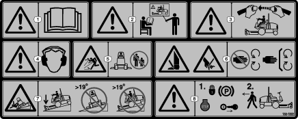
Safety and Instructional Decals
Installation
Preparing the Machine
-
Park the machine on a level surface.
-
Lower the cutting units.
-
Engage the parking brake.
-
Shut off the engine and remove the key.
Installing the Hood Latch
Parts needed for this procedure:
| Latch | 1 |
| Latch key | 1 |
| Latch bracket | 1 |
| Carriage bolt (5/16 x 3/4 inch) | 1 |
| Flange nut (5/16 inch) | 1 |
Use the key to lock and unlock the latch.
-
Unlatch and raise the hood.
-
Remove the existing rubber grommet in the left side of the hood.
-
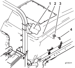
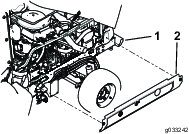
Remove the locking nut from the latch assembly (Figure 1).
-
Install the locking latch through the hole in the left side of the hood (Figure 1).
Note: Ensure the catch is positioned inside the hood and pointing downward.
-
Install the locking nut onto the latch to secure it to the hood.
-
Install the latch bracket to the frame with a carriage bolt (5/16 x 3/4 inch) and flange nut (5/16 inch) (Figure 2).
-
Close the hood slowly to see if latch catches.
-
If it does not, loosen the screws securing the latch bracket and adjust the bracket as necessary.
-
Tighten the bolt and verify that the latch catches.
-
Torque the nut and bolt to 40.7 to 49.7 N∙m (30 to 37 ft-lb).
Installing the Side-Panel Hardware
Parts needed for this procedure:
| Screw (5/16 x 3/4 inch) | 4 |
| Push nut (5/16 inch) | 4 |
| Hex nut (5/16 inch) | 1 |
-
Remove the existing hardware that secures the side panel to the machine and remove the side panel.
-
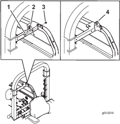
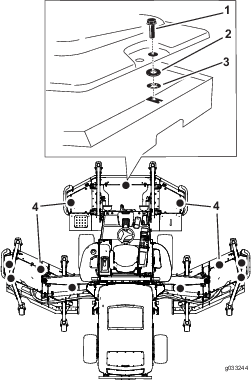
Install the 2 screws (5/16 x 3/4 inch) to the side panel and turn it over to install the 2 push nuts (5/16 inch) onto the screw (Figure 3).
-
Install the hex nut (5/16 inch) onto the screw to move the push nut tight against the side panel (Figure 3).
-
Remove the hex nut and move the remaining push nut tight against the side panel.
-
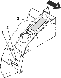
Install the side panel with the retained fastener to the machine (Figure 4).
Note: Do not tighten the screws more than 14 N∙m (120 in-lb).
-
Repeat this procedure for the opposite side.
-
Remove the hex nut when finished and discard.
Installing the Belt-Cover Hardware
Parts needed for this procedure:
| Thrust washer | 11 |
| Push nut (5/16 inch) | 11 |
-
Remove the bolt that secures the belt cover to the mower deck and remove the belt covers.
-
Install the existing bolt into the dedicated hole in the belt cover.
-
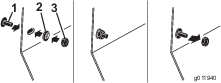
Install the thrust washer and push nut from underneath to the existing bolt to retain it to the belt cover as shown in Figure 5.
-
Install the belt cover to the mower deck. Use the retained bolt to secure it to the mower deck.
-
Repeat for all the belt cover hardware.
Adjusting the Machine Software
Contact your authorized Toro distributor to set the machine software to the CE Mode.
Installing the Decals
Parts needed for this procedure:
| CE warning decal (Part No. 132-1322) | 1 |
| CE mark decal | 1 |
Refer to Figure 6 for this procedure.
-
Install the CE warning decal (Part No. 132-1322) over the existing warning decal (Part No. 117-2754) on the storage center cover.
Note: The storage center is located to the left of the seat.
-
Install the CE mark decal next to the production year decal.