Installation
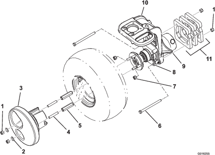
Parts needed for this procedure:
| Wheel weight | 1 |
| Weight plate | 3 |
| Locknut | 4 |
| Thrust washer | 2 |
| Stud | 2 |
| Wheel weight adapter | 2 |
| Hex-head screw | 2 |
Important: GR3300/3320 will comply with EN ISO 5395 and ANSI B71.4-2017 when this kit is installed in conjunction with the 3WD kit.
-
Park the machine on a level surface.
-
Shut off the engine, wait for all moving parts to stop, engage the parking brake, and remove the key.
-
Raise the machine with a jack at the jack point (Figure 1).
-
Remove the 4 lug nuts on the wheel in pairs positioned diagonally from each other (Figure 1).
-
Remove the tire and set it aside to be installed later.
-
Remove the 2 retaining bolts that secure the wheel motor to the castor fork (Figure 1).
-
Mount 3 weight plates to the right side of the castor fork with 2 hex-head bolts (1/2 x 6 inch) and 2 locknuts from the kit (Figure 1).
Note: Torque the locknuts to 65 to 85 ft-lb (88 to 115 N⋅m).
-
Position the weight onto the wheel rim of the removed tire to determine the location of the valve stems and the weight mounting fasteners.
Note: Mark the 2 holes on the wheel where the weight mounting fasteners will go.
-
Install the tire with 2 lug nuts previously removed in the other 2 (unmarked) holes.
-
Thread the 2 weight adapters from the kit onto the 2 remaining wheel studs (marked holes).
Note: Position the weight adapter so that the tapered end faces the wheel.
-
Torque the lug nuts and the weight adapters to 65 to 85 ft-lb (88 to 115 N⋅m).
-
Thread a stud into each of the 2 weight adapters all the way.
-
Install the wheel weight over the studs, weight adapters, and valve stem.
Important: Do not damage the valve stem.
-
Secure the wheel weight to the adapters with two washers and locknuts.
Note: Torque the locknuts to 65 to 85 ft-lb (88 to 115 N⋅m).
-
Lower the machine.
-
Torque the lug nuts, weight adapters, and locknuts to 65 to 85 ft-lb (88 to 115 N⋅m) every 200 operating hours.